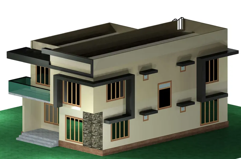
Project 2_Creating a 3D rendered model for a Residential Building in AutoCad
Project 2: Creating a 3D rendered model for a Residential Building in AutoCad
AIM
To create a 3D rendered model for a residential building in AutoCad.
INTRODUCTION
A rendering is a particular view of a 3D model that has been converted into a realistic image. It includes basic lighting such as Gouraud shading as well as more sophisticated effects that simulate shadows, reflection and refraction.
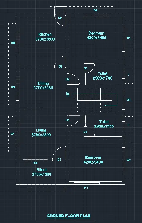
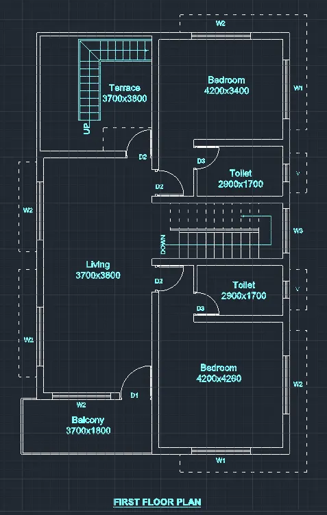
In this project, a plan for G+1 residential building is drawn. The ground floor of the residential building is designed with a living room, 2 bedrooms with attached toilets, a dining, a kitchen, a staircase and a sitout. The first floor of the residential building is designed with a living room, 2 bedrooms with attached bathrooms, a terrace, a staircase and a balcony. All dimensions are in millimeters 'mm' in this project. All the details regarding the bulding is given below.
First Floor details
Living Room: 3700mmx3800mm
Bedroom 1: 4200mmx3300mm
Bedroom 2: 4200mmx3400mm
Toilet 1: 2900mmx1700mm
Toilet 2: 2900mmx1700mm
Dining Room: 3700mmx3060mm
Kitchen: 3700mmx3800mm
Sitout: 3700mmx1800mm
Second Floor details
Living Room: 3700mmx8000mm
Bedroom 3: 4200mmx4260mm
Bedroom 4: 4200mmx3400mm
Toilet 3: 2900mmx1700mm
Toilet 4: 2900mmx1700mm
Balcony: 4400mmx1800mm
Terrace: 3815mmx3915mm
Wall Details
Exterior wall: 230mm
Interior wall: 115mm
Beam and Floor slab Details
Plinth beam: 300mmx450mm
Floor slab thickness: 150mm
Door Details
D1: 1100mmx2100mm
D2: 900mmx2100mm
D3: 800mmx2100mm
Window Details
W1: 2000mmx2000mm
W2: 2000mmx1600mm
W3: 1500mmx2100mm
W4: 2000mmx1200mm
V: 600mmx600mm
Staircase
Inside stair: 21 steps (Tread: 300mm, Riser: 150mm)
Ouside stairs: 3 steps (Tread: 300mm, Riser: 150mm)
Terrace stair: 17 steps (Tread: 250mm, Riser: 187.5mm)
PROCEDURE
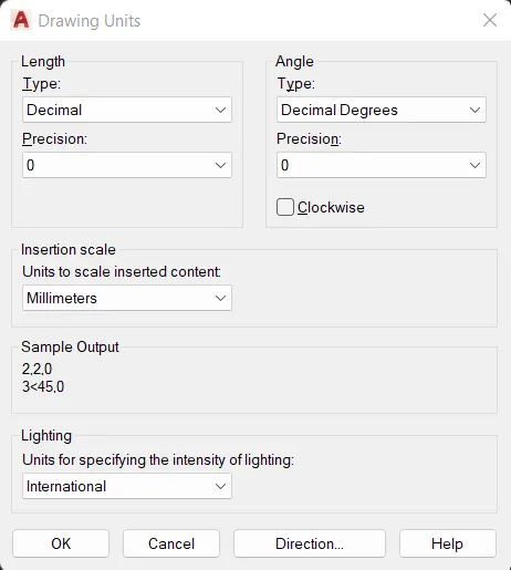
Open the AutoCAD Application and create a new AutoCAD file with imperial settings. Set the length type in 'Decimal' and precision (0), insertion scale to 'Millimeters' in the Drawing Units and press OK.
Layers are created, the different layers used in this project is shown below
1. Create plan for a residential building
- Type 'LA' in the command line and enter to get layers
- Create a new layer 'Plan'
- Draw walls, windows, doors, steps and projections using various commands. Following are the commands used to complete the ground floor plan and first floor plan
- XL (XLINE)
- OFFSET
- TR (TRIM)
- LINE
- C (CIRCLE)
- Type 'LA' in the command line and enter to get layers
- Create a new layer 'Texts'
- Using command 'MTEXT' multiline text is created to show the labels of the plan
- Ground Floor Plan
- First Floor Plan
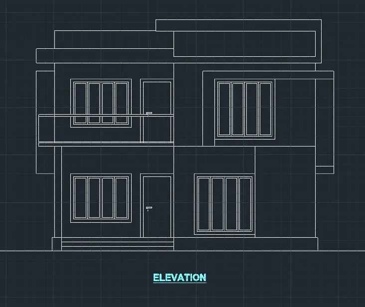
2. Create the elevation for the plan drawn
- Type 'LA' in the command line and enter to get layers
- Create a new layer 'Elevation'
- Draw walls, windows, doors, steps, projections and texts using various commands. Following are the commands used to complete the ground floor plan and first floor plan
- XL (XLINE)
- OFFSET
- TR (TRIM)
- LINE
- C (CIRCLE)
- Elevation
3. Create the 3D walls for ground floor
- Click on 'Workspace Switching' and select '3D Modelling'
- Type 'LA' in the command line and enter to get layers
- Create a new layer '3D Wall'
- Type 'CO' in the command line and enter to get copy tool
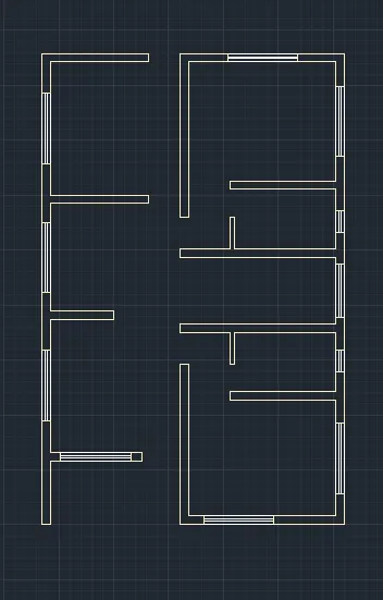
- Select the ground floor plan and paste it in some other place for extrution
- Type 'BO' in the command line and enter to get boundary creation tool
- Select 'Region' as Object type
- Pick all the wall regions
- Type 'EXT' in the command line and enter to get extrude tool
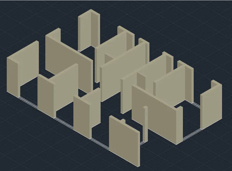
- Select the walls and extrude 3000mm in the z direction
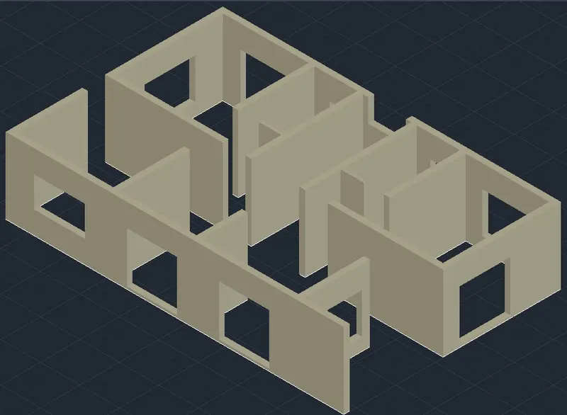
4. Create window openings
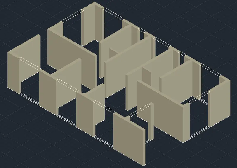
- Type 'REC' in the command line and enter to get rectangle
- Draw a rectangle on top and bottom of every windows in the plan
a) W1 (2000mmx2000mm)
- Type 'EXT' in the command line and enter to get extrude tool
- Select the bottom rectangle and extrude 100mm in the z direction
- Select the top rectangle and extrude 900mm in the -z direction
b) W2 (2000mmx1600mm)
- Type 'EXT' in the command line and enter to get extrude tool
- Select the bottom rectangle and extrude 500mm in the z direction
- Select the top rectangle and extrude 900mm in the -z direction
c) W3 (1500mmx2100mm)
- Type 'EXT' in the command line and enter to get extrude tool
- Select the bottom rectangle and extrude 2100mm in the z direction
d) W4 (2000mmx1200mm)
- Type 'EXT' in the command line and enter to get extrude tool
- Select the bottom rectangle and extrude 900mm in the z direction
- Select the top rectangle and extrude 900mm in the -z direction
e) V (600mmx600mm)
- Type 'EXT' in the command line and enter to get extrude tool
- Select the bottom rectangle and extrude 1500mm in the z direction
- Select the top rectangle and extrude 900mm in the -z direction
5. Create door openings
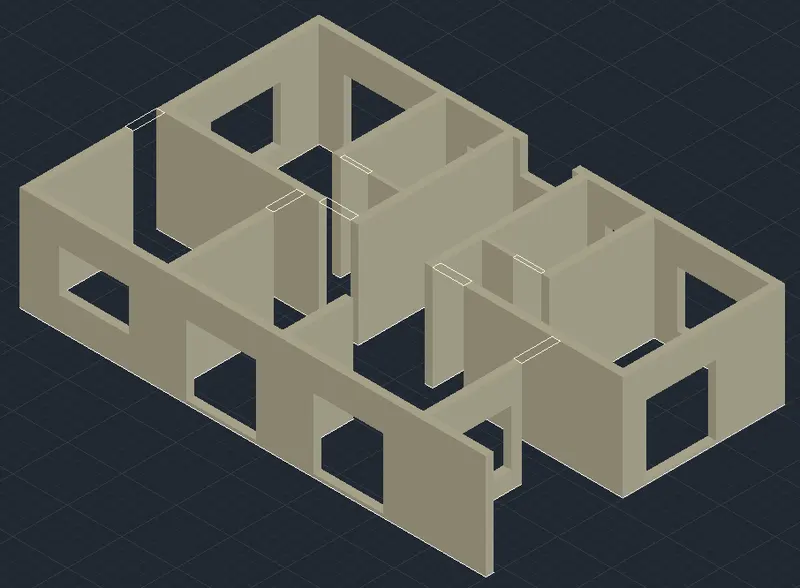
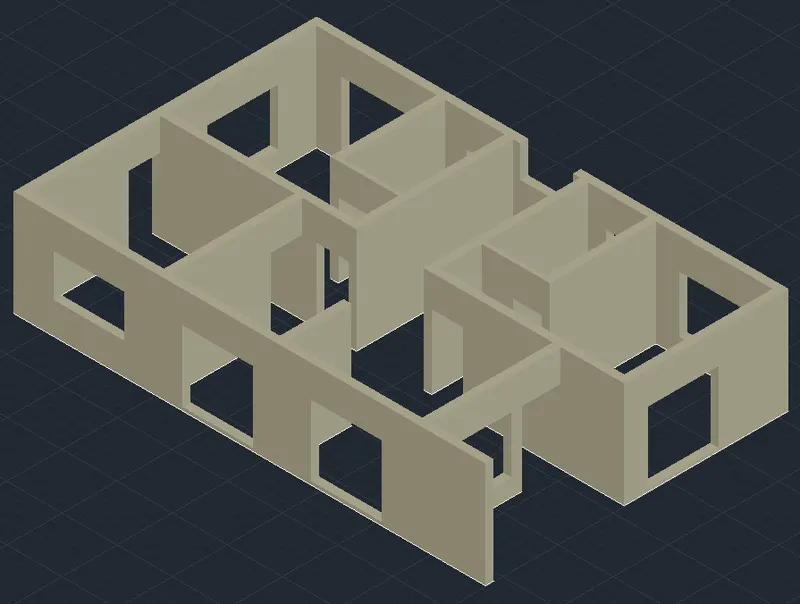
- Type 'REC' in the command line and enter to get rectangle
- Draw a rectangle on top of every doors in the plan
- Type 'EXT' in the command line and enter to get extrude tool
- Select the top rectangle and extrude 900mm in the -z direction
6. Create windows
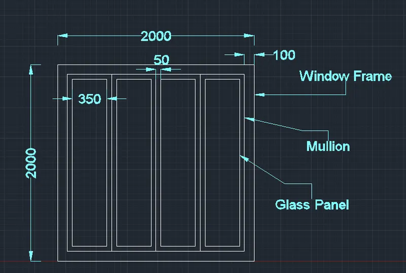
a) W1 (2000mmx2000mm)
- The window detail is given below
- Type 'LA' in the command line and enter to get layers
- Create a new layer '3D Window-Frame'
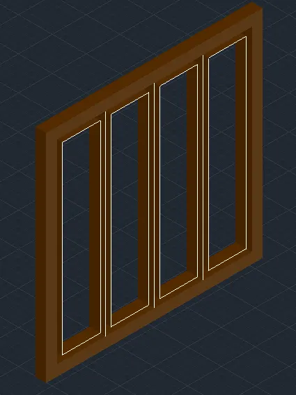
- Type 'EXT' in the command line and enter to get extrude tool
- Select the window and extrude 100mm in the y direction
- Type 'SU' in the command line and enter to get subtract tool
- Select the window frame and enter
- Select the mullions, glass panel and enter
- Type 'LA' in the command line and enter to get layers
- Create a new layer '3D Window-Mullion'
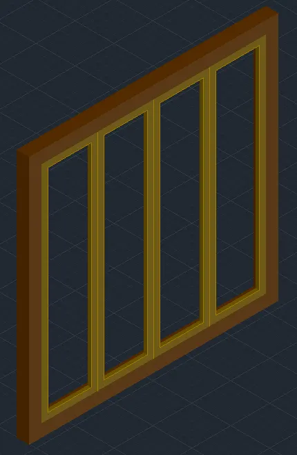
- Type 'EXT' in the command line and enter to get extrude tool
- Select the mullion and extrude 30mm in the y direction
- Type 'SU' in the command line and enter to get subtract tool
- Select the mullions and enter
- Select the glass panel and enter
- Type 'LA' in the command line and enter to get layers
- Create a new layer '3D Window-Glass'
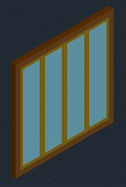
- Type 'EXT' in the command line and enter to get extrude tool
- Select the glass panel and extrude 15mm in the y direction
- Type 'M' in the command line and enter to get move tool
- Select the glass panel and paste it in the middle of the mullion
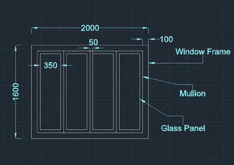
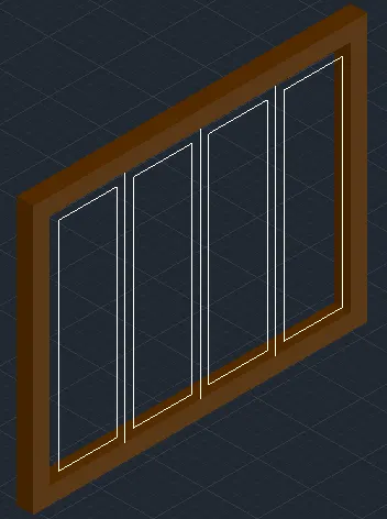
b) W2 (2000mmx1600mm)
- The window detail is given below
- Select layer '3D Window-Frame'
- Type 'EXT' in the command line and enter to get extrude tool
- Select the window and extrude 100mm in the y direction
- Type 'SU' in the command line and enter to get subtract tool
- Select the window frame and enter
- Select the mullions, glass panel and enter
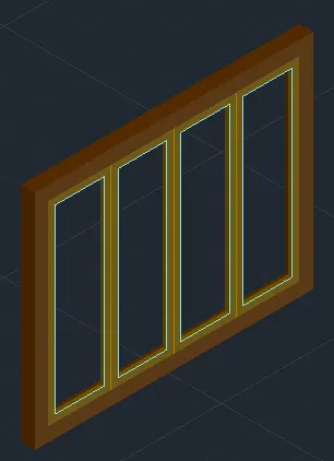
- Select layer '3D Window-Mullion'
- Type 'EXT' in the command line and enter to get extrude tool
- Select the mullion and extrude 30mm in the y direction
- Type 'SU' in the command line and enter to get subtract tool
- Select the mullions and enter
- Select the glass panel and enter
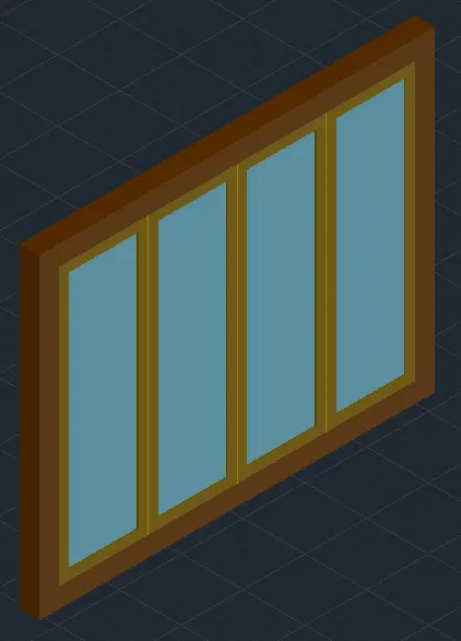
- Select layer '3D Window-Glass'
- Type 'EXT' in the command line and enter to get extrude tool
- Select the glass panel and extrude 15mm in the y direction
- Type 'M' in the command line and enter to get move tool
- Select the glass panel and paste it in the middle of the mullion
c) W3 (1500mmx2100mm)
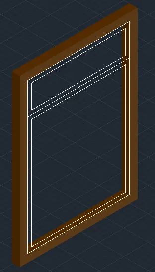
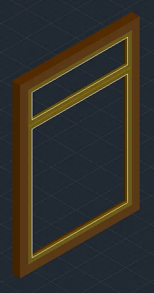
- The window detail is given below
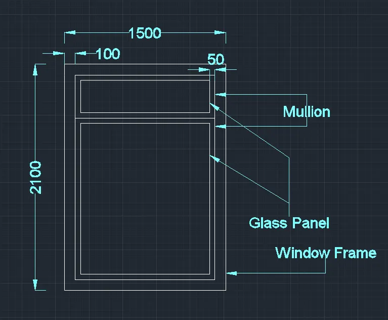
- Select layer '3D Window-Frame'
- Type 'EXT' in the command line and enter to get extrude tool
- Select the window and extrude 100mm in the y direction
- Type 'SU' in the command line and enter to get subtract tool
- Select the window frame and enter
- Select the mullions, glass panel and enter
- Select layer '3D Window-Mullion'
- Type 'EXT' in the command line and enter to get extrude tool
- Select the mullion and extrude 30mm in the y direction
- Type 'SU' in the command line and enter to get subtract tool
- Select the mullions and enter
- Select the glass panel and enter
- Select layer '3D Window-Glass'
- Type 'EXT' in the command line and enter to get extrude tool
- Select the glass panel and extrude 15mm in the y direction
- Type 'M' in the command line and enter to get move tool
- Select the glass panel and paste it in the middle of the mullion

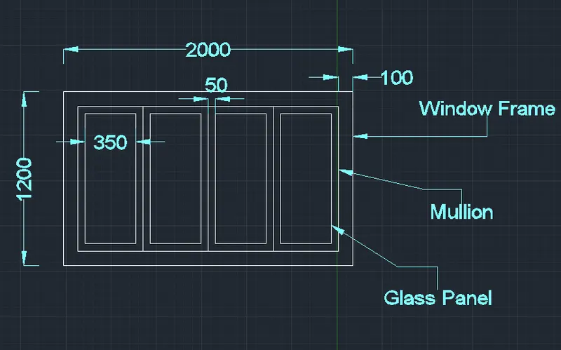
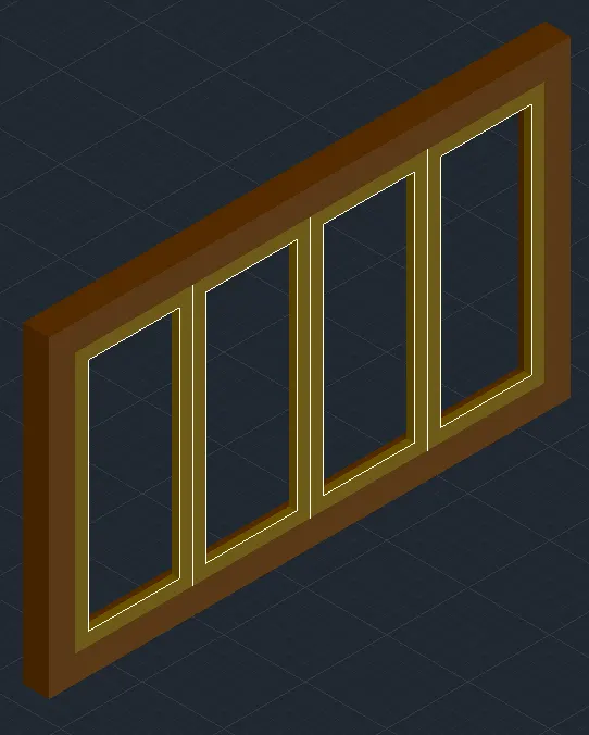
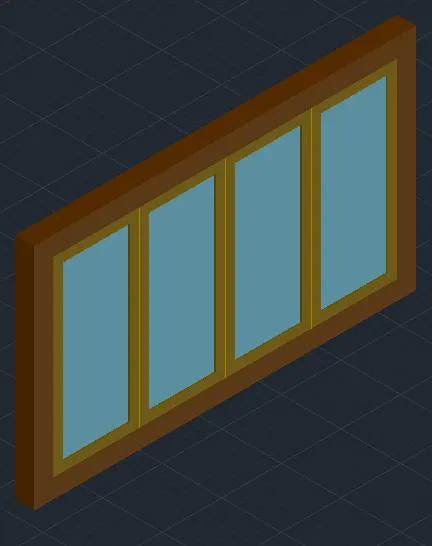
d) W4 (2000mmx1200mm)
- The window detail is given below
- Select layer '3D Window-Frame'
- Type 'EXT' in the command line and enter to get extrude tool
- Select the window and extrude 100mm in the y direction
- Type 'SU' in the command line and enter to get subtract tool
- Select the window frame and enter
- Select the mullions, glass panel and enter
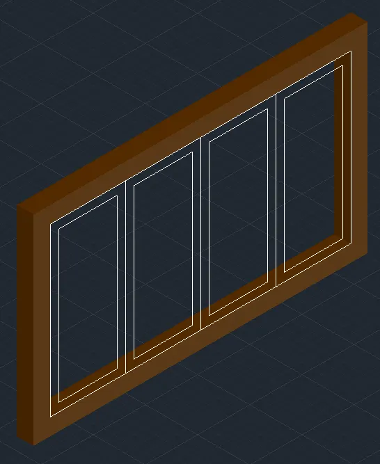
- Select layer '3D Window-Mullion'
- Type 'EXT' in the command line and enter to get extrude tool
- Select the mullion and extrude 30mm in the y direction
- Type 'SU' in the command line and enter to get subtract tool
- Select the mullions and enter
- Select the glass panel and enter
- Select layer '3D Window-Glass'
- Type 'EXT' in the command line and enter to get extrude tool
- Select the glass panel and extrude 15mm in the y direction
- Type 'M' in the command line and enter to get move tool
- Select the glass panel and paste it in the middle of the mullion
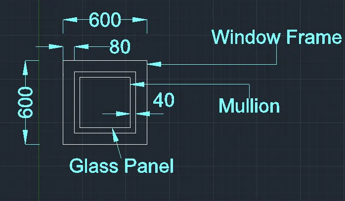
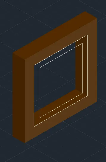
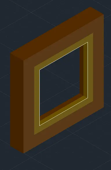
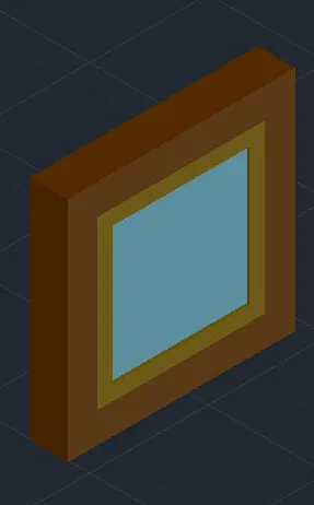
e) V (600mmx600mm)
- The window detail is given below
- Select layer '3D Window-Frame'
- Type 'EXT' in the command line and enter to get extrude tool
- Select the window and extrude 100mm in the y direction
- Type 'SU' in the command line and enter to get subtract tool
- Select the window frame and enter
- Select the mullions, glass panel and enter
- Select layer '3D Window-Mullion'
- Type 'EXT' in the command line and enter to get extrude tool
- Select the mullion and extrude 30mm in the y direction
- Type 'SU' in the command line and enter to get subtract tool
- Select the mullions and enter
- Select the glass panel and enter
- Select layer '3D Window-Glass'
- Type 'EXT' in the command line and enter to get extrude tool
- Select the glass panel and extrude 15mm in the y direction
- Type 'M' in the command line and enter to get move tool
- Select the glass panel and paste it in the middle of the mullion
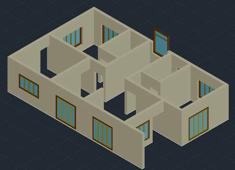
7. Place the window in the window space
- Type '3DROTATE' in the command line and enter to get 3d rotate tool
- Select the windows and rotate it according to the design
- Type 'CO' in the command line and enter to get copy tool
- Select the windows and place it in the window space
8. Create doors
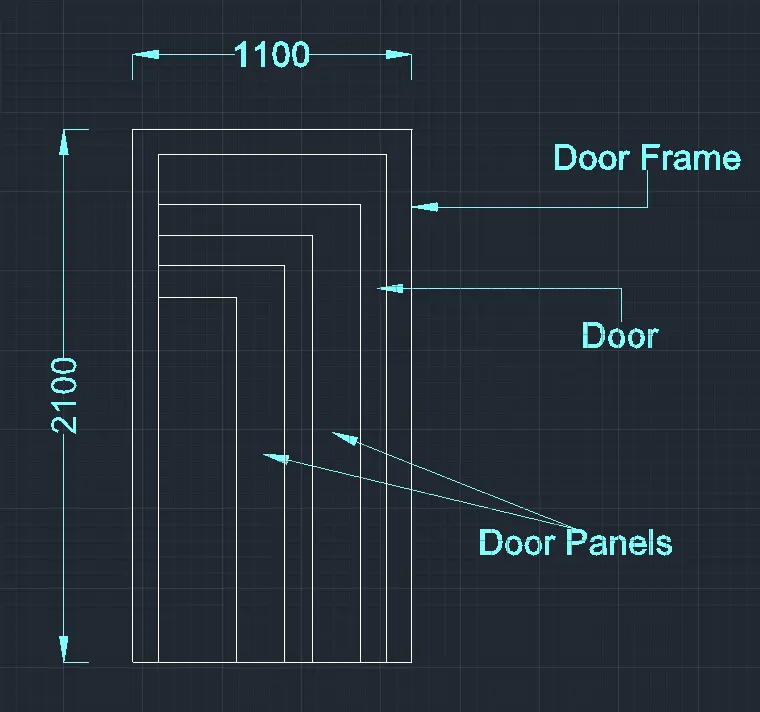
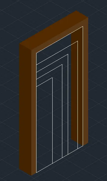
a) D1 (1100mmx2100mm)
- The door detail is given below
- Type 'LA' in the command line and enter to get layers
- Create a new layer '3D Door-Frame'
- Type 'EXT' in the command line and enter to get extrude tool
- Select the door frame and extrude 230mm in the y direction
- Type 'LA' in the command line and enter to get layers
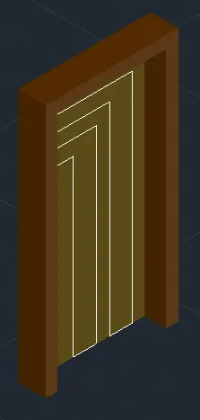
- Create a new layer '3D Door'
- Type 'EXT' in the command line and enter to get extrude tool
- Select the door and extrude 50mm in the y direction
- Type 'M' in the command line and enter to get move tool
- Select the door and paste it in the corner of the frame
- Type 'LA' in the command line and enter to get layers
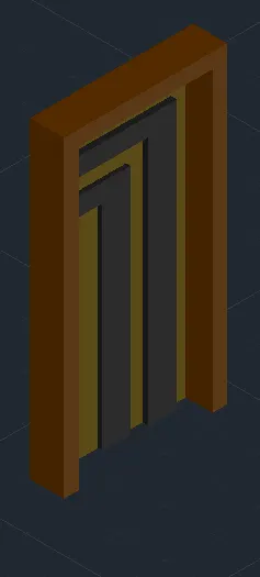
- Create a new layer '3D Door-Panel'
- Type 'EXT' in the command line and enter to get extrude tool
- Select the door panels and extrude 30mm and 40mm in the -y direction
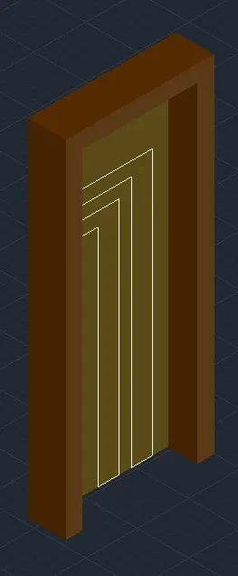
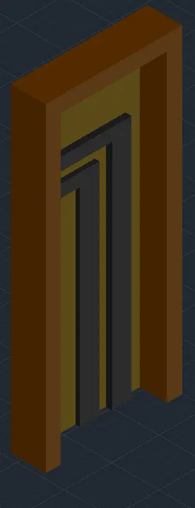
b) D2 (900mmx2100mm)
- The door detail is given below
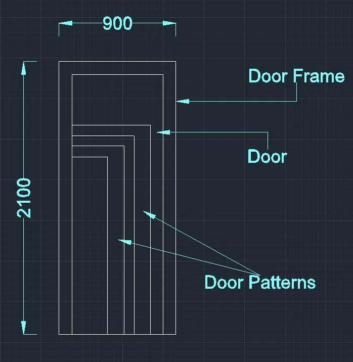
- Select layer '3D Door-Frame'
- Type 'EXT' in the command line and enter to get extrude tool
- Select the door frame and extrude 230mm in the -y direction
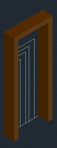
- Select layer '3D Door'
- Type 'EXT' in the command line and enter to get extrude tool
- Select the door and extrude 50mm in the -y direction
- Select layer '3D Door-Panel'
- Type 'EXT' in the command line and enter to get extrude tool
- Select the door panels and extrude 30mm and 40mm in the -y direction
c) D3 (800mmx2100mm)
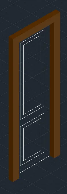
- The door detail is given below
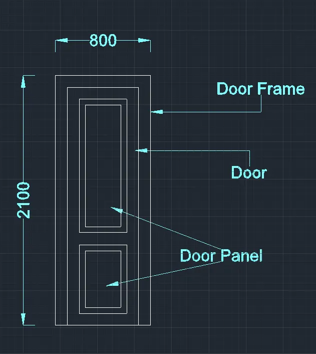
- Select layer '3D Door-Frame'
- Type 'EXT' in the command line and enter to get extrude tool
- Select the door frame and extrude 75mm in the -y direction
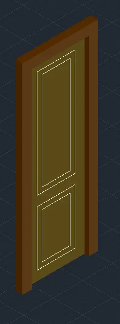
- Select layer '3D Door'
- Type 'EXT' in the command line and enter to get extrude tool
- Select the door and extrude 30mm in the -y direction
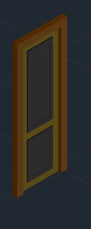
- Select layer '3D Door-Panel'
- Type 'EXT' in the command line and enter to get extrude tool
- Select the exterior door panels and extrude 20mm in the -y direction
- Select the interior door panels and extrude 20mm in the y direction
- Type 'SU' in the command line and enter to get subtract tool
- Select the exterior door panels and enter
- Select the interior door panels and enter
9. Place the door in the door space
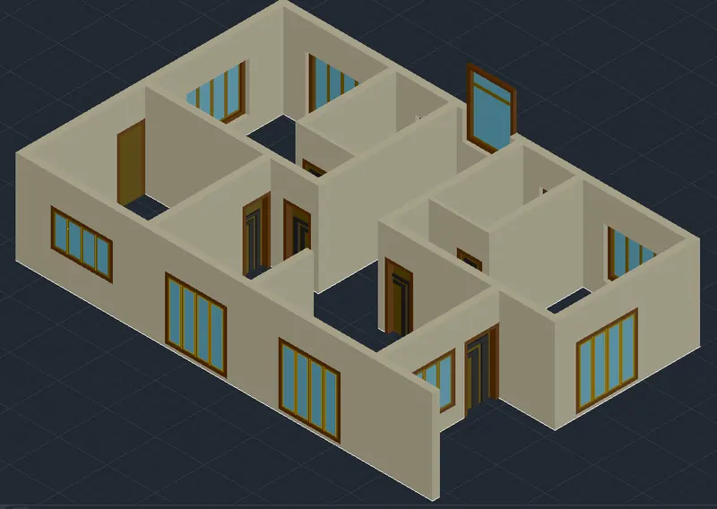
- Type '3DROTATE' in the command line and enter to get 3d rotate tool
- Select the doors and rotate it according to the design
- Type 'CO' in the command line and enter to get copy tool
- Select the doors and place it in the door space
10. Create plinth floor
- Type 'CO' in the command line and enter to get copy tool
- Select the ground floor plan outline and place it in some other place
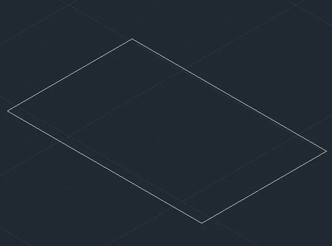
- Type 'OFF' in the command line and enter to get offset tool
- Select the necessary lines and offset 70mm outwards
- Type 'F' in the command line and enter to get fillet tool
- Fillet all the corners
- Type 'E' in the command line and enter to get erase tool
- Erase all unnecessary lines
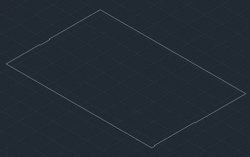
- Type 'LA' in the command line and enter to get layers
- Create a new layer '3D Plinth or Floor'
- Type 'EXT' in the command line and enter to get extrude tool
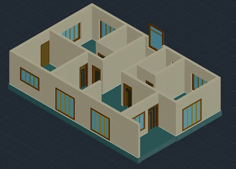
- Select the plinth floor and extrude 450mm in the z direction
- Type 'M' in the command line and enter to get move tool
- Select the plinth floor and paste it in the 3D elevation below the wall
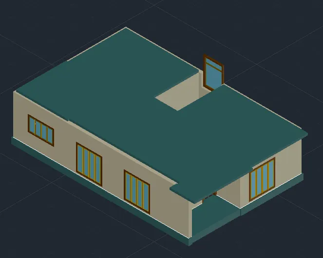
11. Create floor slab for first floor
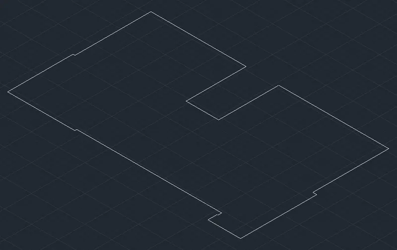
- Type 'CO' in the command line and enter to get copy tool
- Select the first floor plan and place it in some other place
- Type 'PLINE' in the command line and enter to get polyline tool
- Draw lines of first floor plan outline
- Type 'E' in the command line and enter to get erase tool
- Erase all unnecessary lines
- Select layer '3D Plinth or Floor'
- Type 'EXT' in the command line and enter to get extrude tool
- Select the floor slab and extrude 150mm in the z direction
- Type 'M' in the command line and enter to get move tool
- Select the floor slab and paste it in the 3D elevation above the wall
12. Create the 3D walls for first floor
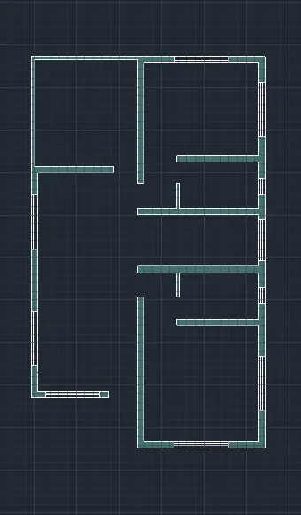
- Select layer '3D Wall'
- Type 'CO' in the command line and enter to get copy tool
- Select the first floor plan and paste it in some other place for extrution
- Type 'BO' in the command line and enter to get boundary creation tool
- Select 'Region' as Object type
- Pick all the wall regions
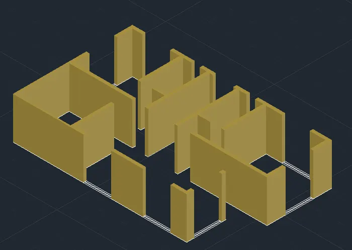
- Type 'EXT' in the command line and enter to get extrude tool
- Select the walls and extrude 3000mm in the z direction
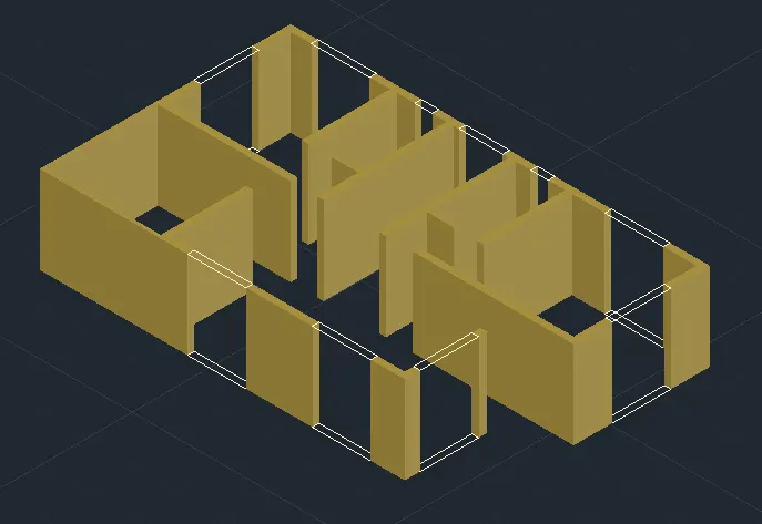
13. Create window openings
- Type 'REC' in the command line and enter to get rectangle
- Draw a rectangle on top and bottom of every windows in the plan
a) W1 (2000mmx2000mm)
- Type 'EXT' in the command line and enter to get extrude tool
- Select the bottom rectangle and extrude 100mm in the z direction
- Select the top rectangle and extrude 900mm in the -z direction
b) W2 (2000mmx1600mm)
- Type 'EXT' in the command line and enter to get extrude tool
- Select the bottom rectangle and extrude 500mm in the z direction
- Select the top rectangle and extrude 900mm in the -z direction
c) W3 (1500mmx2100mm)
- Type 'EXT' in the command line and enter to get extrude tool
- Select the top rectangle and extrude 1800mm in the -z direction
d) V (600mmx600mm)
- Type 'EXT' in the command line and enter to get extrude tool
- Select the bottom rectangle and extrude 1500mm in the z direction
- Select the top rectangle and extrude 900mm in the -z direction
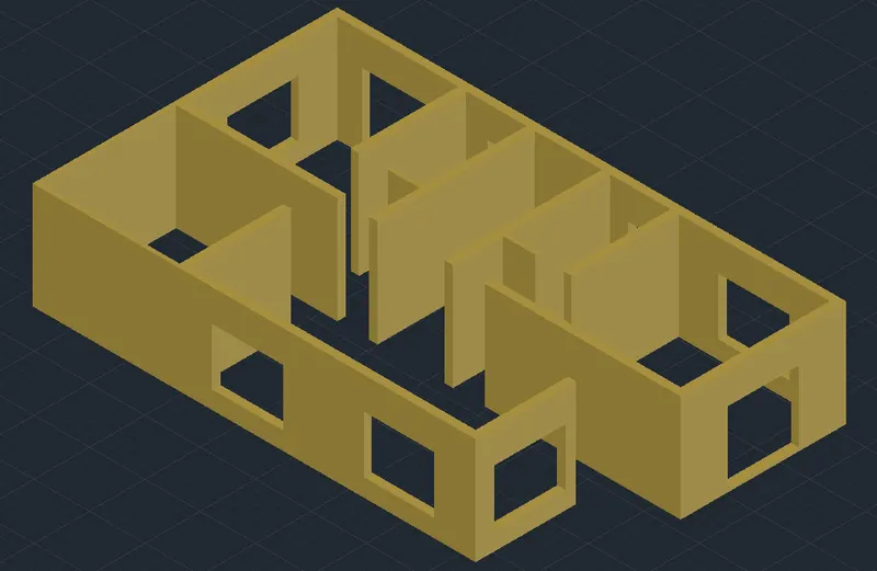
14. Create door openings
- Type 'REC' in the command line and enter to get rectangle
- Draw a rectangle on top of every doors in the plan
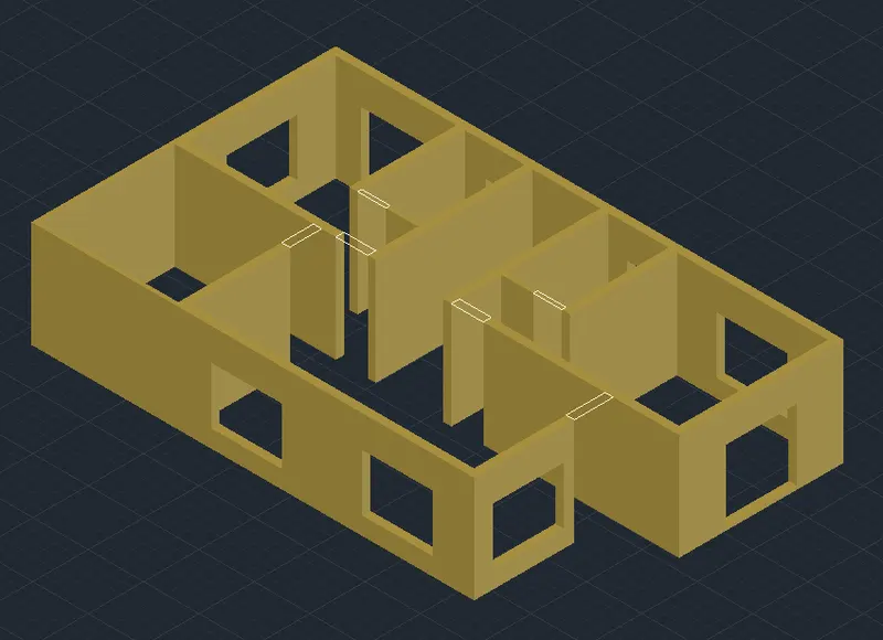
- Type 'EXT' in the command line and enter to get extrude tool
- Select the top rectangle and extrude 900mm in the -z direction
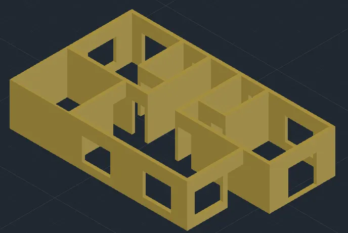
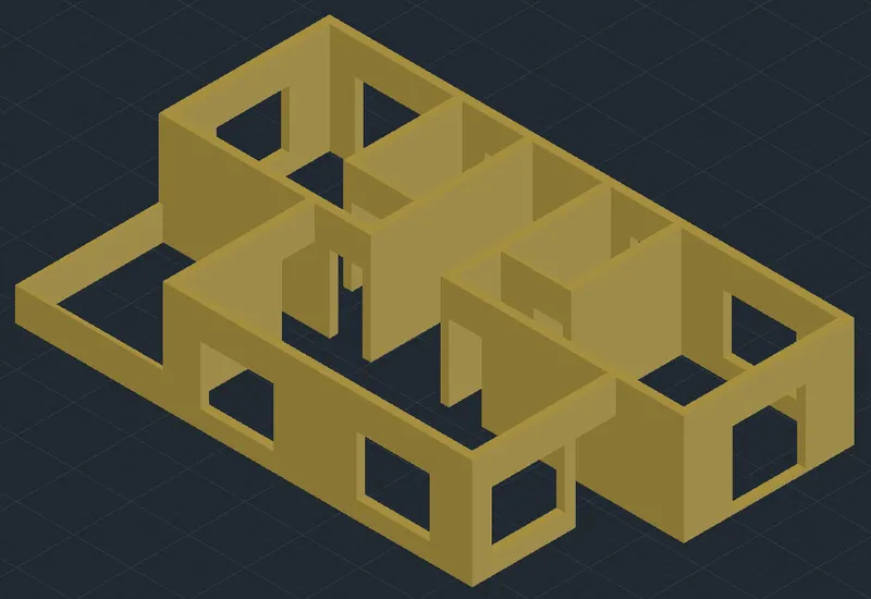
15. Create parapet wall for terrace
- Type 'PLINE' in the command line and enter to get polyline tool
- Draw lines on the parapet wall on the terrace
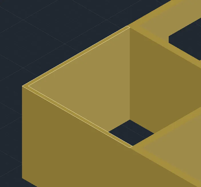
- Type 'EXT' in the command line and enter to get extrude tool
- Select the parapet wall and extrude 2100mm in the -z direction
- Type 'SU' in the command line and enter to get subtract tool
- Select the main wall and enter
- Select the parapet wall and enter
 \
\
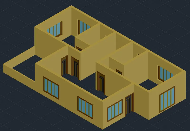
16. Place the windows and doors in the window and door space
- Type '3DROTATE' in the command line and enter to get 3d rotate tool
- Select the windows, doors and rotate it according to the design
- Type 'CO' in the command line and enter to get copy tool
- Select the windows, doors and place it in the window and door space
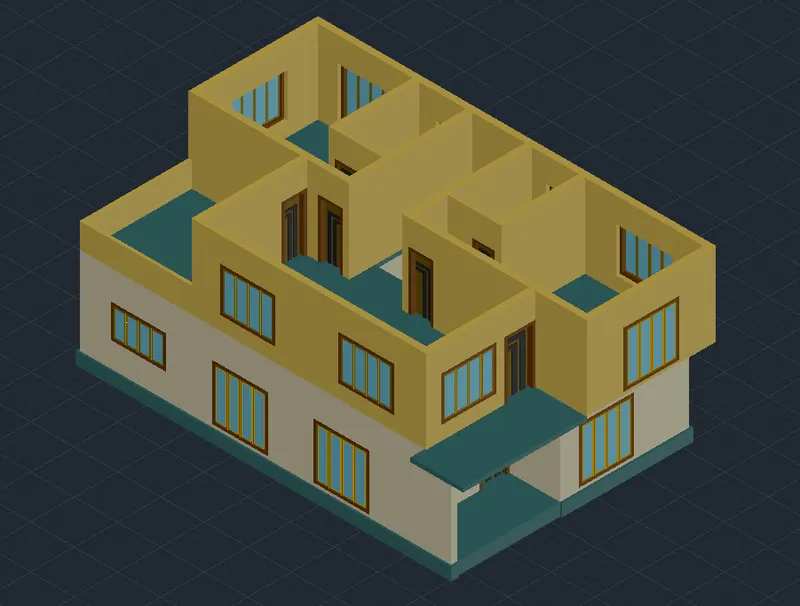
17. Place the first floor above the ground floor
- Type 'M' in the command line and enter to get move tool
- Select the first floor and paste it in the 3D elevation above the floor slab
- Type 'PRESSPULL' in the command line and enter to get presspull tool
- Presspull the ground floor wall upto to the bottom of the first floor wall
18. Create stairs
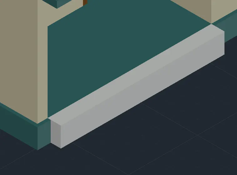
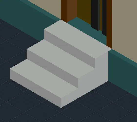
a) Front entrance stairs
- Type 'LA' in the command line and enter to get layers
- Create a new layer '3D Stairs'
- Type 'REC' in the command line and enter to get rectangle
- Draw a rectangle of size 3700mmx450mm on the plinth of 3D elevation
- Type 'EXT' in the command line and enter to get extrude tool
- Select the rectangle and extrude 300mm in the -z direction
- Type 'REC' in the command line and enter to get rectangle
- Draw a rectangle of size 3700mmx300mm on the bottom plinth of 3D elevation
- Type 'EXT' in the command line and enter to get extrude tool
- Select the rectangle and extrude 300mm in the -z direction
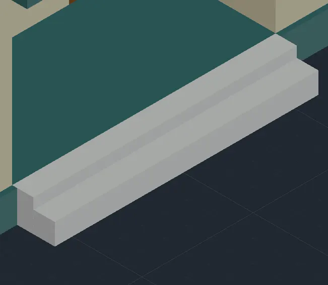
- Type 'REC' in the command line and enter to get rectangle
- Draw a rectangle of size 3700mmx150mm on the bottom plinth of 3D elevation
- Type 'EXT' in the command line and enter to get extrude tool
- Select the rectangle and extrude 300mm in the -z direction
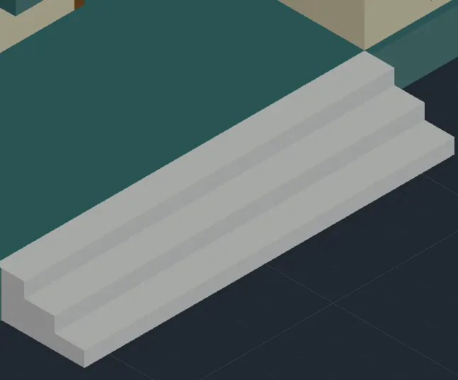
- Type 'UNI' in the command line and enter to get union tool
- Select the steps and enter
b) Back entrance stairs
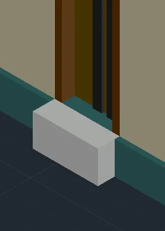
- Type 'REC' in the command line and enter to get rectangle
- Draw a rectangle of size 900mmx450mm on the plinth of 3D elevation
- Type 'EXT' in the command line and enter to get extrude tool
- Select the rectangle and extrude 300mm in the -z direction
- Type 'REC' in the command line and enter to get rectangle
- Draw a rectangle of size 900mmx300mm on the bottom plinth of 3D elevation
- Type 'EXT' in the command line and enter to get extrude tool
- Select the rectangle and extrude 300mm in the -z direction
- Type 'REC' in the command line and enter to get rectangle
- Draw a rectangle of size 900mmx150mm on the bottom plinth of 3D elevation
- Type 'EXT' in the command line and enter to get extrude tool
- Select the rectangle and extrude 300mm in the -z direction
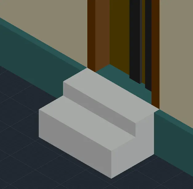
- Type 'UNI' in the command line and enter to get union tool
- Select the steps and enter
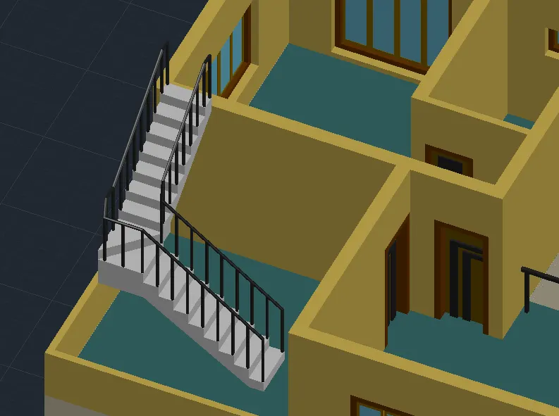
c) Inside stair
- Type 'REC' in the command line and enter to get rectangle
- Draw a rectangle of size 300mmx950mm
- Type 'EXT' in the command line and enter to get extrude tool
- Select the rectangle and extrude 150mm in the -z direction
- Type 'CO' in the command line and enter to get copy tool
- Select the step and place it above for 10 times
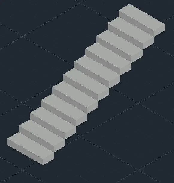
- Type 'PRESSPULL' in the command line and enter to get presspull tool
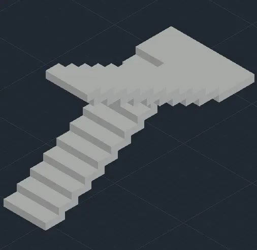
- Presspull the back of the steps 150mm in the x direction
- Presspull the back of the 11th step 510mm in the x direction
- Presspull the right of the 11th step 950mm in the -y direction
- Type 'CO' in the command line and enter to get copy tool
- Select the 1st 10 steps and place it above first flight
- Type '3DROTATE' in the command line and enter to get 3d rotate tool
- Select the stair and rotate it according to the design
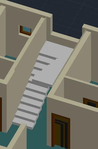
- Type 'M' in the command line and enter to get move tool
- Select the stair and place it in the 3D elevation inside the building as per design
- Type 'LA' in the command line and enter to get layers
- Create a new layer '3D Rails'
- Type 'REC' in the command line and enter to get rectangle
- Draw a rectangle of size 50mmx60mm on the 1st step
- Type 'EXT' in the command line and enter to get extrude tool
- Select the rectangle and extrude 900mm in the -z direction
- Type 'CO' in the command line and enter to get copy tool
- Select the rail and paste it according to the desired design
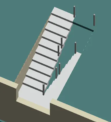
- Type 'PLINE' in the command line and enter to get polyline tool
- Draw polylines connecting all the rails
- Type 'REC' in the command line and enter to get rectangle
- Draw a rectangle of size 60mmx60mm
- Type 'SWEEP' in the command line and enter to get sweep tool
- Select the rectangle 60mmx60mm and enter
- Select the polylines as the path
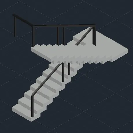
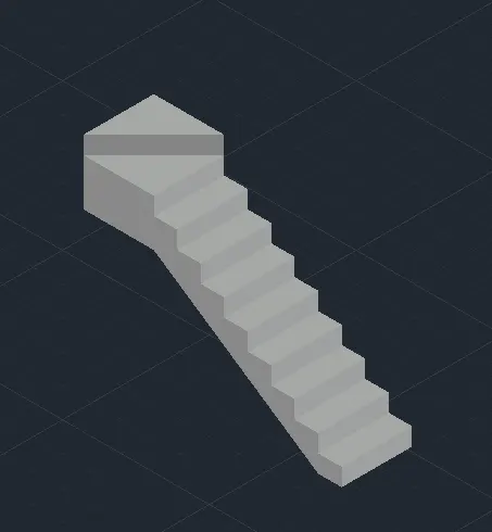
d) Terrace stair
- Select layer '3D Stairs'
- Type 'L' in the command line and enter to get line
- Draw a line 187.5mm in the z direction and 250mm in the y direction
- Type 'CO' in the command line and enter to get copy tool
- Select the lines and paste it above 6 times
- Type 'L' in the command line and enter to get line
- Draw lines 187.5mm in the z direction and 750mm in the y direction
- Draw lines 500mm in the -z direction and 750mm in the -y direction
- Draw a line 250mm from bottom step in the y direction
- Draw a line connecting bottom line and top point
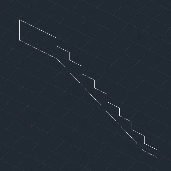
- Select all the lines, type 'J' and enter
- Type 'EXT' in the command line and enter to get extrude tool
- Select the lines and extrude 750mm in the x direction
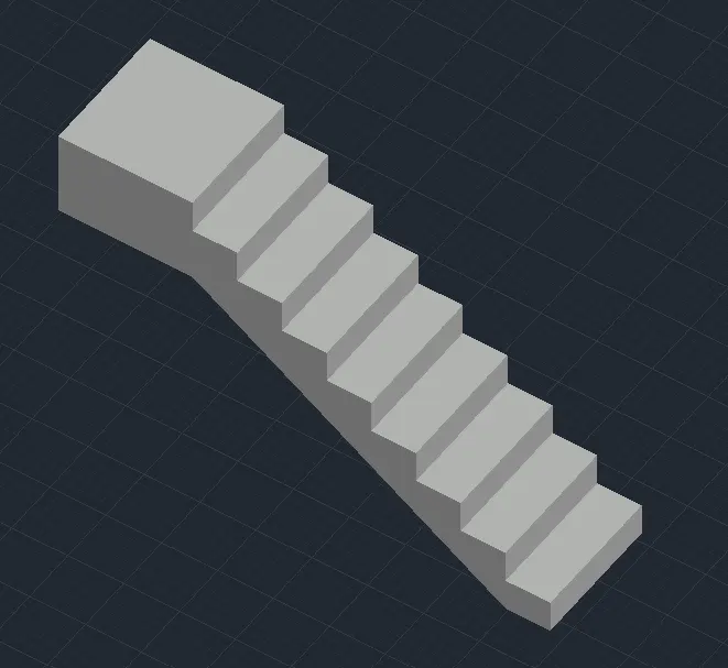
- Type 'L' in the command line and enter to get line
- Draw lines to form a triangle at the top step
- Select the lines, type 'J' and enter
- Type 'EXT' in the command line and enter to get extrude tool
- Select the lines and extrude 187.5mm in the z direction
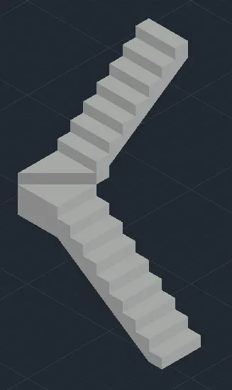
- Type 'L' in the command line and enter to get line
- Draw a line 187.5mm in the z direction and 250mm in the x direction
- Type 'CO' in the command line and enter to get copy tool
- Select the lines and paste it above 6 times
- Type 'L' in the command line and enter to get line
- Draw a line 270mm in the -z direction
- Draw lines 187.5mm from bottom step in the -z direction and 250mm in the x direction
- Draw a line connecting bottom line and top point
- Select all the lines, type 'J' and enter
- Type 'EXT' in the command line and enter to get extrude tool
- Select the lines and extrude 750mm in the -y direction
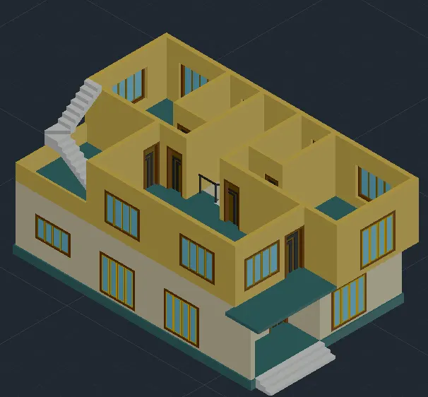
- Type 'M' in the command line and enter to get move tool
- Select the stair and place it in the 3D elevation inside the building as per design
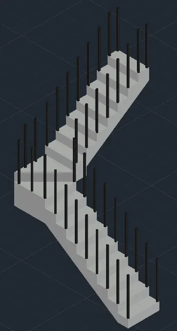
- Select layer '3D Rails'
- Type 'CYL' in the command line and enter to get cylinder tool
- Extrude a cylider 900mm with a radius 25mm
- Type 'CO' in the command line and enter to get copy tool
- Select the cylinder and paste it on every steps accordingly
- Type 'PLINE' in the command line and enter to get polyline tool
- Draw polylines connecting all the rails
- Type 'C' in the command line and enter to get circle
- Draw a circle of radius 25mm
- Type 'SWEEP' in the command line and enter to get sweep tool
- Select the circle and enter
- Select the polylines as the path
19. Create floor slab for first floor
- Type 'CO' in the command line and enter to get copy tool
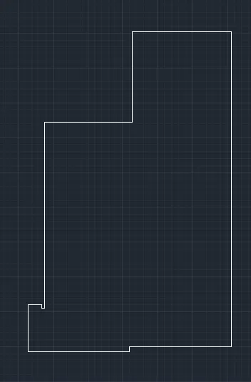
- Select the second floor plan and place it in some other place
- Type 'PLINE' in the command line and enter to get polyline tool
- Draw lines of second floor plan outline
- Type 'E' in the command line and enter to get erase tool
- Erase all unnecessary lines
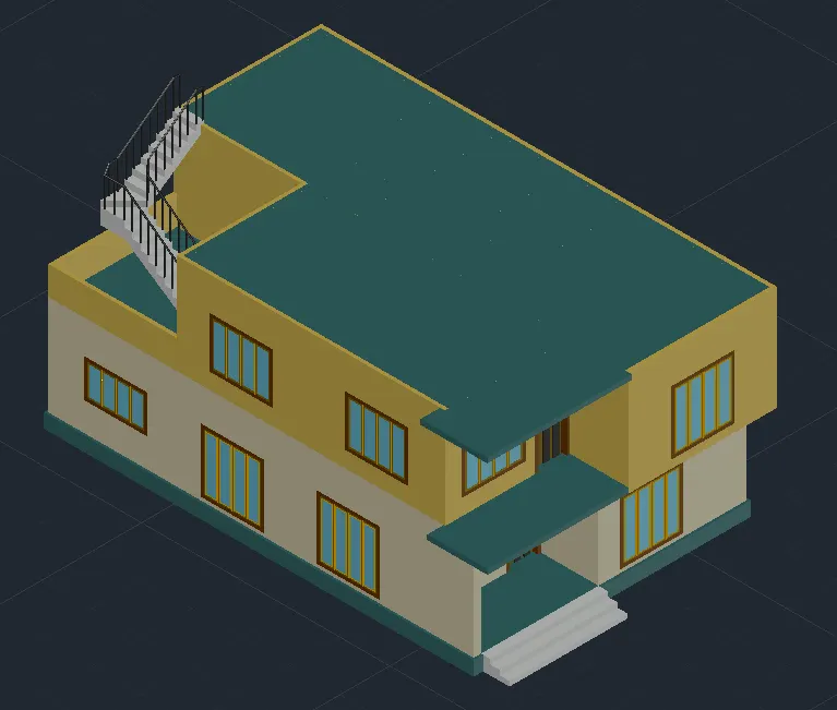
- Select layer '3D Plinth or Floor'
- Type 'EXT' in the command line and enter to get extrude tool
- Select the floor slab and extrude 150mm in the z direction
- Type 'M' in the command line and enter to get move tool
- Select the floor slab and paste it in the 3D elevation above the wall
20. Create pergola in the balcony
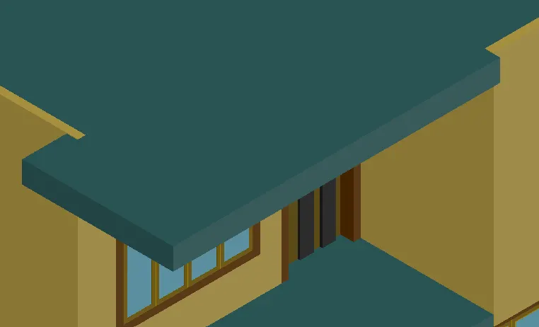
- Type 'PLINE' in the command line and enter to get polyline tool
- Draw lines on upper floor slab of balcony for extrude
- Type 'EXT' in the command line and enter to get extrude tool
- Select the balcony floor slab and extrude 150mm in the -z direction
- Type 'REC' in the command line and enter to get rectangle
- Draw a rectangle of size 400mmx1150mm on the floor slab
- Type 'CO' in the command line and enter to get copy tool
- Select the rectangle and place it with a distance of 400mm between each
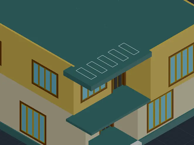
- Type 'PRESSPULL' in the command line and enter to get presspull tool
- Presspull the pargolas 300mm in the -z direction
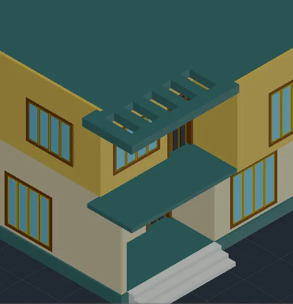
21. Create parapet wall above first floor
- Type 'CO' in the command line and enter to get copy tool
- Select the second floor plan and place it in some other place
- Type 'PLINE' in the command line and enter to get polyline tool
- Draw lines of second floor plan outline of parapet
- Type 'F' in the command line and enter to get fillet tool
- fillet all corner lines
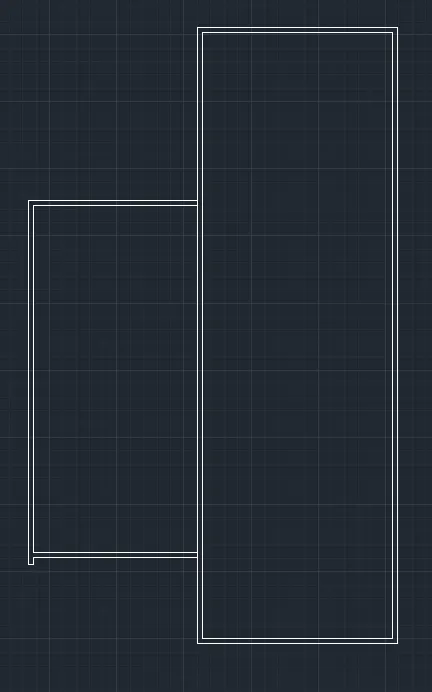
- Type 'EXT' in the command line and enter to get extrude tool
- Select the left side parapet and extrude 600mm in the z direction
- Select the right side parapet and extrude 900mm in the z direction
- Type 'M' in the command line and enter to get move tool
- Select the parapet walls and paste it in the 3D elevation above the wall in the first floor
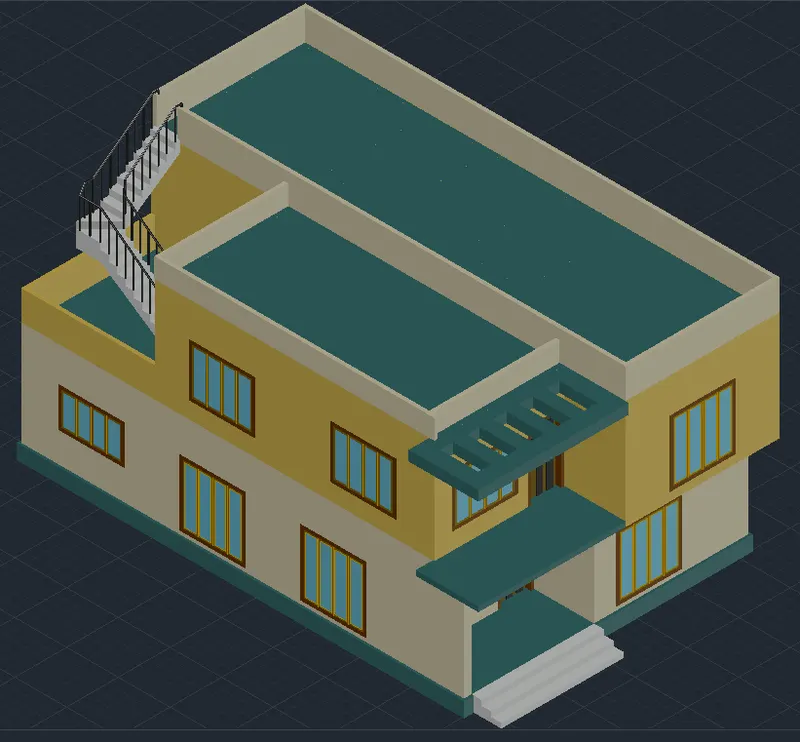
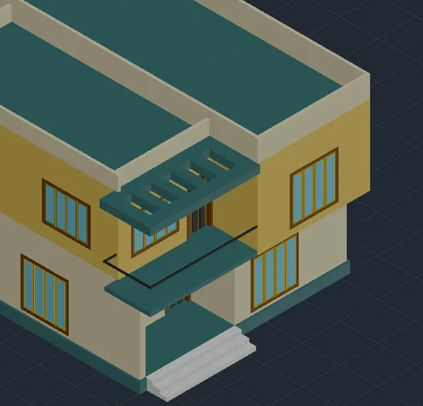
22. Create balcony rails and glass
- Select layer '3D Rails'
- Type 'REC' in the command line and enter to get rectangle
- Draw a rectangle of size 60mmx50mm on the wall
- Type 'EXT' in the command line and enter to get extrude tool
- Select the rectangle and extrude 4450mm in the -x direction
- Type 'REC' in the command line and enter to get rectangle
- Draw a rectangle of size 60mmx50mm on the end of the rail
- Type 'EXT' in the command line and enter to get extrude tool
- Select the rectangle and extrude 1900mm in the y direction
- Type 'REC' in the command line and enter to get rectangle
- Draw a rectangle of size 60mmx50mm on the end of the new rail
- Type 'EXT' in the command line and enter to get extrude tool
- Select the rectangle and extrude 520mm in the x direction
- Type 'LA' in the command line and enter to get layers
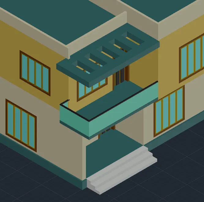
- Create a new layer '3D Glass Panel'
- Type 'REC' in the command line and enter to get rectangle
- Draw rectangles inside the rail
- Type 'EXT' in the command line and enter to get extrude tool
- Select the rectangles and extrude 15mm inside the rails
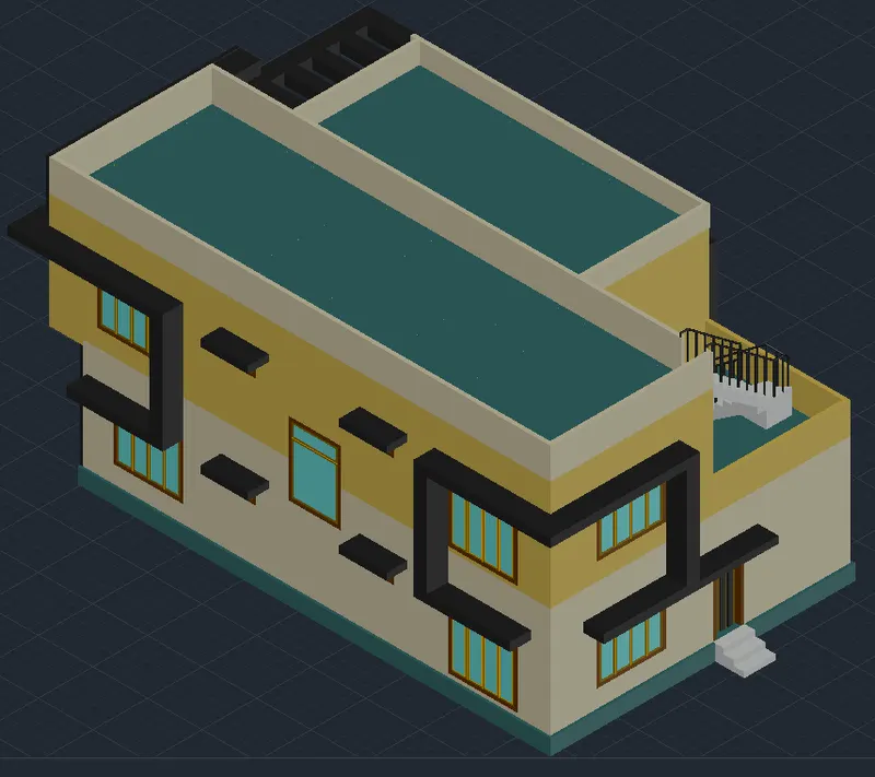
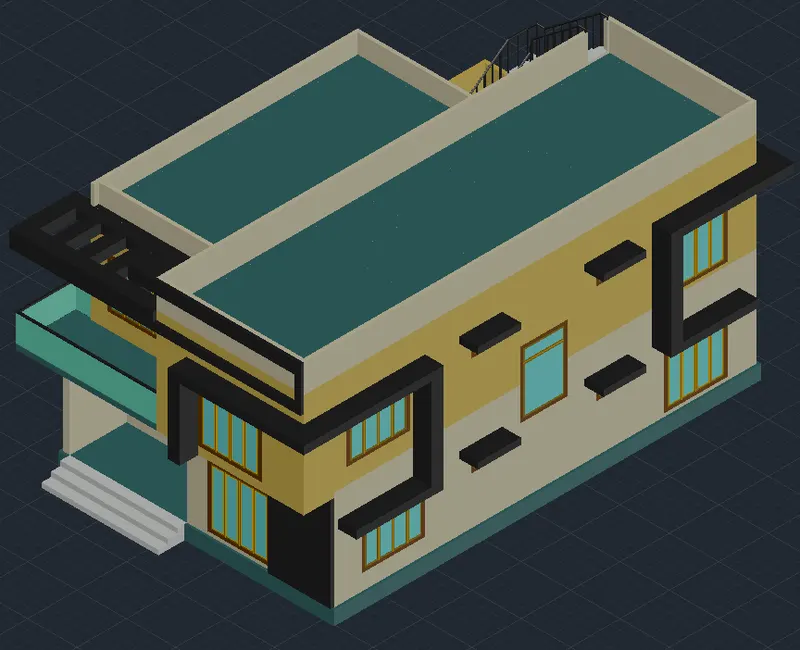
23. Create exterior designs and sunshades
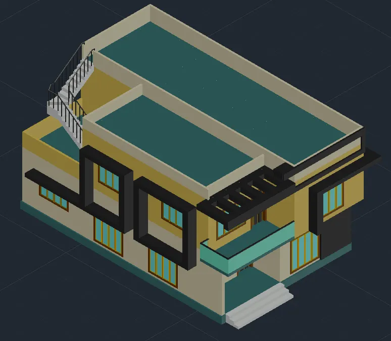
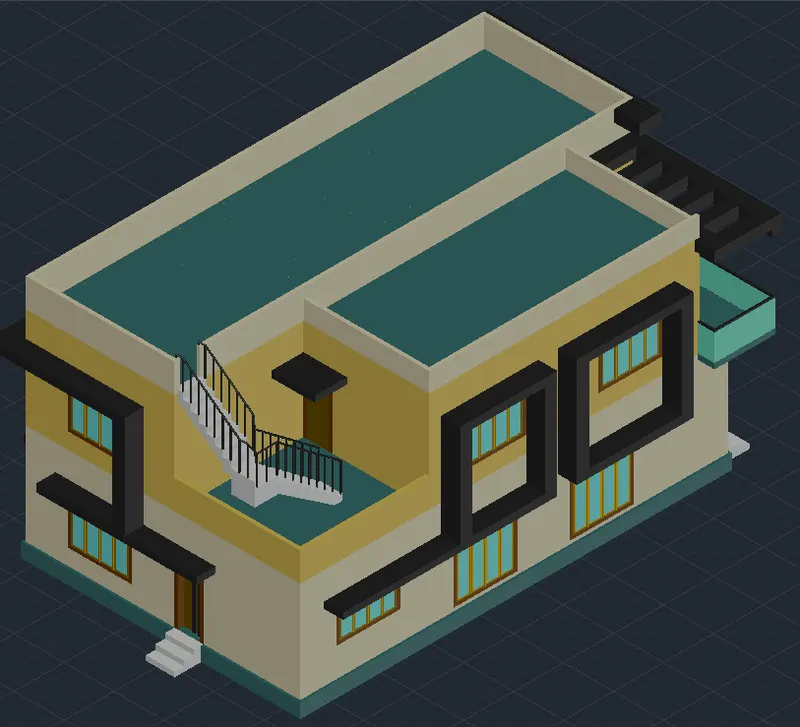
- Type 'LA' in the command line and enter to get layers
- Create a new layer '3D Projections or Sunshades'
- Type 'REC' in the command line and enter to get rectangle
- Draw rectangles according to the desired design for sunshades and projections
- Type 'EXT' in the command line and enter to get extrude tool
- Select the rectangles for design and extrude 100mm outside of the wall
- Select the rectangles for designed sunshades and extrude 600mm outside of the wall
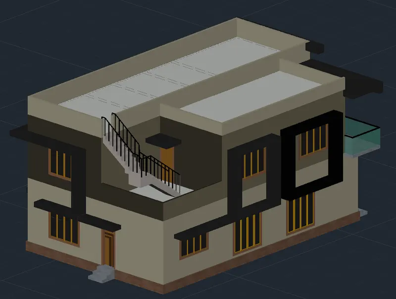
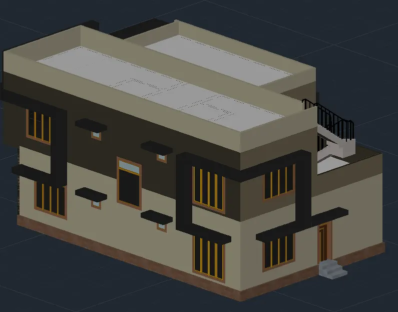
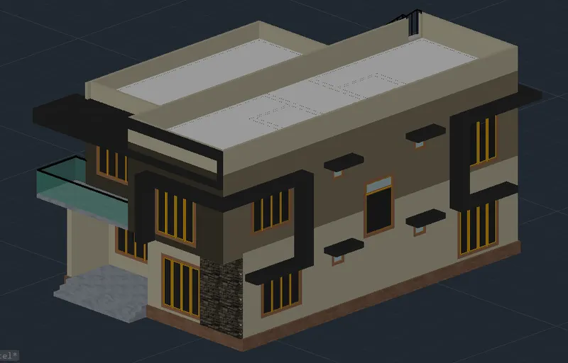
24. Provide material texture to 3D objects
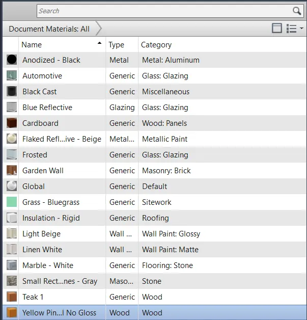
- In 'Visualize' tab, click on the 'Material Browser'
- Assign different materials to different objects
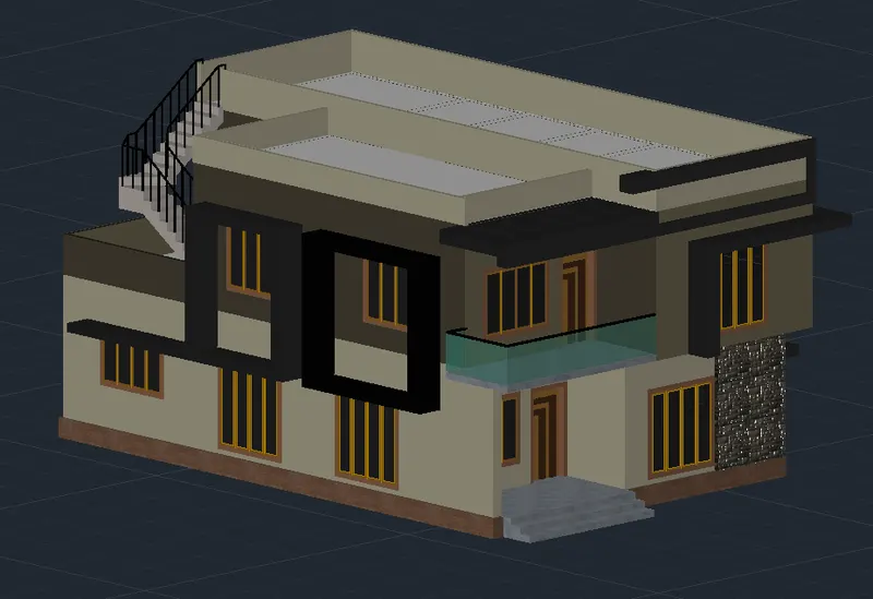
- Materials used in this building and the result is given below
25. Provide lighting for the building
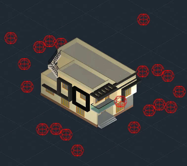
- In 'Visualize' tab, click on the 'Create Light'
- Assign lights outside the building brighten the exterior of the building
26. Rendering
- Type 'RR' in the command line and enter to get rendering option
- Rendering is done using viewport with low quality
- Rendered final output is shown the results
RESULT
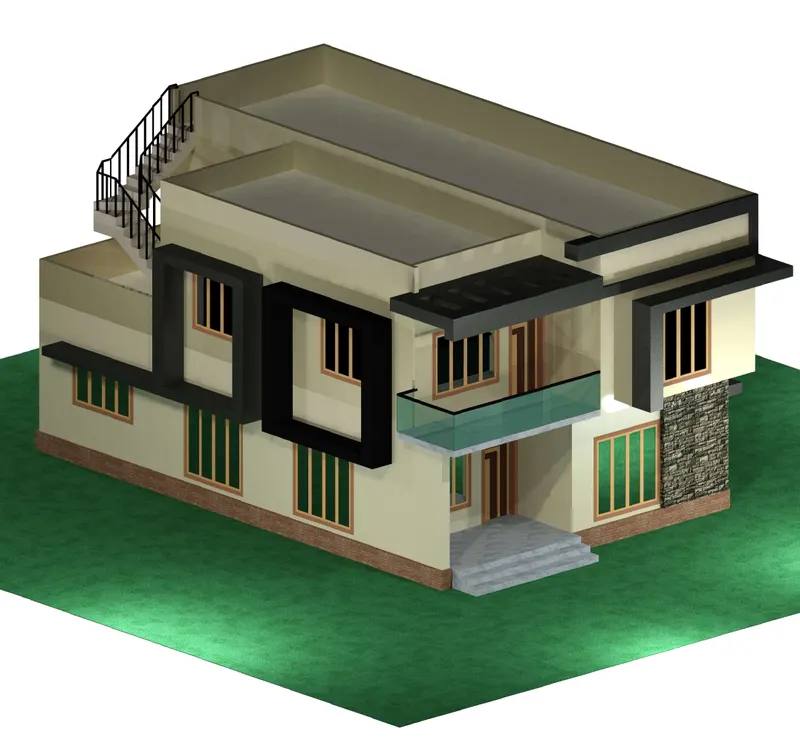
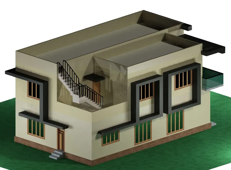
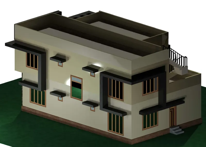
The 3D rendered model for a residential building is created in AutoCad. The different rendered 3D view of the residential building is shown below
a) S-W View
b) N-W view
c) N-E View
d) S-E view