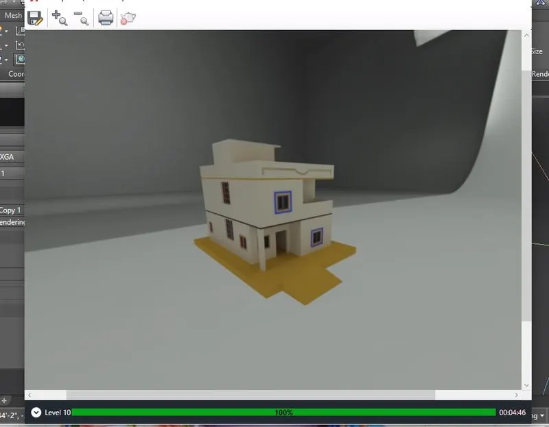
Project 2_Creating a 3D rendered model for a Residential Building in AutoCad
AIM:Creating a 3D rendered model for a Residential Building in AutoCad
INTRADUCTION:
Draw a residential building using AUTOCAD application. autocad is designing and drafting software we cn do renderings also done by this software using commands in autocad,
2D COMMANDS:
- LINE
- CIRCLE
- RECTANGLE
- TRIM
- EXTEND
- POLYLINE
- ARC
- MIRROR
- COPY
- MOVE
- SCALE
- FILLET
- STRECH
- JOIN
- ROTATE
- ARRAY
- LAYER
- DIM
- REGION
- CONSTRACTION LINE
3D COMMADS:
- EXTRUDE
- REGION
- BOUNDARY
- UNION
- SUBTRACT
- SLICE
- LAYERS
- SWEEP
- SPLIE
- SUFACE
- UCS
- 3D ROTATE
- 3D ORBIT
- 3D MIRROR
- 3D MOVE
- 3DFACE
- SOLID EDIT
- REVOLVE
PROCEDURE:
STEP-1:
- Open new drawig file in autocad
- set the units in ENGINEERING
- set the limax 100',100'
- enable the tools in 3d modeling in autocad
- enable the view cube
STEP-2:
- Select the rec command 1st point as a 10',10'
- draw a rectangle @40',30'
- explode the rectangle and offset the set back distances.
- 3 sides setback distances as a 4'.
- except front side as 7'
- created buidup area in center rectangle.
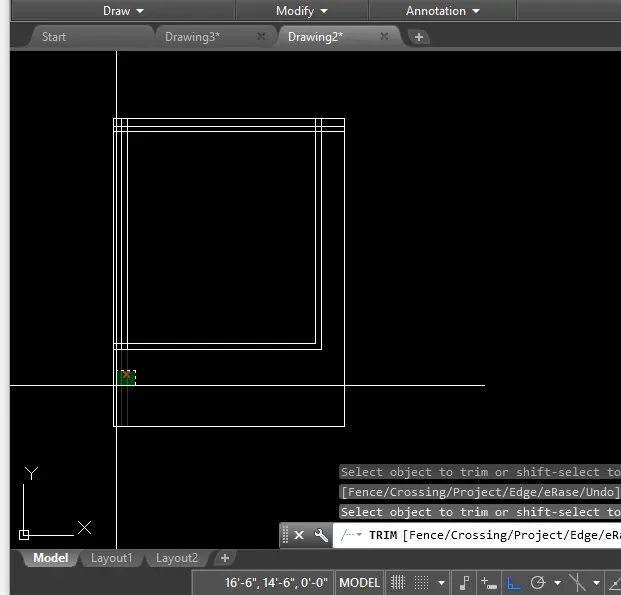
- using trim command erase the unwanted lines
- offset the internal buldup area line with 9" for the wall thickness provided
- provide the internal partisions with thickness of 4.5".
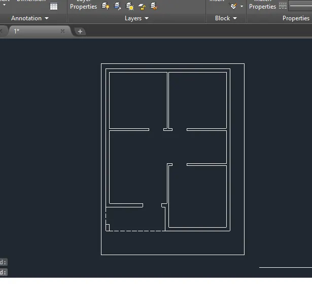
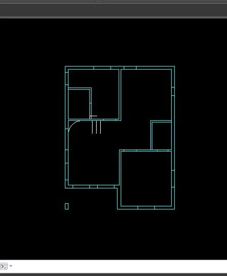
- trim door points using trim command
- created layers prefore every item incuded differently
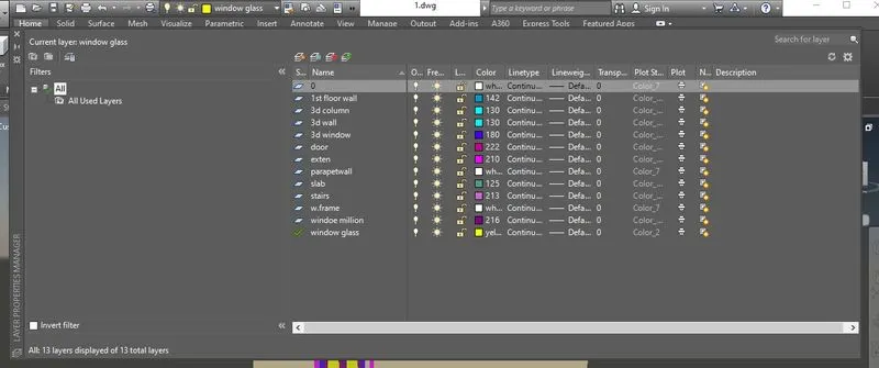
- using BO command boundary the walls to region
- enter BO command select region < pick poin < select region elements internal points < enter region created.
- now EXTRUDE the walls with the height of 10'4"
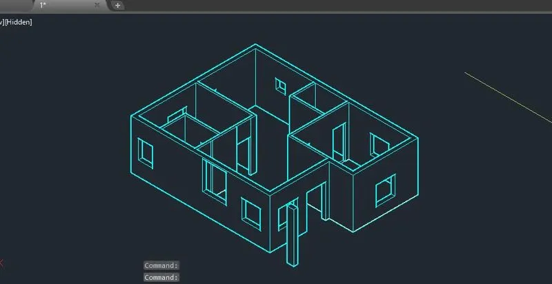
- using UCS command cut the windows. UCS < SELECT PLAN < CURRENT PLAN
- now use the subtract command to cut the walls SUBTRACT< SELECT OBJECT EXCEPT BEFORE EXTRACTED < SELECT EXTRUDED WINDOW < ENTER WINDOW IS CREATED
- select UCS command point the ucs in top surface of walls with XY DIRECTIONAL select line command draw rectangle in required field
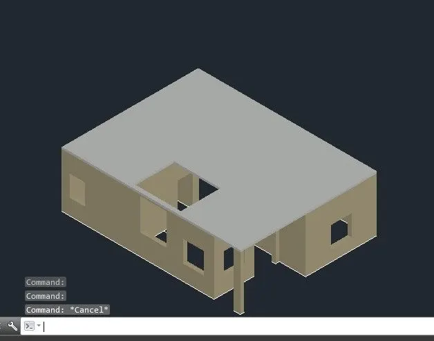
- now provide stair case loft in slab from bottom
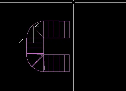
- draw a stair case with line command
- now draw the indivisvaly each step and add required point useing move command in 3D farmet.
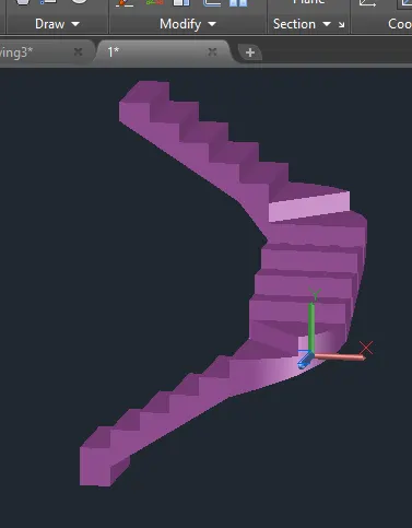
- enter shaded farmet we get these type of shaded images shade < shade enter
- place the sair case in the plan
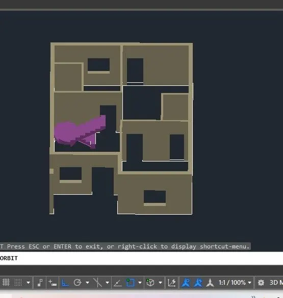
- these same proceduretill the hed room
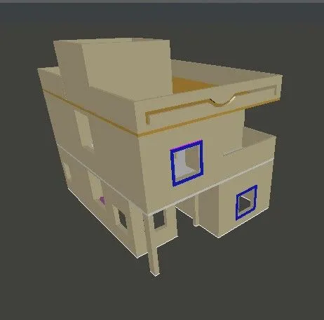
- elevation designes are added through the SOLIDEDIT command
- now created windows using UCS command place wall facing of where we place a window
- now select rectangle place in filed of place window
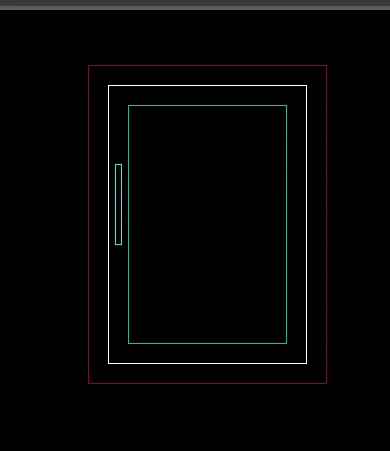
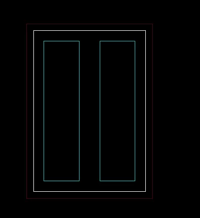
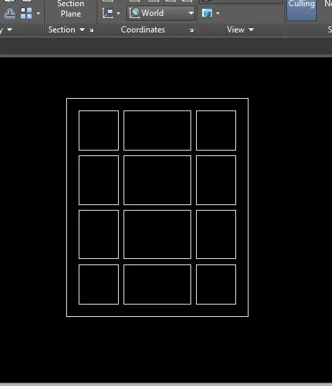
- these different types windows used in in the project
- region these windows in 2d farmet and extrude window frame as a 4" window million as a 3" and glass thickness as 0.5"
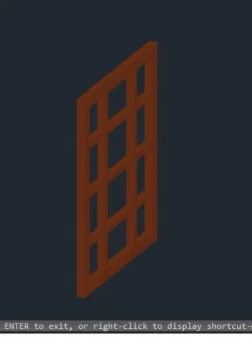
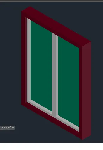
- place these windows in prefored possition
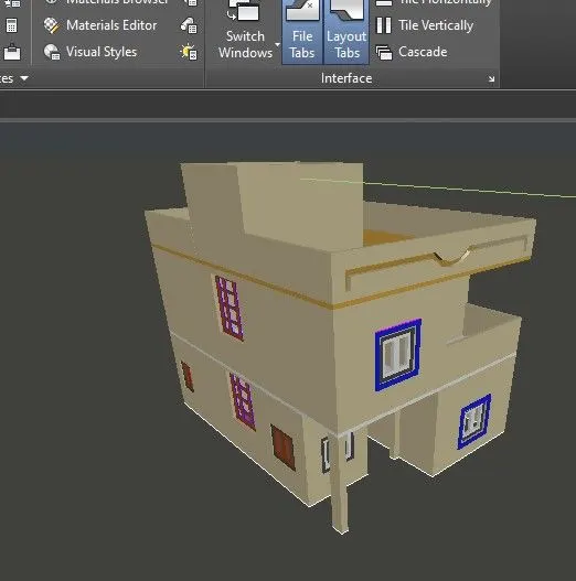
- now add cemera in required point visuvalize < cemera

- select cemera
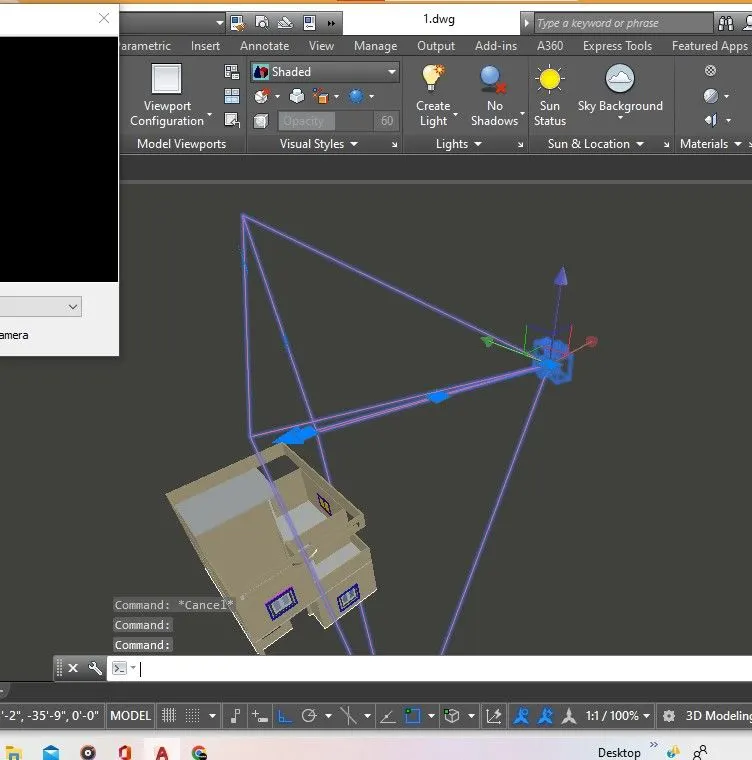
- select visuvalize tab to add lighting as natural and enable shadows
- then go towards rendering the image select render in visuvalize tab render
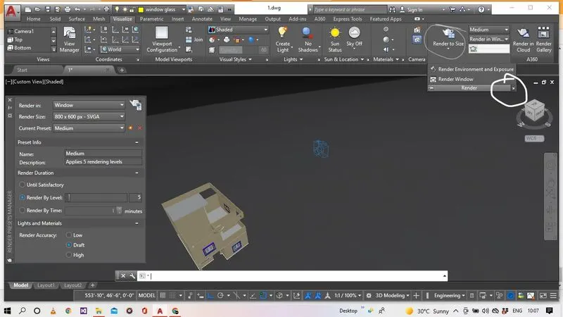
- enable render enivironmental and exposure.
- select render size, qulity, rendering levels, render accuracy and name of render.
- procede to wards render the image.
RESULTS: