Drafting of various geometries using Chamfer, Fillet tool in AutoCad
AIM 1: To draw the given drawing in autocad.
PROCEDURE:
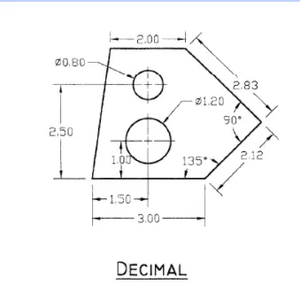
Step:1
- select new drawing from ribbon.
- enter units and select DECIMAL and deciamal value in o.o
- select pline command and enter value 1st point @3<0
- enter @2.1<45 from anti-clockwise
- enter @2.8<135
- enter value @2<180
- and close pline command with 1st point.
step-2
- enter line command enter value @1.5<0
- enter @1<90 enter (temparary line)
- enter circle command draw circle last ppoint as abase point with dia of 1.2
- ente line command @1.5<90 (temparary line)
- from center point of circle dia1.2
- draw the another circle last line end point as a center point of circle with the radius of 0.8
- after that remove temporary lines (1.0,1.5) lines to erased.
step-3
- enter dimliner command and select dimenstion points
- enter dimdiameter command and select circles and mention dimentions
RESUTS:
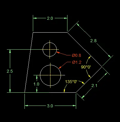
DECIMAL
AIM 2: To draw the given drawing in autocad.
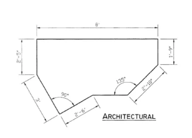
step-1
- select new drawing from ribbon.
- enter units and select ARCHITECTURAL and deciamal value in o.o
- enter pline and 1st point as 10,10
- after that @2'10"<45 angle enter
- after @1'9"<90
- enter @8'<180
- enter @2'5"<270
- enter @3'<315
- enter @2'6"<45
- close the line command with 1st point we took
step-2
- select the dimangle command enter and enter angle where we are to place
- select dimliner command mention the dimention where we are to place
RESULTS:
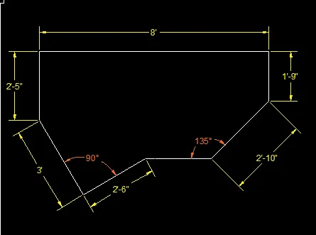
ARCHITECTURAL
AIM 3: To draw the given drawing in autocad.
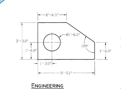
PROCEDURE:
STEP-1
- select new drawing from ribbon.
- enter units and select ENGINEERING and deciamal value in 0'0"
- Enter Pline command ente value 10,10.
- enter value @2'6.5" <180
- enter value @3'3"<270
- enter value @5'1"<0
- enter value @1'6"<90
- enter value draw line with angle of 125 degrees with anticlock-wise
- close line command with 1st poin we mention
step-2
- make the dimention with help of dim command
- mention the angles with help of dimang command
RESULTS:
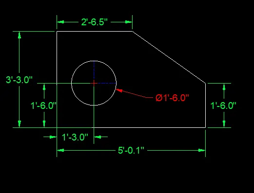
ENGINEERING
AIM 4: To draw the given drawing in autocad.
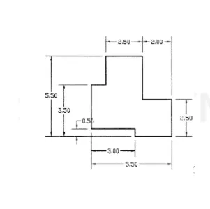
PROCEDURE:
SPEP-1
- select new drawing from ribbon.
- enter units and select DECIMAL and deciamal value in 0'0"
- Enter pline 10,10 enter
- next point @2.00<0
- next point @2.50<270
- next point @2.50<180
- next point @0.50<90
- next point @3.0<180
- next point @3.0<90
- next point @1.0<0
- next point @2.0<90
- next point @2.50<0
- joint the last point to 1st or close the command line "c" enter
step-2
- mention the dimentions with help of dim command .
RESULTS:
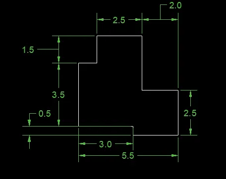
AIM 5: To draw the given drawing in autocad.
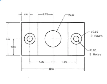
PROCEDURE:
STEP-1
- select new drawing from ribbon.
- enter units and select DECIMAL and deciamal value in 0'0"
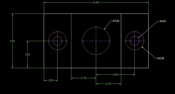
- Enter pline command select point as 10,10
- next point @11.50<0
- next point @6<90
- next point @11.50<180
- next point @6<270
- close the command .
step-2
- enter center line of drawings with help of osnap ON enter
- enter line command draw temparary lines verticaly dist of 1.5 and 7.00 enter
- enter circle command enter radius of 3 dia in middile point of center lines
- and after draw 2 circles in each point (11.5,13) and (20,13) with radius of 1dia and 2 dia
- remove the temperary center lines we made.
step-3
- with help of dim command mention dimentions required points
- with help of dimdia command mention dimeters of circles.
RESULTS:
AIM 6: To draw the given drawing in autocad.
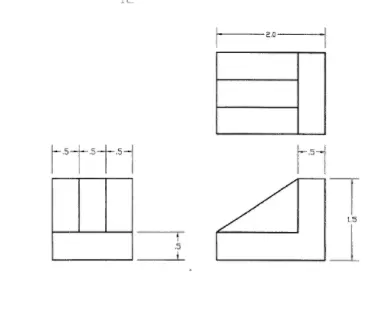
PROCEDURE:
step-1
- select new drawing from ribbon.
- enter units and select DECIMAL and deciamal value in 0'0"
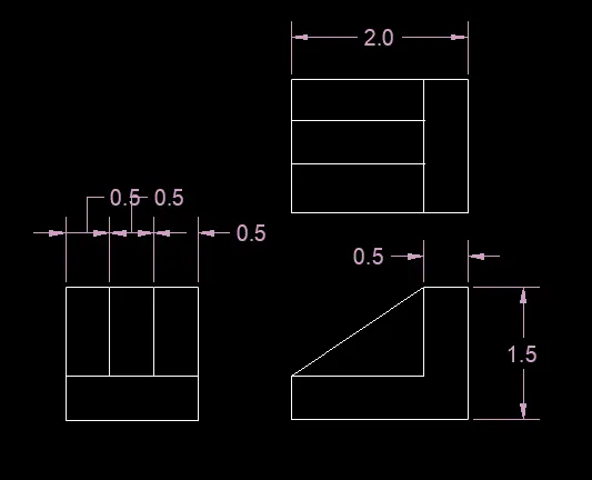
step-2 (front viewdrawing)
- enter command pline point 10,10
- next point @2.00<0 enter
- next point @1.5<90 enter
- next point @0.5<180 enter
- next point @1<270 enter
- next point @1.5<180 enter
- next pont @ 45 degrees line add to upper point 0.5 line end point before we made.
step-3(side view drawing)
- enter line command enter pont 0,10 enter
- next point @0.5<270
- next point @1.5<0
- next point @0.5<90
- next point @1.5<180
- next point @1<90 and offst this last object 2 times with distance of 0.5.
- finally draw a line 1st point (0,11.5 )to 2nd point (1.5,11.5 ) enter.
step-4 (top view of drawing)
- enter line command mention 1st point (10,12.5) enter
- nextr point @2<0
- next point @1.5<90
- next point @2<180
- next point @1.5<270
- draw vertical line offset of from right side 0.5 distance enter
- line command 1st point (10,13) next point @1.5<0 enter
- line command 1st point (10,13.5) enter @1.5<0 enter.
step-5
- with help of dim command mention dimentions required points
- with help of dimdia command mention dimeters of circles.
RESULTS:
AIM 7: To draw the given drawing in autocad.
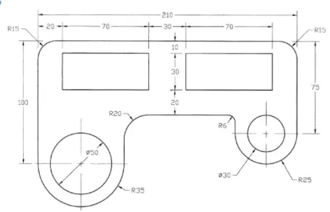
PROCEDURE:
step-1
- select new drawing from ribbon.
- enter units and select DECIMAL and deciamal value in 0'0"
STEP-2
- Enter line command 1st point is 10,10
- next point @210<0
- next point @75<270
- next point @50<180 (temparary line)
- draw circle with radius of 25 and draw circle of 30 dia with help of middle point of last line object
- remove upper part 25 radius circle with help of trim command
- again take line command go last point of temarary end point @15<90 enter
- next point @140<180 enter here before point made arc last the joint with radus 6 with help of fillet command
- next again take a line command continue the before where we stop @40<270 enter
- enter here before point made arc last the joint with radus 20 with help of fillet command
- next again take a line command continue the before where we stop
- next point @70<180 (temparary line)
- draw circle with radius of 35 and draw circle of 50 dia with help of middle point of last line object
- remove upper part 35radius circle with help of trim command
- next again take a line command continue the before where we stop @100<90.
- remove the temaparery line we made .
step-3
- with help of dim command mention dimentions required points
- with help of dimdia command mention dimeters of circles.
RESULTS:
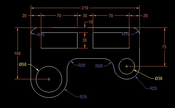
AIM 8: To draw the given drawing in autocad.
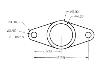
PROCEDURE:
step-1
- select new drawing from ribbon.
- enter units and select DECIMAL and deciamal value in 0'0"
STEP-2
- LINE Command 1st point 10,10
- next point @8.55<0 (temparary line)
- make 2 cicles in each points start point of a line with radious of 0.9 &0.9 dia
- after middile point of line with 5dia & 4dia
- and end point of line with radious of 0.9 &0.9 dia
- and draw a tangent line middile circle to both sides of circles top and bottom sides
- removw the temporary lines.
step-3
- with help of dim command mention dimentions required points
- with help of dimdia command mention dimeters of circles.
RESULTS:
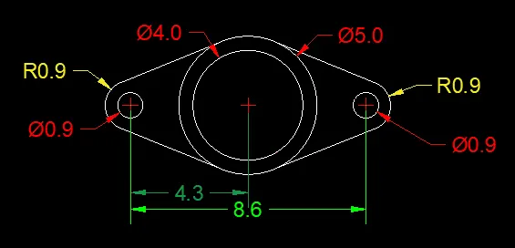
AIM 9: To draw the given drawing in autocad.

PROCEDURE:
step-1
- select new drawing from ribbon.
- enter units and select ENGINEERING and deciamal value in 0'0"
STEP-2
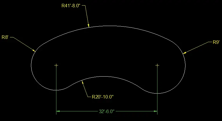
- LINE Command 1st point 10,10
- Next point @32'6"<0 (temparary line)
- make 2 cicles of both 1st point and end point line with a radious of 8' of left side and 9' of right side with help of circle command
- enter circle command after select option in circle 3P (tan tan radious) select tangent points upper points of both the circles before we made and radious of 41'8"
- remove the excess area of circle except that tangent points middile portion.
- enter circle command after select option in circle 3P (tan tan radious) select tangent points lower points of both the circles before we made and radious of 32'8"
- remove the excess area of cicle except that tangent points middile portion.
- remove the temporary lines with the help of erase command .
step-3
- with help of dim command mention dimentions required points
- with help of dimdia command mention dimeters of circles.
RESULTS:
AIM 7: To draw the given drawing in autocad.
PROCEDURE:
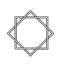
step-1
- select new drawing from ribbon.
- enter units and select ENGINEERING and deciamal value in 0'0"
STEP-2
- LINE Command 1st point 10,10
- select rec command draw rectangle with dimention of 5,5 enter
- draw a another rectangle with 45 degrees angle with referance point center point of rectngle 1st we made
- after that use offset command offset the both the rectangles with distance of 1 .
- remove the overlaping lines in joints with the help of trim command
step-3
- DIMENTIONS ARE NOT REQUIRED.
RESULTS:

AIM 8: To draw the given drawing in autocad.
PROCEDURE:
step-1
- select new drawing from ribbon.
- enter units and select ENGINEERING and deciamal value in 0'0"
STEP-2
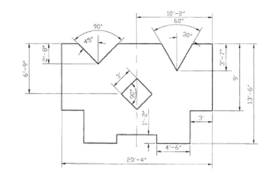
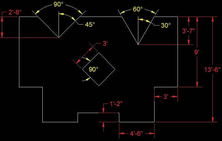
- LINE Command 1st point 10,10
- NEXT point @20'4"<0 after 9'<270 after @3'<180 after @4'6"<270 after @4'6"<180 after @1'5"<90 after @5'4"<180 after @1'2"<270 after @4'6"<180 after @4'6"<90 after @3'<180 after close the line command.
step-3(v shapes)
- draw left line offset the 2'6.5" and take a downward offset point 2'6" there onwards draw a 45 degrees middile v shape lines to be draw.
- draw left line offset the 2'6.5" and take a downward offset point 3'7" there onwards draw a 30 degrees middile v shape lines to be draw.
step-4 (middile square)
- select sa center line over all rectngle draw a square with angle of 90 degrees sides of 3'.
step-3
- with help of dim command mention dimentions required points
- with help of dimdia command mention dimeters of circles.
- with help of dimang command mention angles of circles.
RESULTS:
COMMANDS USED IN THIUS DRAWINGS:
- L - LINE
- C- CIRCLE
- O- OFFSET
- RO - ROTATE
- DIMLIN - LINEAR DIMENTIONS
- DIMANG-ANGELER DIMENTION
- DIMDIA- DIAMETER
- FILLET- FILLET
- TR- TRIM
- EX-EXTEND
- E-ERASE