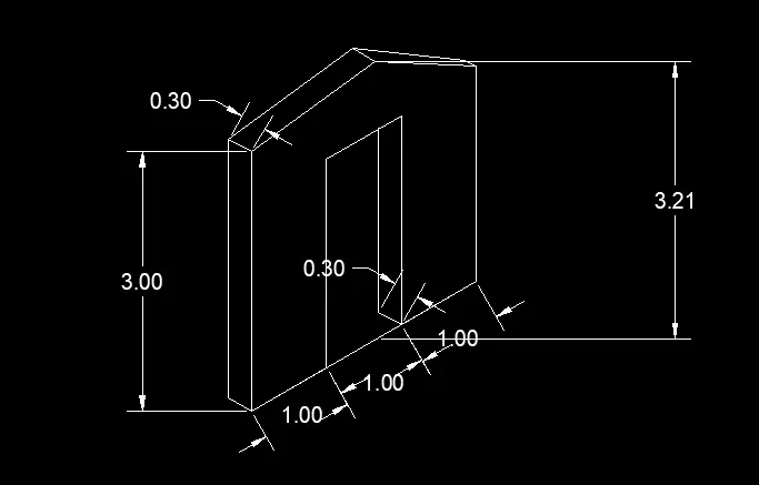
Creating a Floor plan, Footing detail and Isometric view using AutoCad
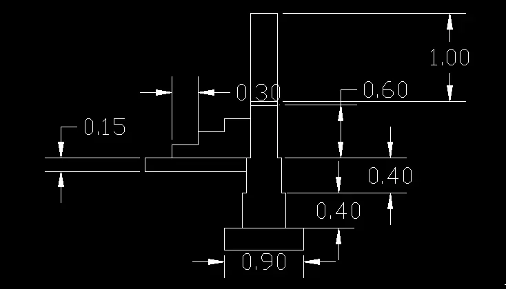
1.useing commands : line , rec
command : rec 0.90,0.25
make a rectangle value of : 0.90,0.25
make anotherone plae on the before one:0.40,0.50
make anotherone plae on the before one:0.40,0.40
make anotherone plae on the before one:0.60,1.6
make a plane object beside of 0.60,1.6 object :0.15,1.15
afet that make a steps on plane of 0.15,1.15 :
rise :0.15
tread:0.30
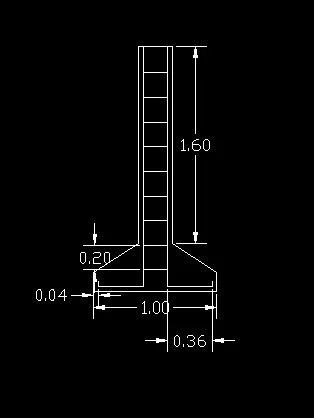
2.useing commands :line
command : line
second poin : 1.00 enter
next point :<90,0.15
next point :<45,0.20
next point: <90,1.60
next point: <180,1.08
next point :<270,1.60
next point:<225,0.20
next point : <270,0.15 close the object.
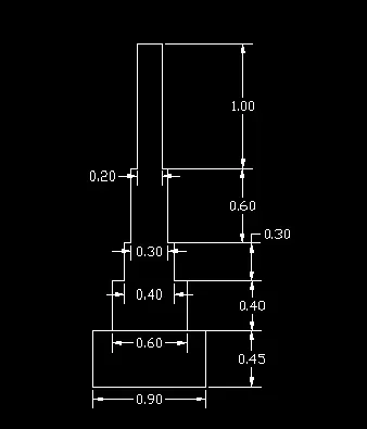
3.useing command : line
command :line

command : line enter
enter 1st point: enter
enter 2nd point : value 0.90 enter ( in this caase maintain "osnap" & "ortho"should be on)
enter next point: @0.25<90 ( "<" this symbols includes the angle of line in which direction)
enter next point: @0.90<180
enter next point: @0.25<270
place rectangle : 0.4 &0.4
next rec enter : 0.3&0.3
next object is : 0.20&1.6
commands :line, isomatric draft
command : line
this drawing made in isomatric draft drawing.
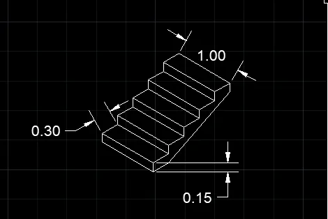
commands useing: isomatric draft ,line
this drawing made in isomatric draft drawing.