Creating a Residence Layout, Seating plan, Toilet and Utility room plan using AutoCad
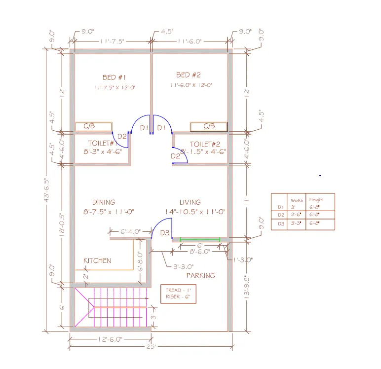
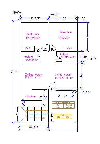
AIM: To draw the given drawing residential plan in a autocad software.
PROCEDURE:
Step-1:
- select new drawing from ribbon.
- enter units and select ENGINEERING and deciamal value in 0'0"
- take xline command and draw vertical and horizontal lines in 1,1 point
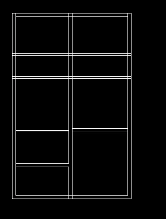
- with useing offset command draw a 9" dimenssional lines besides a xlines vertical and horizontal.
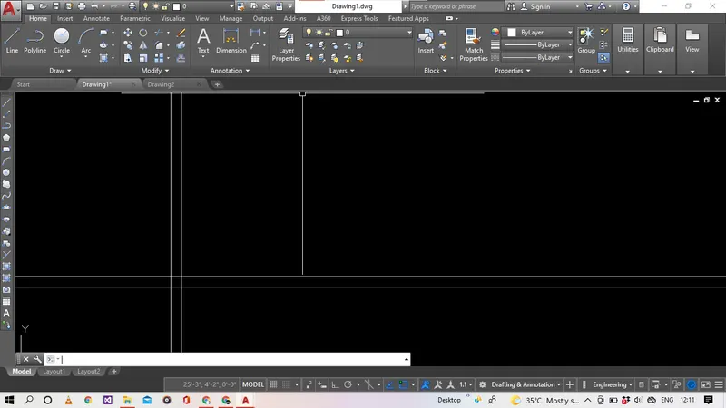
- with erase , trim command remove unwanted lines.and also separate colidal lines into stright and clear.
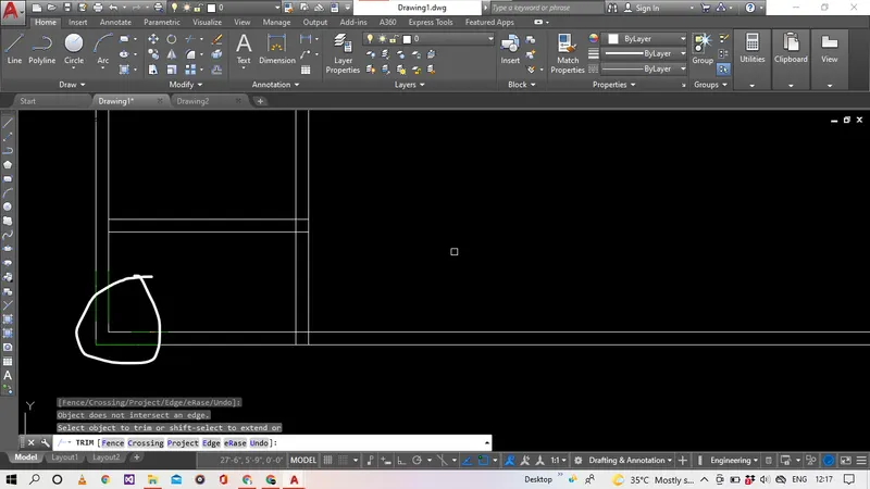
- after that 6' dimentional vertical line draw the offse of primary horizontal line.
- after that another offset of4.5" inch of horizntal line draw to add a interna wall thickness. clear the unwanted lines.
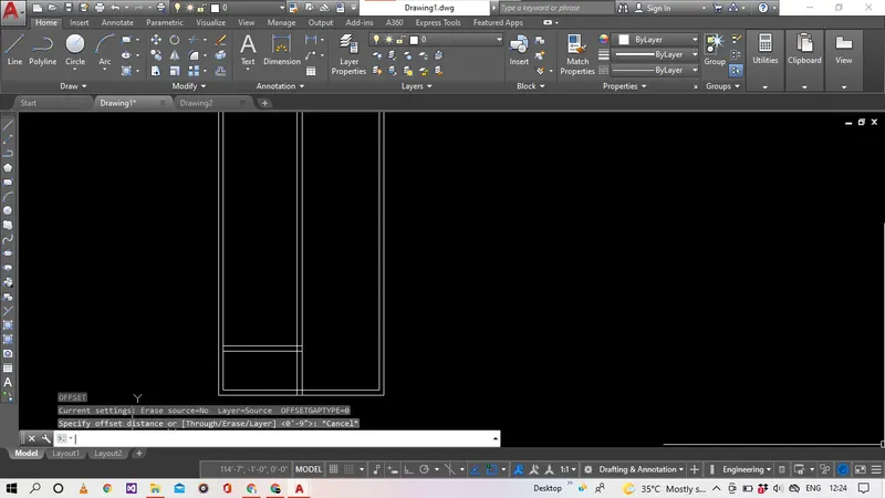
- after that add the offset of vertical lines to be added 12'6" another 8'6" vertical.
- after that add the 11' ,4'6" and 12' horizontal lines will be added by the help of offset command and aso add the the wall thickness every line
- after this room seperation will be completed.
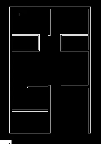
- with help of trim and fillet command remove the jountion merged points in to seperte
- as relatively addjust the room sizes and also mention the doors.
- in point of door placement draw small 2inch line both the sides to help a circle to place with 2 tangent points method.

- with help these 2 points draw a circle, 1 point as a center of circle and another one as a end of the circle radious
-
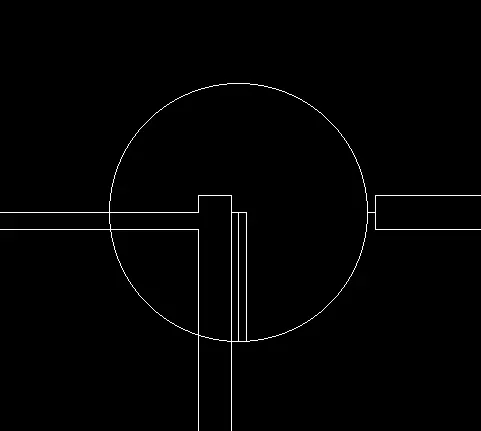
- erase the un wanted lines with help of trim option.
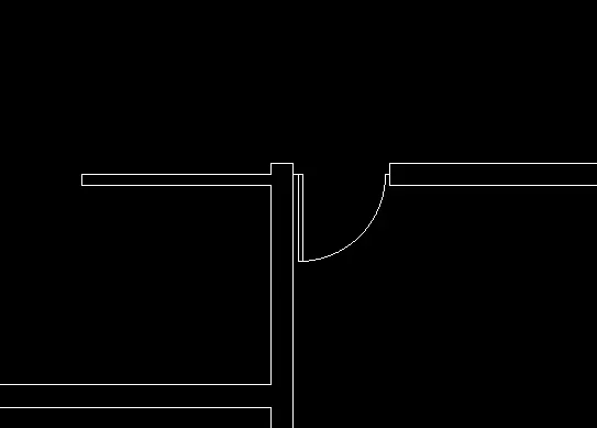
- same process will follow the all door formets.
- door sizes divided into 3 types
S.NO. length height D1 3' 6'8" D2 2'6" 6'8" D3 3'3" 6'8" 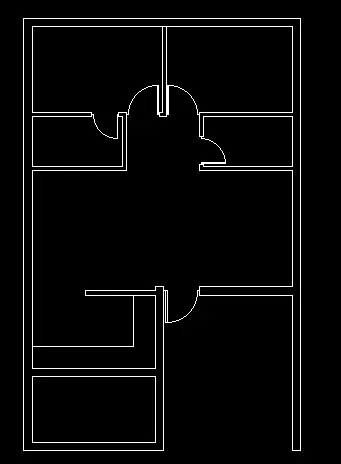
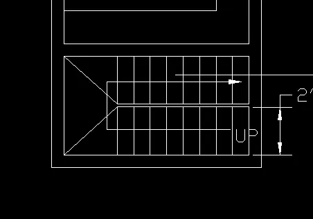
- stair case farmet is doglegged design with of offset command in mention place.
- staires are calculated by height of the slab.
- in residential slab height 3.15 m will be provided
- if rise is 6 inches provided as per calcullated the height. legnth of stair is 3' and tread of a stair is 1'.
- widow cotting made the offset command
step-2
- make the dimention with help of dim command
- mention the angles with help of dimang command
RESULTS:
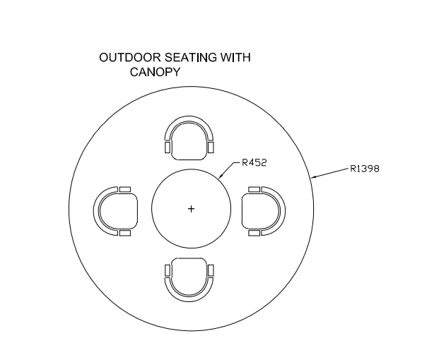
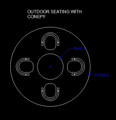
AIM-2 :To draw the given outdoor canopy in a autocad software.
PROCEDURE:
Step-1:
- select new drawing from ribbon.
- enter units and select ENGINEERING and deciamal value in 0'0"
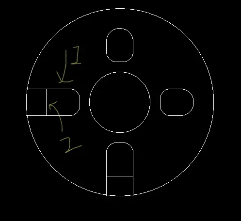
- with help of c command draw a circle with radious of 1398
- after that draw the another circle with radious of 452 exactly in center of primary circle.
- after that draw a vertical and horizontal center Xlines. after that offset thsat lines with 200mm distance.
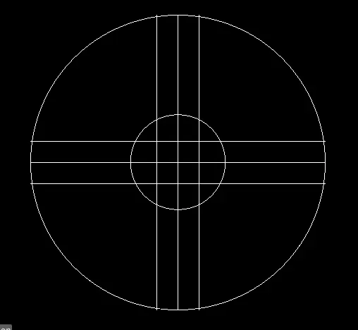
- draw a tangents four sides of middile circle. after that offset that tangent lines into 150mm.
-
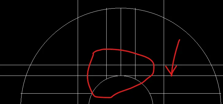
- attached circle tangent lines will be erased with help erase option.
- with the help of fillet option tangent lines makes a radius of 150mm.
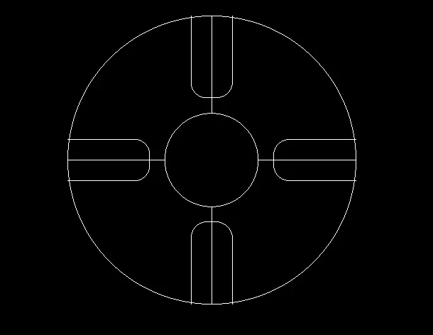
- remove the middile lines with the help of erase command.after that offset that the marked lines with the 500mm distance.
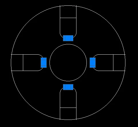
- trim the extrta lines in the drawing that offset lines perpendiculer lines will be curved in with help of fillet command.
- fillet enter > radious enter < radious dixtance 200mm enter < select 1st point < select 2nd point enter.
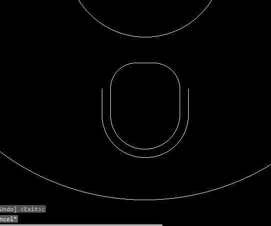
- offset the 3 sides of semi-circuler shaped object with 50mm distance.
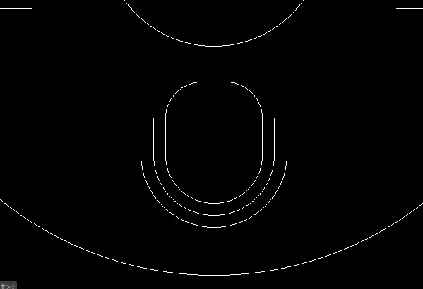
- again offset that lines with distance of 50mm
- close that befored offseted lines and offset that lines with 100mm distance and 20mm distance to seperate the lines like mention below.
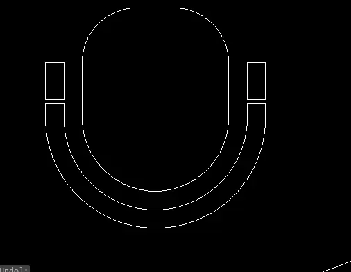
- this process will be contineoued in four sides.
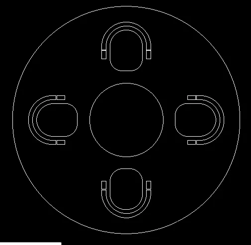
step-2
- make the dimention with help of dim command
- mention the angles with help of dimang command
- text made with the commnad of mtext.
RESULTS:
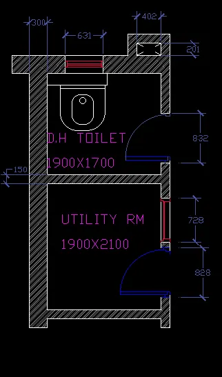
AIM:TO . Sketch the part plan for the toilers and utilities room. Consider the outer wall thickness as 300mm and inner wall thickness as 150mm. Also, assume the missing dimension, Texts, dimensions, and hatches are only for references. Also, symbols for toilets and w/c are also for references.
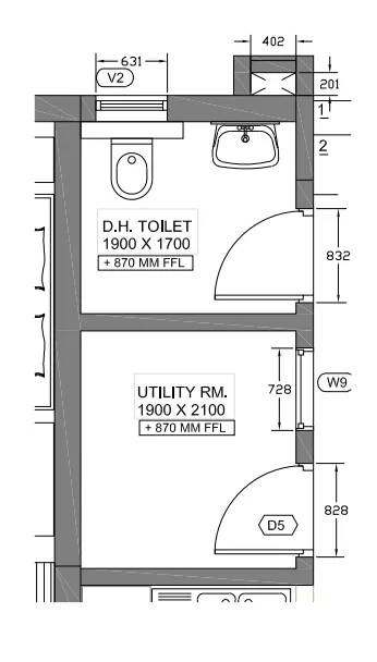
PROCEDURE:
Step-1:
- select new drawing from ribbon.
- enter units and select ENGINEERING and deciamal value in 0'0"
step-2
- draw the xlines (constraction lines) with command in both directions
- off set the vertical line with 300mm distance
- offset the horizontal line with 150mm distance.
- remove the unwanted lines with help of trim command
- after that offset the horizontal lines with distance of 2100mm<150mm<1700mm<300mm.
- vertcal offset into 1900mm distance.
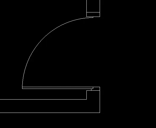
- now draw the lines for door cutting 100mm offset the horizontal base line after that again offset the one 828 and 832 given placesbe side of horizontal lines.
- offset lines will be pointed in below immage.
-
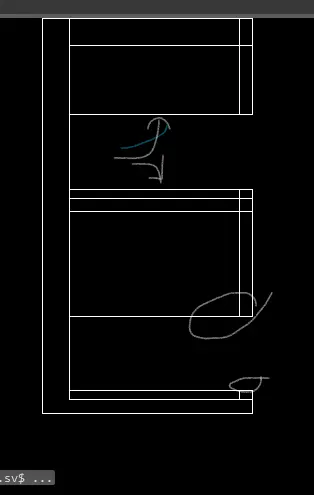
- now draw 10mm lines both wall hinges place after that that points will connected draw circle one point as acenter point of circler another end tangent point.
- after unwanted lines will trimmed with help of trim command.
- same procedure for a window cutting
- hatching is added in the walls with the help of hatch command
- hatch < select prefered point < size of hatching material enter.
step-2
- make the dimention with help of dimLin command
- mention the angles with help of dimang command
- text made with the commnad of mtext.
RESULTS:
COMMANDS USED IN THIUS DRAWINGS:
- L - LINE
- C- CIRCLE
- O- OFFSET
- RO - ROTATE
- DIMLIN - LINEAR DIMENTIONS
- DIMANG-ANGELER DIMENTION
- DIMDIA- DIAMETER
- FILLET- FILLET
- TR- TRIM
- EX-EXTEND
- E-ERASE
- h-hatch
- xl- constraction line