Project 2_Creating a 3D rendered model for a Residential Building in AutoCad
AIM :-
To create a 3d model of the residential building with a rendered view.
INTRODUCTION :-
To create the 3d model of residential building we are using Autocad software with the following commands :-
1.UN
2.LIMMAX
3.ZOOM
4.LAYER
5.EXTRUDE
6.RECTANGLE
7.COPY
8.MOVE
9.CIRCLE
10.CAMERA
11.RENDER
12.LINES
13.TRIM
14.MTEXT
15.TEXTEDIT
16.LIGHTS
17.OFFSET
18.BOUNDARY
19.SUBTRACT
20.MAT
21.XLINE
PROCEDURE :-
First step involves open AutoCAD and switch the view from drafting and annotation to 3D modelling
Type UN to change the units to decimal and millimetres
Type limmax and set the maximum size of the working area
Type zoom and all
Now create layers using the layer tool as per the requirements
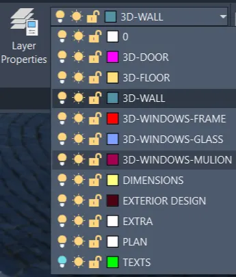
Then to create a plan of a three floor residential building
First use the X line tool to draw the horizontal and vertical lines
Then trim the unwanted lines
Offset 230 mm both vertical and horizontal lines
Then draw offset of 5000 from horizontal and 5000 from vertical to draw the bedroom and then again offset it 230 mm horizontally and vertically.
To draw the kitchen and dining draw and offset of 5000 from the 230mm offset wall and offset 3500 from horizontal line to draw the boundary. Again offset it 230 mm.
Trim the unwanted lines and draw door of size 1000 mm
Do the same procedure to draw staircase, study and office, drawing room, wc and wash basin as the required dimensions.
To write the text, use the mtext tool with height 100.
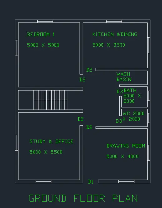
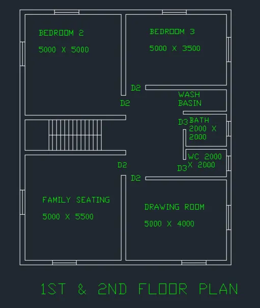
Copy the plan to draw the second and third floor and make the changes as per the requirement
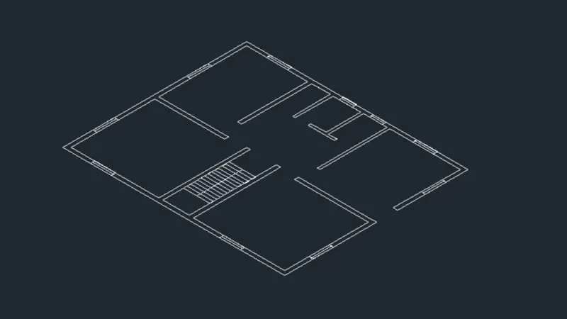
Change the view to the 3D view by clicking on the home button available on the navigation bar.
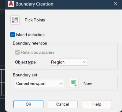
Now to create the boundaries of each object drawn type b o and then select pick point to create the boundaries
Select every single drawn object and then make them boundaries or region
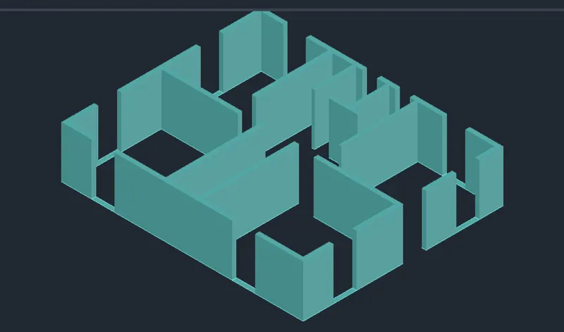
After doing so now select the created regions and then select the extrude tool from the toolbar to extrude them to the height of 2.5 m
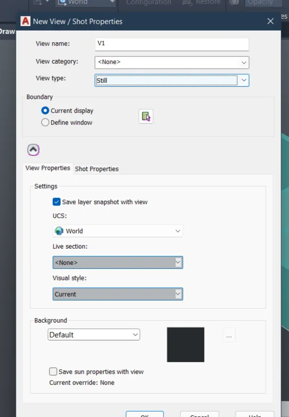
After that to create a new view click on the view and then make a new view by clicking on ok and name it as V1.
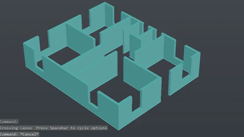
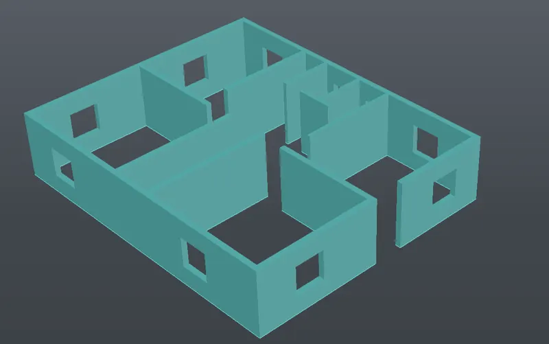
After that create rectangles on the boundary of window and make them boundaries by typing the B0 command
Then select the extrude tool and extrud them to a height of 750 mm from the ground
Then change the ucs by typing the ucs command and selecting the face option and select the top face of the created walls and click ok
Then draw rectangles on the top of the walls where the windows are attached and make them region by typing the boundary command
After that extrude them by -750 mm
To create the windows
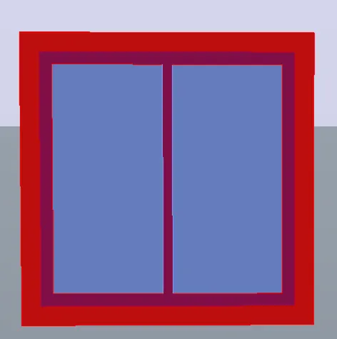
First select the layer Windows frame and then draw a rectangle of dimension 1200 X 1200
Offset the created rectangle by 100 mm and then again of set it by 20 mm
Draw Centre line from the bigger rectangle and then trim the unwanted lines to create a frame, mulion and glass.
Select them and make the region by bo command
After that select the bigger rectangle and then select the inner one and use the command subtract to subtract it
Same step follows for the glass, select the union part and then select the glass part and subtract them.
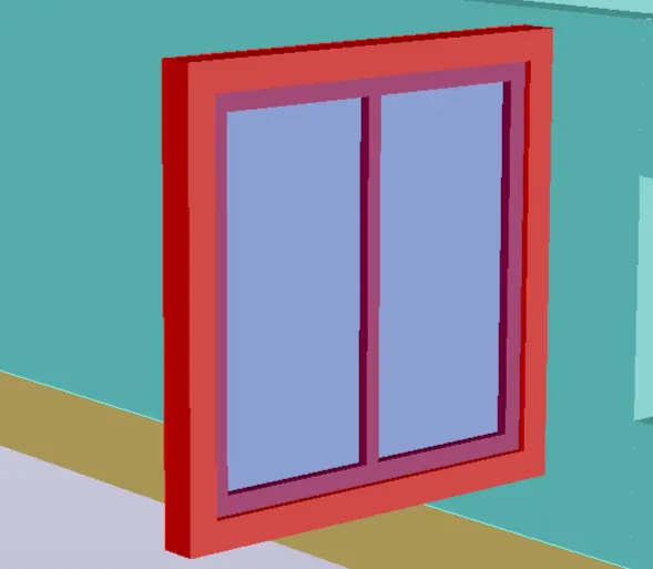
Now the created window is to be extruded using the extrude command
Extrude the frame 100 mm
Then select the mulion and extruded 80 mm
Then select glass and extrude it 50 mm.
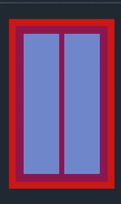
To create the windows of the washroom and wash basin
Change the ucs to ucs face and select the Washbasin wall face
Draw rectangle of dimension of 750 X 1200
Now offset rectangle 100 mm and again offset the offsetted rectangle 50 mm.
Further steps are same as the normal windows created.
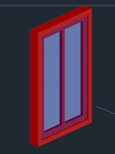
Place the window by copy and moving it to the desired place
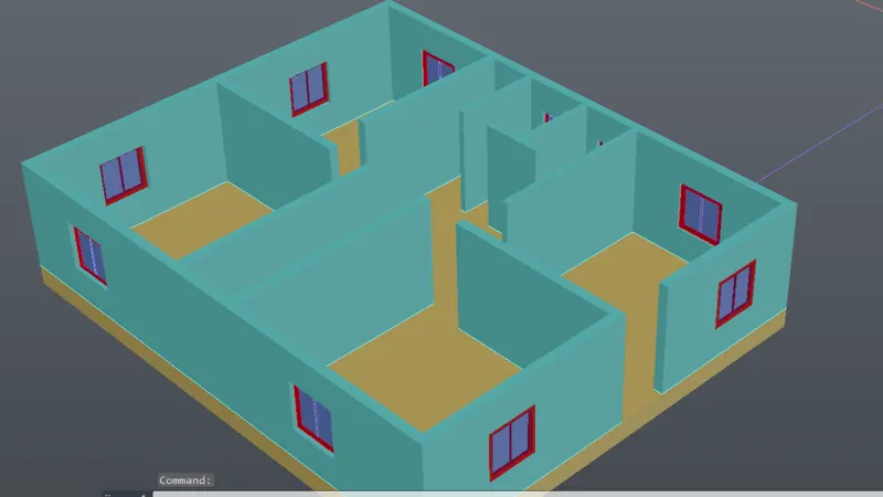
Now to create a roof draw a rectangle by selecting the ucs to the face option and clicking it to the top face and then draw rectangle from the inner edges of the wall
Make it region by typing the boundary command and then extrude it by 500 mm
To create designs draw a rectangle of any dimension on the front face by selectung the ucs on front face and make it region by bo command and extrude is 100mm
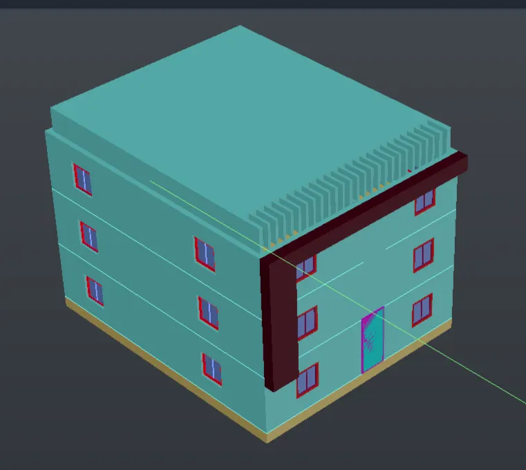
To fix the camera first draw a circle of any dimension and extrude it to a point of any height and then select the camera option and fix a camera
Give the desired settings as per the requirement and then press it ok
The attached view is from the camera view
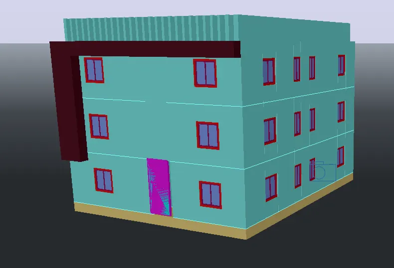
Then select the sunlight status on and click on the adjust settings then a dialogue box opens
Turn on the environment and then click ok
Use the MAT command to add Different designs to the created building
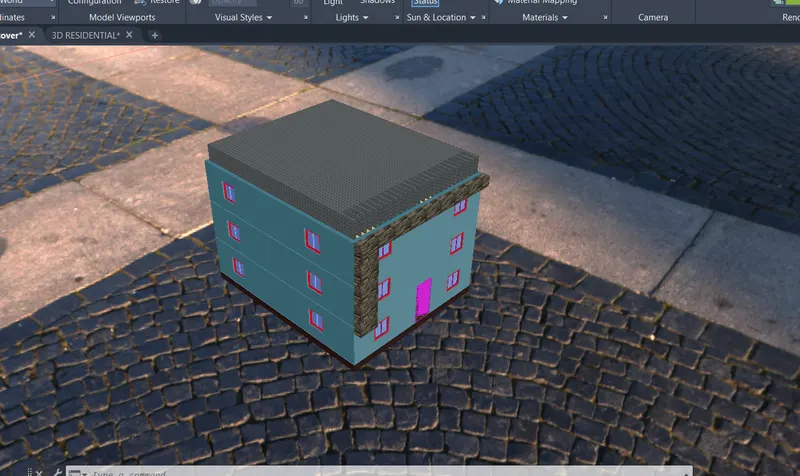
Select the render tool from the toolbar and then render it with the desired settings and click ok to save after rendering.
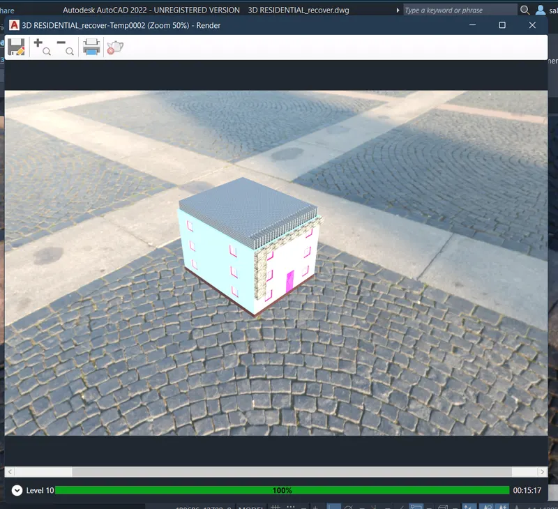
RESULT :-
Created rendered building is attached below :-