Project 2_Creating a 3D rendered model for a Residential Building in AutoCad
AIM
To create a Plan, Elevation, Isometric view and 3D Render view using the various commands in Auto CAD.
INTRODUCTION BY 3D VIEW
- The process of creating a mathematical representation of any surface of an object in three dimensions by using special software.
- A 3D model can even be represented as a two dimensional image by using the 3D rendering process.
- It enables the professional creation and edition of 2D geometry and 3D models with solids, surfaces and objects.
PROCEDURE
- To create a new sheet from application of Auto CAD.
- Go to the setting and to change the view of the page from Drafting to 3D modeling.
- Type ,,UN’ to set the units of current format of measure.( feet and inches).
- Type ,,LIMITS’ to set the maximum dimension limits on the particular page.
- First we take the top view of the page.
- To create a plan and elevation at 2D.
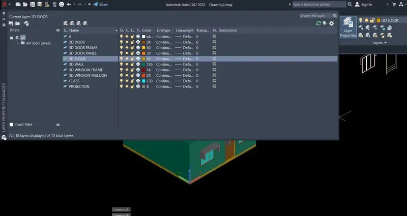
- Then, to assign the various layer properties of all objects like wall, door, window, floor, text, furnitures, frames, panel,etc’’, with a required colour.
- Type ,, BOUNDARY’ to create a plan to region or polylines from enclosed lines.
- Type ,, OPTION’ to change screen color to BLACK.
- Command, SHADE ‘ to want modify the border of the wall to visibility.
- Type ,, LAYERISO’ to create the separate path of line with a shaded view that remains the visible and unlocked are termed isolate.
- Then , to take command,, EXTRUDE’ extrude to create a surface or solid of a 2D surface.
- Here, we take the extruded height of wall is 10 feet.
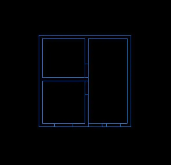
- Total plan dimension is 20’ x 20’.
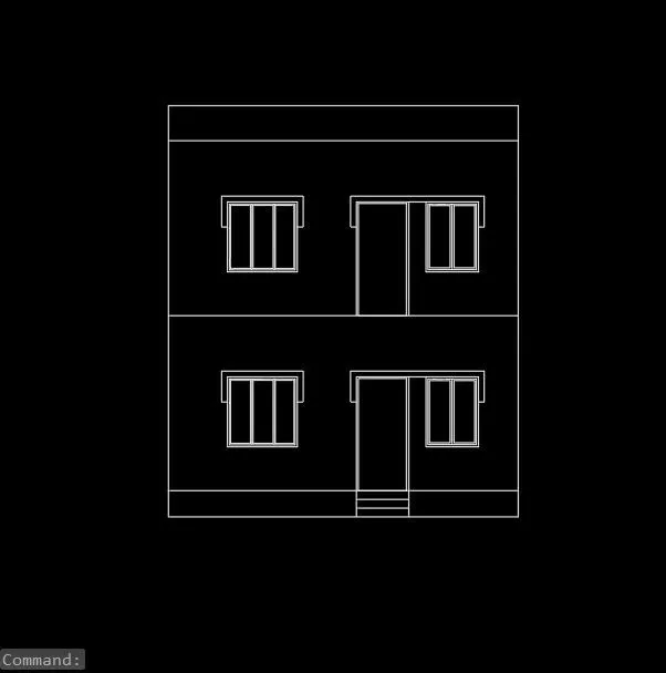
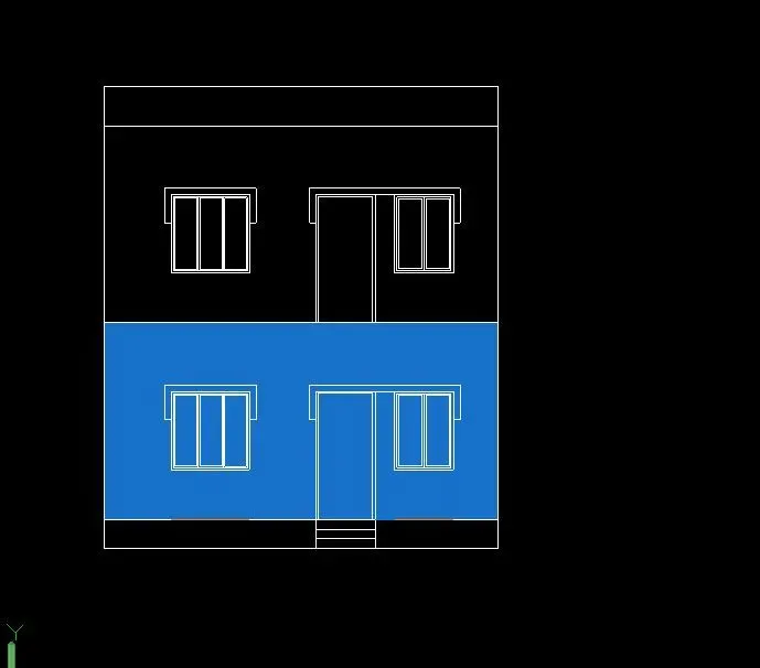
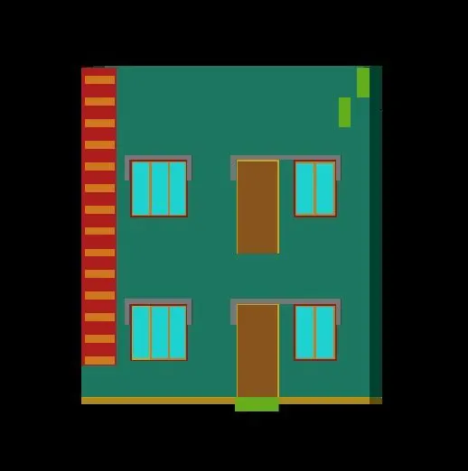
- Elevation is designed by G+1 floor.
- Type ,, REC’ to create a rectangle with a given dimensions.
- For here to fix the window before we create the rectangle at bottom of wall and then we extrude the rectangle area.
- Type ,, subtract ‘ to delete the window area for open view.
- The window dimensions of W1 = 3’ X 4’ and W2 = 4’ x 4’.
- Type ,, UCS’ to set the origin an orientation of the current user coordinate system, its establishes the XY work plane , horizontal and vertical direction, axes of rotation and other useful geometric references.
- Type ,, UNION ‘ to used combine the selected 2D regions or 3D solids by the addition. This to convert the one or more parts to the single region.
- To check the elevation visibility with the reference of plan.
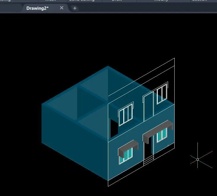
- Then, to merge or add the perfect view of elevation with 3D shaded isometric view.
- After, comes to follow the boundary and region of all parts like frames, panel view with the proper SUBTRACT of the objects.
- Continuously , to create the door and window setup by projection of extrude the objects.
- The main area of plinth area to created with the thickness of 6 inch.
- To create the REC at roof slab with the thickness is 5 inches.
- EXTRUDE’ extrude to create a surface or solid of a 2D surface.
- After that, copy the all objects to make the second floor of same properties.
- After covering the rood slab of first floor, kept to convert the parapet wall of the terrace.
- The parapet wall thickness is 4.5” and height of the wall is 3’.
- Type,, SOLIDEDIT’ to select face, follow to create the projection of any elevation purpose.
- To create a staircase of entrance of the home with the dimensions of Tread is 3 feet and Riser is 6 inches.
- Then, to create the Balcony at the first floor with the area of 9 feet x feet.
- The covered wall thickness is 4.5 inches and height of the wall is 2 feet 6 inches.
- After the important role of create a floor around surround area of building to make the better aesthetic view of the diagram.
- Type ,, 3D ORBIT’ to view a 3D orbit viewport in the current viewport.
- To change the parallel view of diagram.
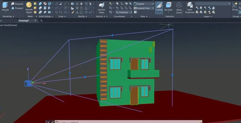
- Create ,, CAMERA’ for used to view of target location and to save a 3D perspective view of the objects.
- To set the proper location, direction of view and height.
- To take a better options of LIGHTS , for three types of light is there like spotlight, point and distance.
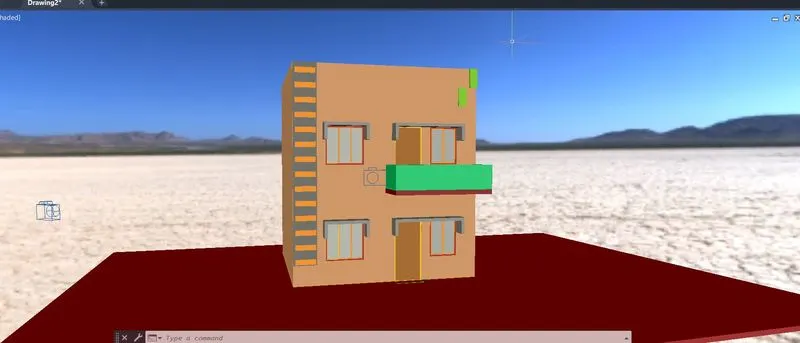
- To change the option of sky background is ON.
- The most important of 3D elevation view is material browser.
- The Material Browser is used to allows the all things of elevation like wall paint, ceramics, tiles, wood, etc..,
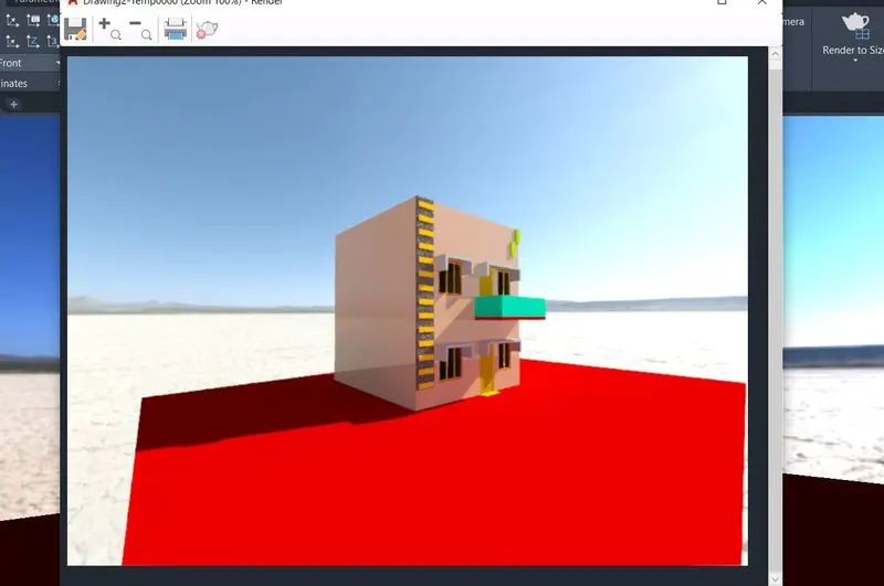
- Type,, RR’ to render the images by creating the view of rectangle. If we not specified the view, here automatically render the current view.
- To save the diagram to particular file.
RESULTS
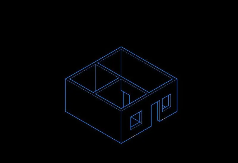
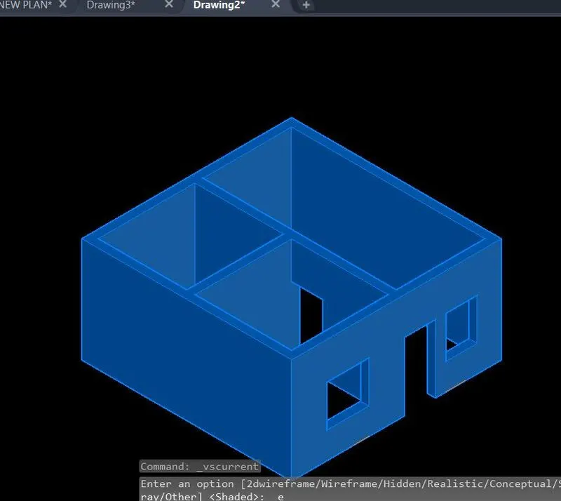
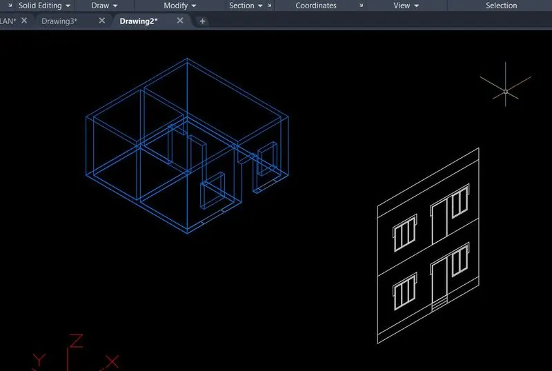
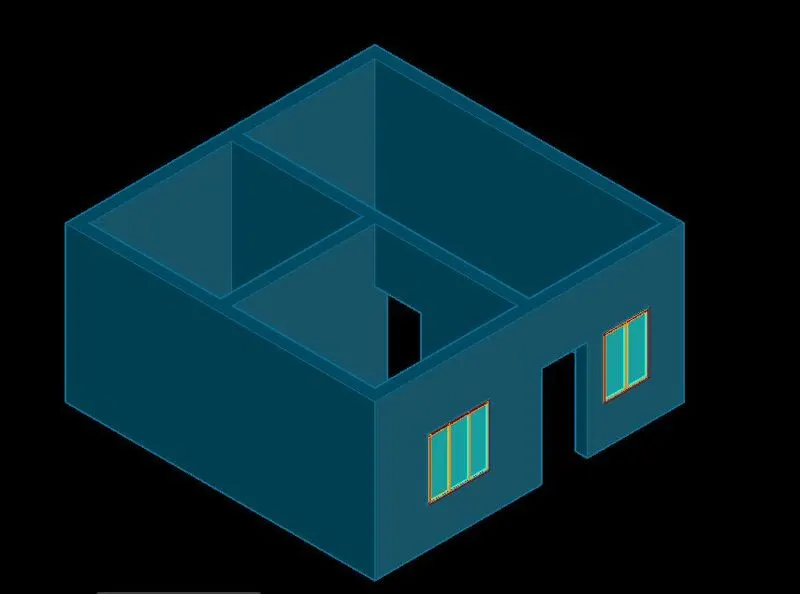
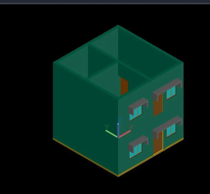
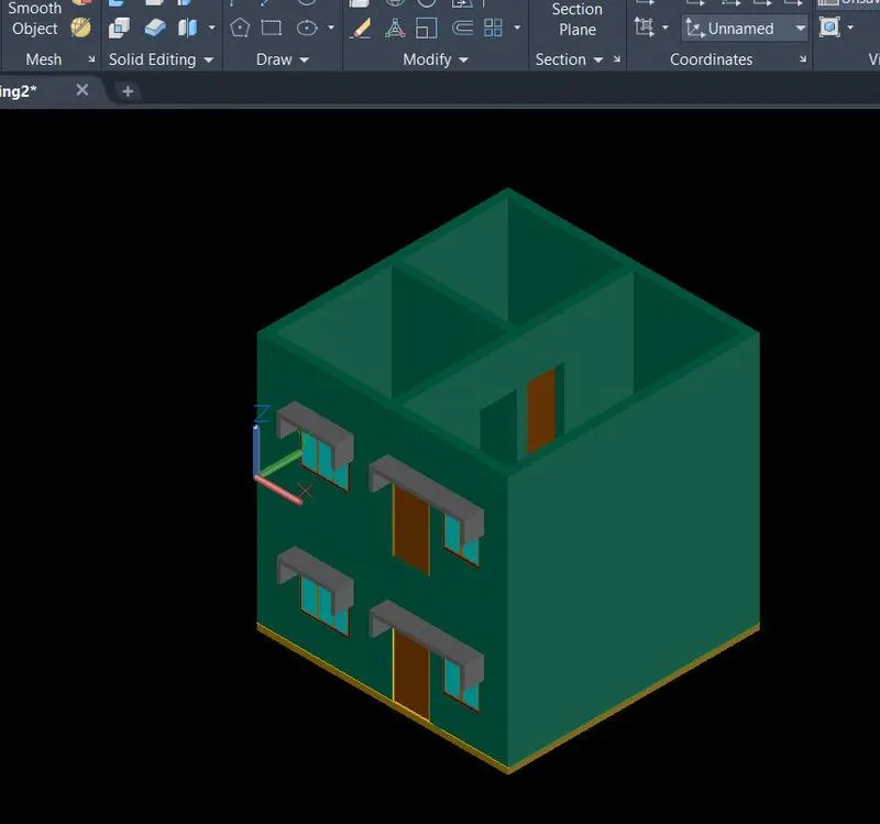
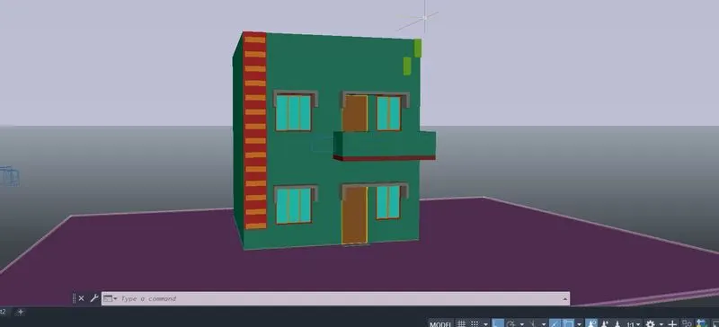
The diagram of Plan, Elevation, 3D isometric view and render view is drawn as per dimensions using the software of Auto.
DIAGRAM