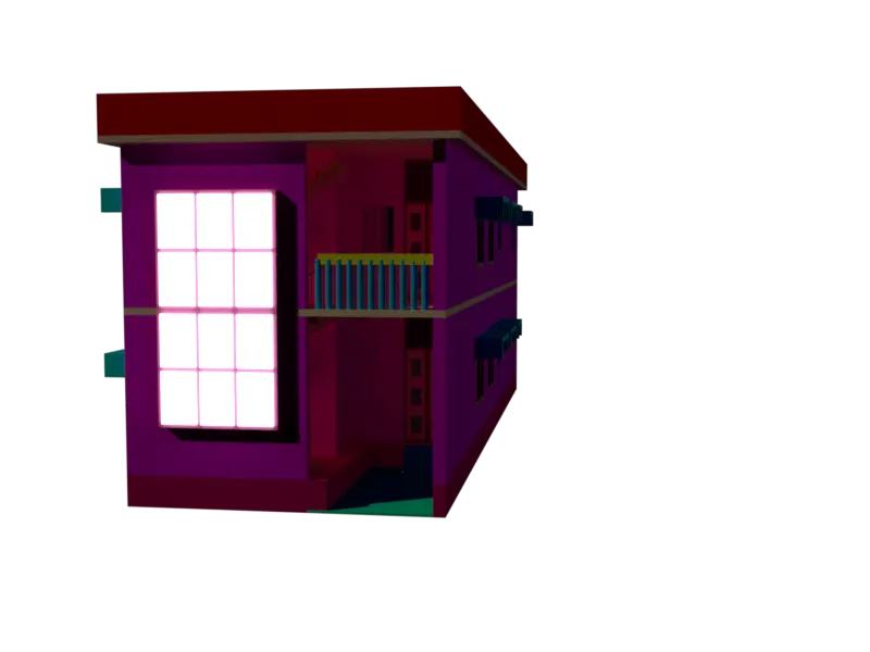
Project 2_Creating a 3D rendered model for a Residential Building in AutoCad
Project 2-Creating a 3D rendered model for a Residential Building in AutoCad
Jagadeep.M.M
AIM:
Create a 3D residential Building & rendered model in Autocad.
PROCEDURE:
- Open autocad softwere, type QNew incommand box,press enter.
- Select default setting as imperial setting.
- Drawing units setting as length=(Engineering),precision=0'0.0", Ok
- Drawing limits setting as, specify the lower left corner=enter,upper right corner=100',100',enter.
- Type the command box Dimension style manager & press enter.
- enter modify-enter primary units-unit format=Engineering, precision=0'0.0",enter Ok.
- Give the size of the plot using the rectangle command & offset for the thickness of the wall.
- Give the orientation of the plot by making the east direction.
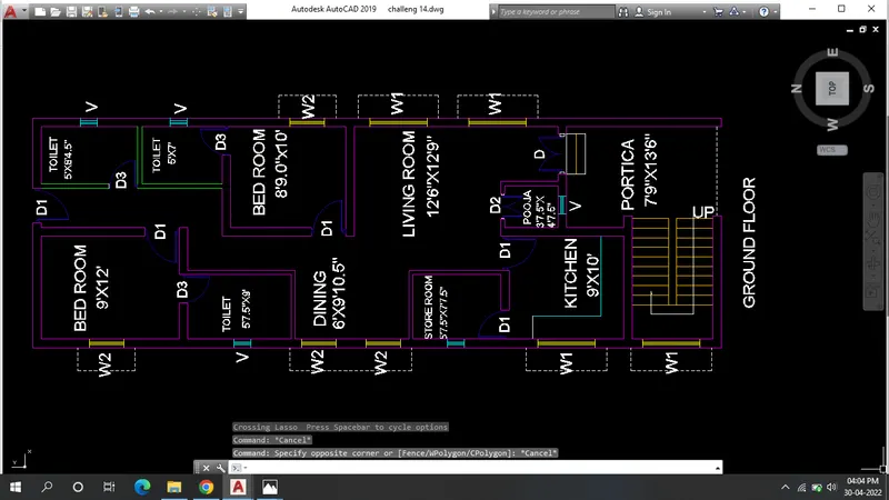
- Now we draw the groung floor:
- First we plot the size of the drawing 60'X20'.
- give the inside offset as 9" of the wall thickness.
- use the offset command draw the bed room of the size 9'X12'.
- give the outside offse of 9" wall.
- give the offset of below the horizontal direction 5'7.5"X9' attached toilet in above the bed room.
- give the offset of 3'4.5" in right direction.
- give the offset of 4.5" in vrtical direction & draw the toilet of the size 5'X8'4.5".
- give the offset of 4.5" below & again give the offset of 5'X7' of the toilet.
- give the offse of 9" below & give the offset of horizontal & vertival direction of the bed room size 8'9"X10'.
- now give the offset of 4'9" is the living room & dining hall are below the bed room & again give the offset of 4.5" in left side.
- To draw the store room of the size 5'7.5"X7'7.5" ok
- To draw the kitchen 9'X10' & give the thickness of the wall 9" enter.
- Draw the pooja in right side give the offse of 3'7.5"X4'7.5" enter give the wall thickness as 4.5".
- Now draw the stair case the dimension of the size is 10'9"X7'.
- Stair dimension thtead-10" , rise-6" & width is 3'2" ,number of steps-19.
- give the landing is 3'.
- give the portico dimension of right side 7'9"X13'6" enter.
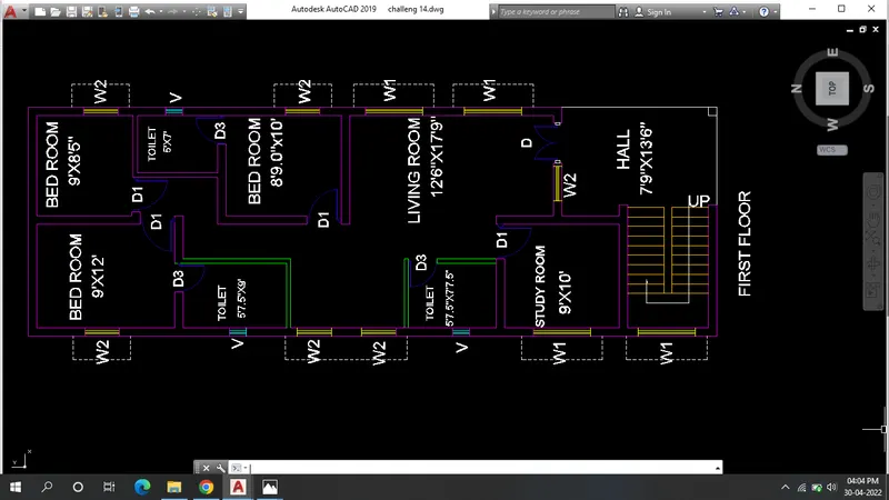
- Now we draw the first floor:
- copy the ground floor plan & we make few changes.
- The kitchen is replaced with the study room & dimension will be same.
- The pooja room will be removed in this place.
- NW toilet will be changed bed room size of 9'X12'
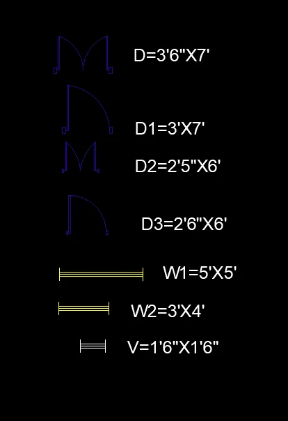
- Now we create the door & windows & make the blocks.
- Assume the door size as D=3'6"X7'(double door), D1=3'X7', D2=2'5"X6'(double door),D3=2'5"X6'.
- Assume the window size as W1=3'X5', W2=5'X5', V=1'6"X1'6".
- Now insert the dimension using dimension command.
- insert the text using text command.
- give the layer using layer commad.
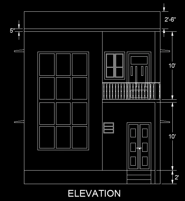
Elevation
- Now project the lines to draw the elecation.
- Project the wall lines to the top & draw the vertical lines.
- offset 2' for the plinth level & 10' for the ground floor & 5" for the slab thickness & 10' for the first floor.
- We draw the door,windows & ventilator & give the height of 7',4'& 1'6" as required.
- Trim the unwanted line using trim command.
- create the top of the parapet wall.
Constructing the 3D model:
- Create the layer using layer command.
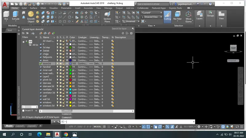
- Click on the workspace switching select the 3D modeling.
- Click the 3D view.
- Create the region & boundry.
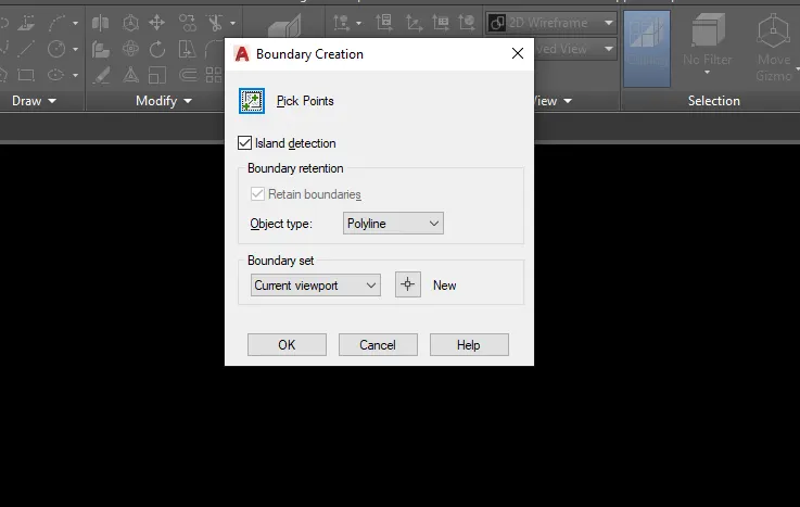
- create the plinth (create the rectangle) & extrude it the 2'.
- Create the front steps.
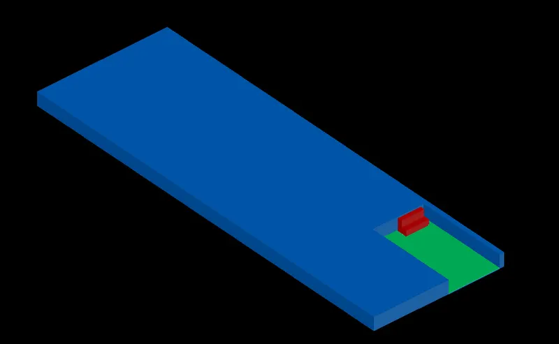
- Use the extrude command & extrude the out side wall height of 10'(Ground floor & First floor).
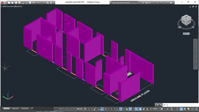
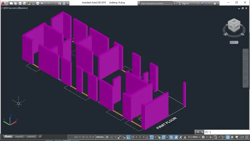
- create the internal wall extrude at 7'
- Layoff the external wall.
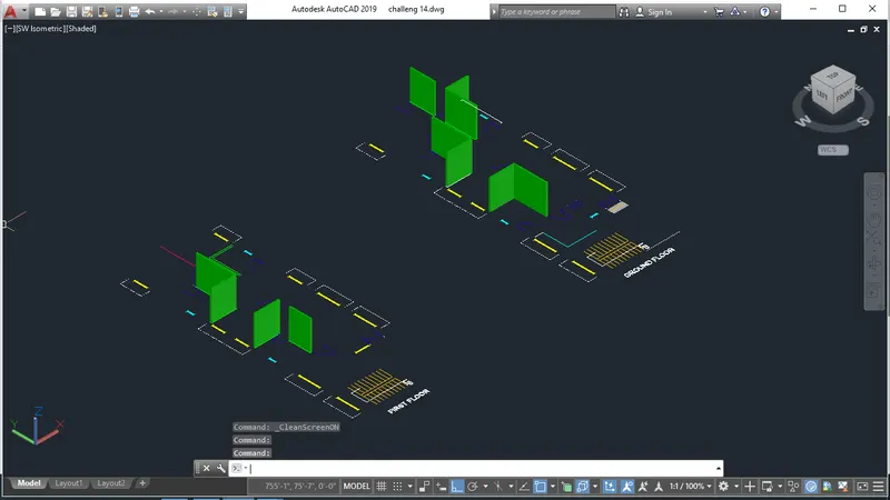
- Give the opening of Doors , Windows & Ventilation.
- Create the rectangle & extrude it where the Door,Windows & Ventilation required.
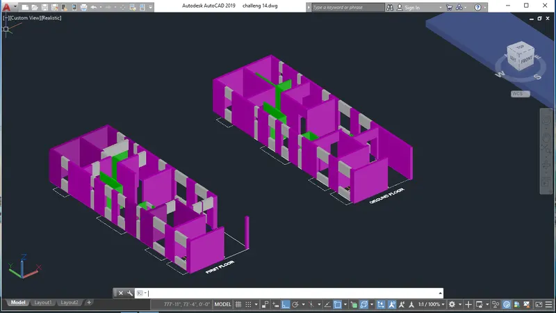
- Use the Union command select the object & merge it.
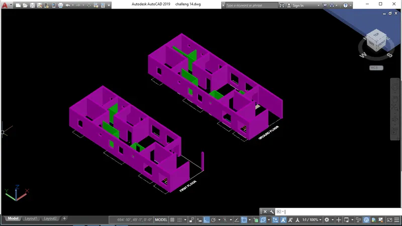
- Create the door,window & ventilation required dimensions.
- add the matrials & colors
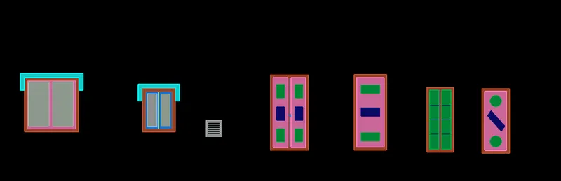
- Place it where the opening are their in the ground floor & first floor.
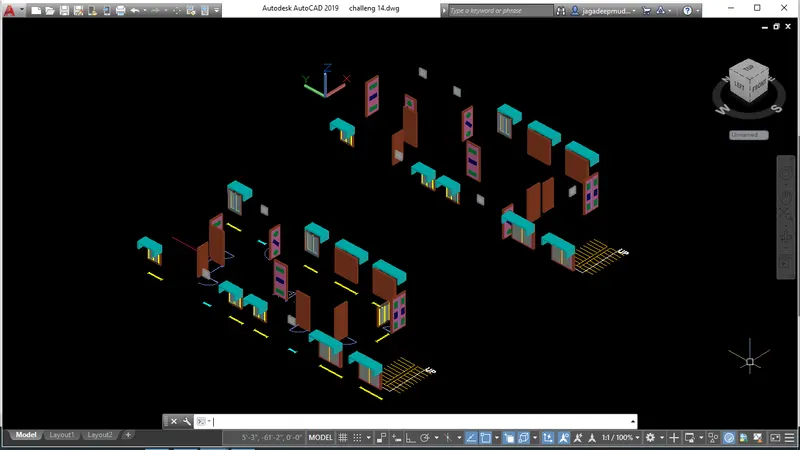
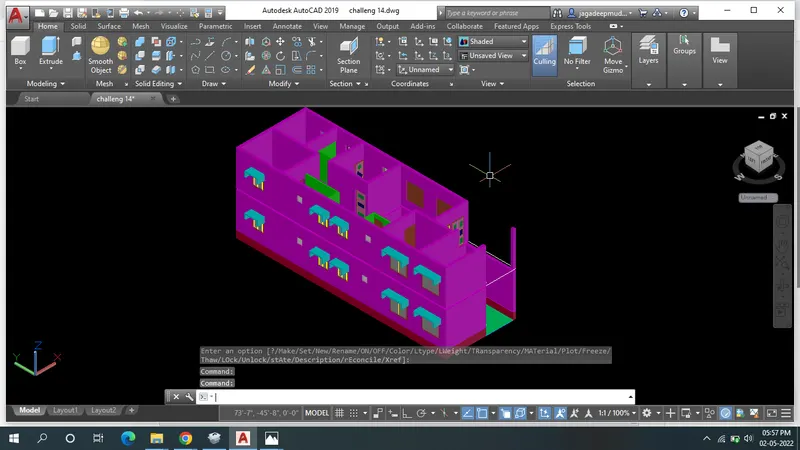
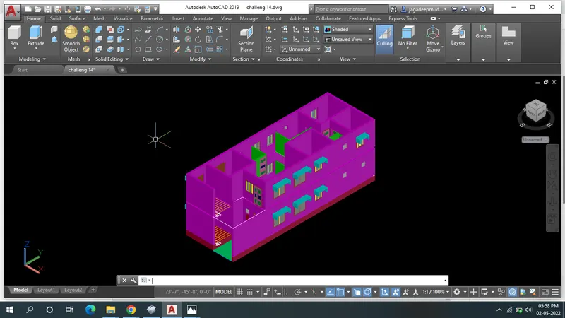
- Use the UCS command create the slab & give the thickness as 5"
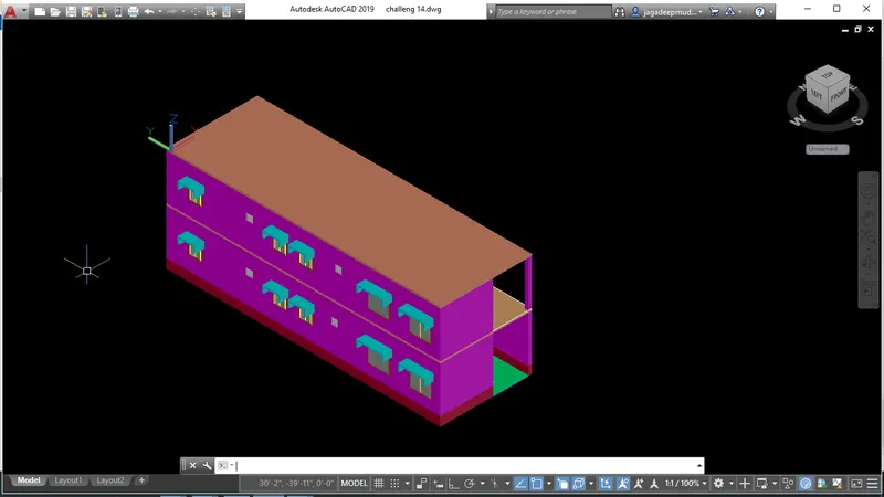
- create the railling in the first floor right.
- create the UCS in the floor & create the circle.
- Type the array command give the distance of the circle & create the another side also.
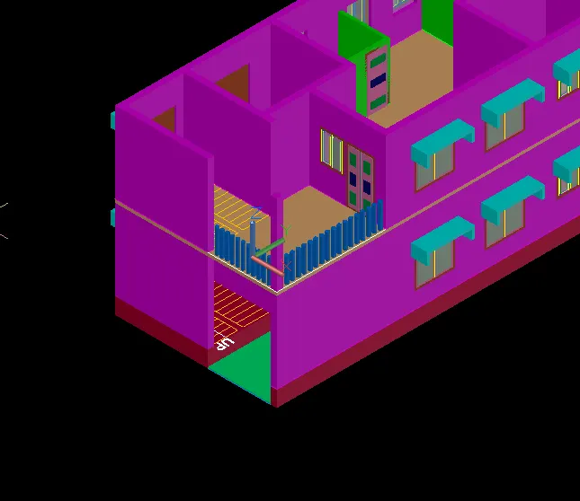
- create the handrail use the line command draw the line & join the line.
- create the small rectangle & use the sweep command.
- first select the oblect of rectangle & select the line press enter.
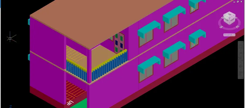
- Create the parapetwall above the slab.
- Presspull the first floor slab face extrude it 1' for both the side.
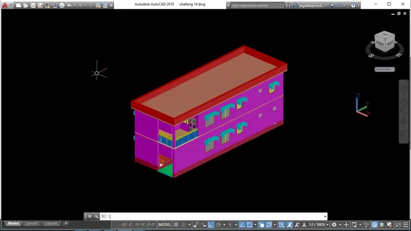
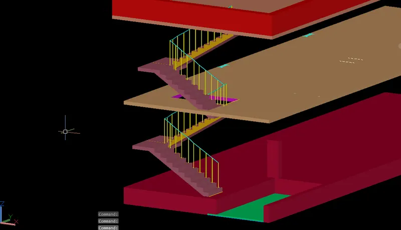
- Create the staircase.
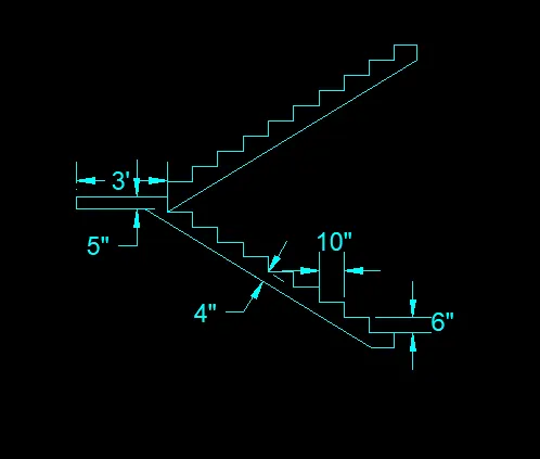
- create the region & boundry.
- use the extrude command extrude it 3'2".
- give the rise height as 6" & tread as 10".
- landing distance as 3'.
- create the handrails height as 3'.
- Create the circle in the side of the staircase.
- use the extrude command & extrude it.
- Draw the line in the above the circle & join the lines.
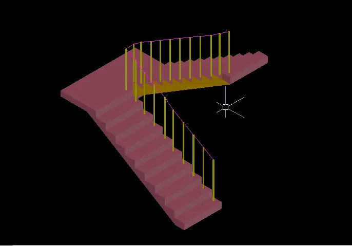
- Create the another circle & use the sweep commmand.
- Assign the circle in the line.
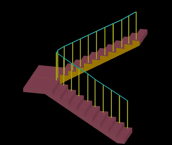
- Place it in the staircase to the residential building.
- ground floor & first floor.
- IN the first floor opening will be required.
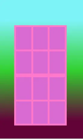
- create the front elevation glass windows.
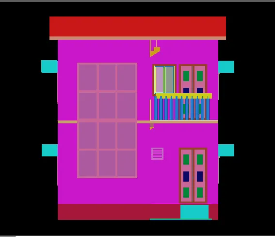
- Place the residential building.
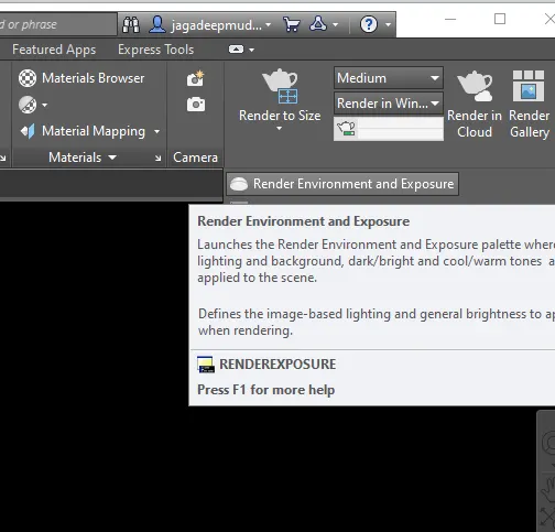
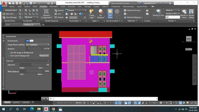
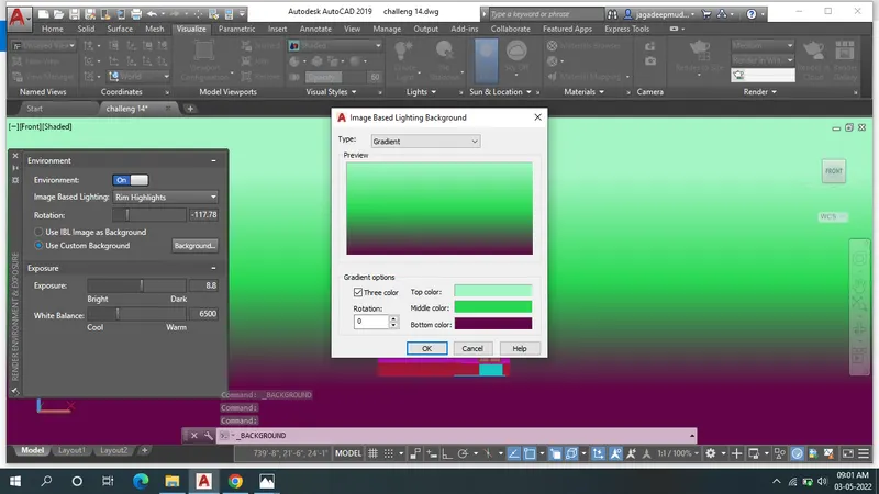
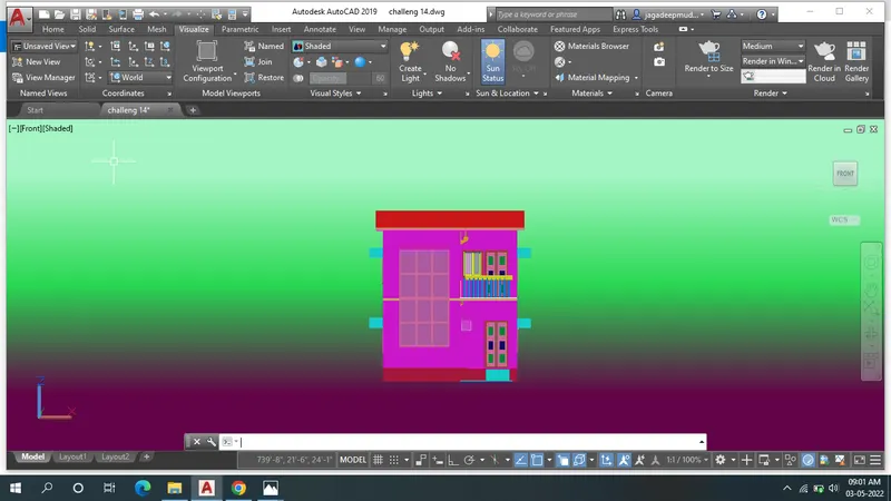
- Click the Visualise in the menubar.
- select the render & click the
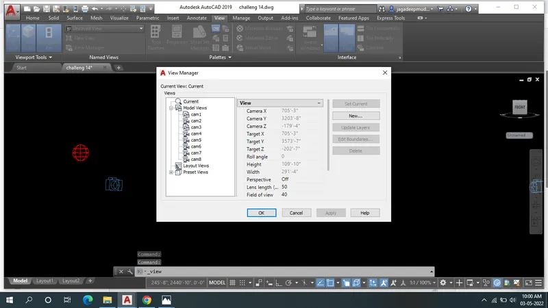
- click the view in menubar.
- create a new view manager.
- place it the lights.
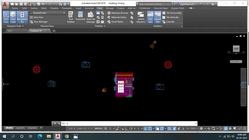
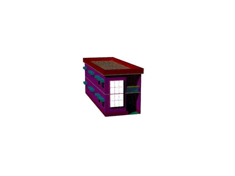
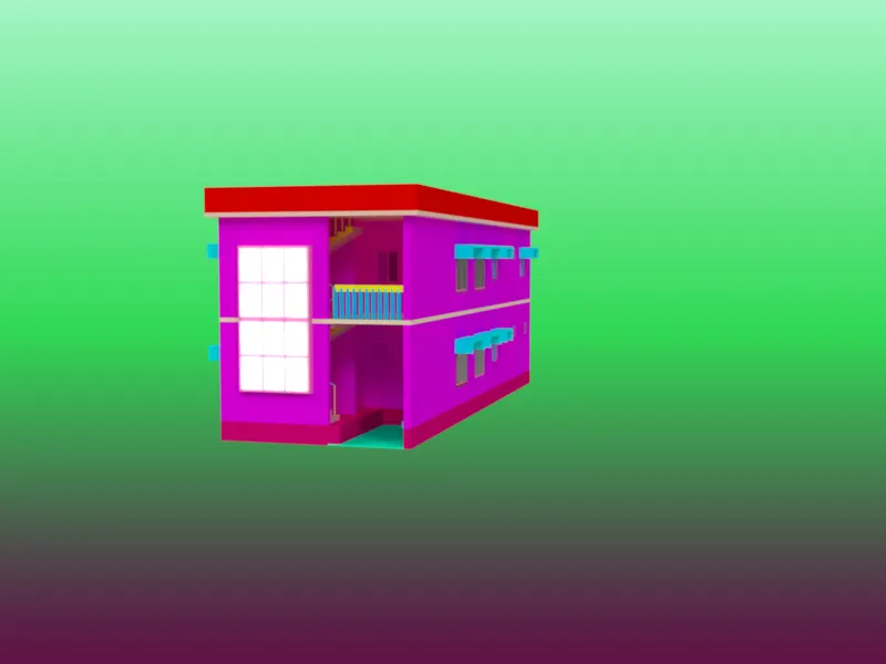
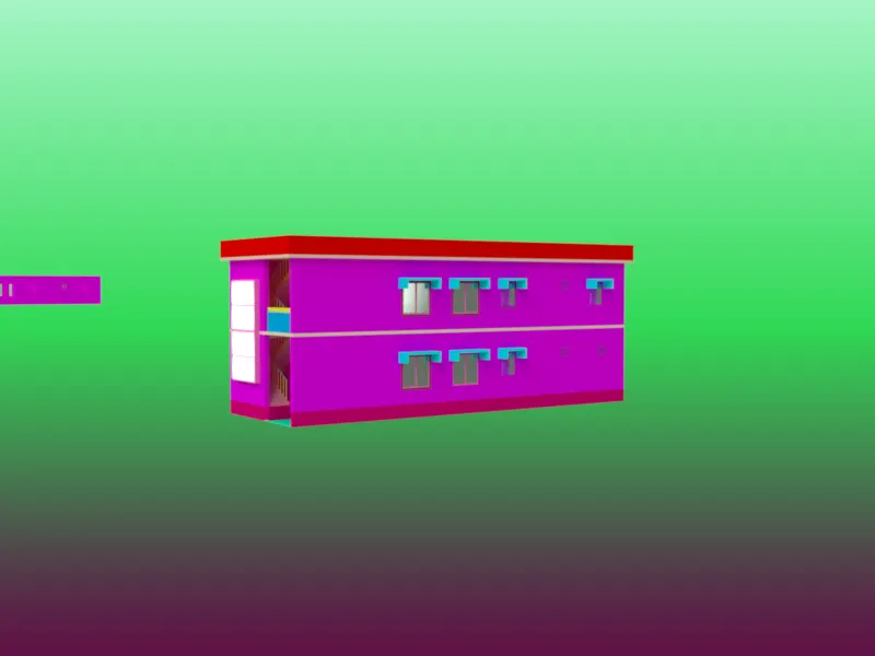
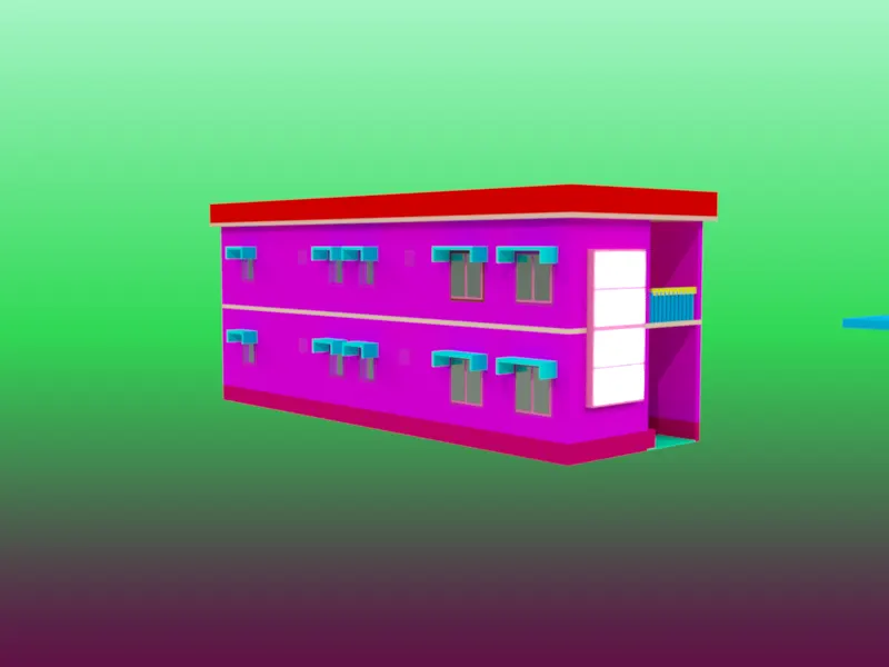
- place the diffrent view & render it to the "rr"command.
Result