Project 2_Analyze and Design the RC office building as per IS standard code in TEKLA STRUCTURAL DESIGNER
Aim - To develop arrangement of and analyse the RC building according to all the loads
Procedure -
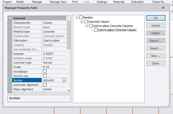
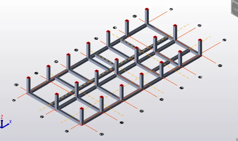
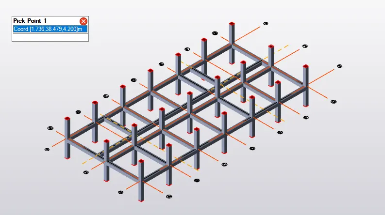
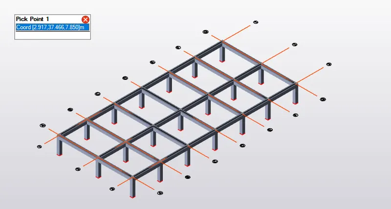
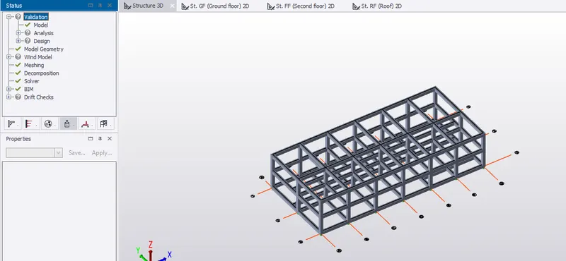
In the home tab invoke manage property sets
There click on new and add
Coloumn in the member
You give all the properties of the soloumn such as grade steel and cover
In teh same add new for slab,pile cap and foundation
In the same way add all the properties of the materials in teh following mentioned below
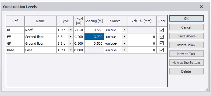
Levels
In the models there is construction lines invoke that command
Then add levels one by one
Base as foundation at 500mm from base
Then first floor at height of 3.7
Second at height of 3.6
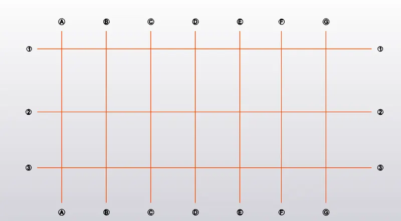
Grids
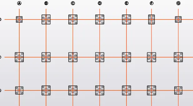
In the same tab there is grids tool
Then draw first grid line
Then select parallel grid line and give distance by clicking F2
Do same to all the grids
The give perpendicular distance
Then give parallel to all the grids
Now manage propert sets
Beams B1 M55 and size 600x600
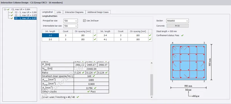
Coloumn M55 and size 900x900
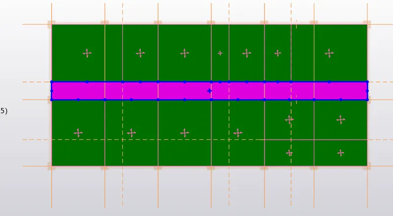
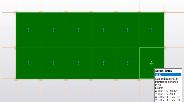
Then slab of thickness 600 slab on beams one way and two way
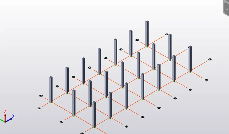
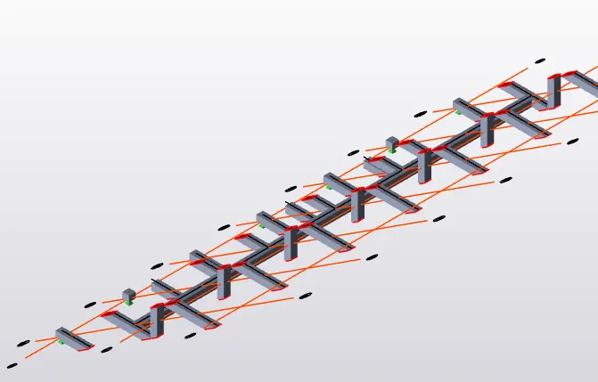
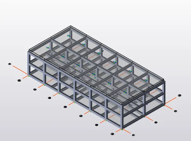
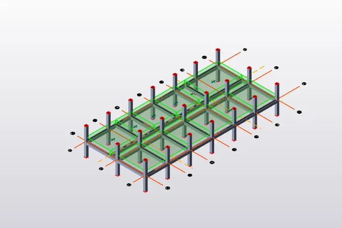
Model in the grids in all the floors according to plan given
Dead loads
Finishers as given 0.05m
0.05m x 24Kn/m2(density)
=0.24
Brick wall load
Wall thickness 1540mm
For ground floor height is 5.5m
20x0.150x5.5
= 11.1Kn/m
For first floor
height is 10.95m
Then load is = 10.95Kn/m
Slab load is calculated by the software
Ceiling is 1.5Kn/m
DEAD LOADS
Then loads
In the load cases in the loads tab
See weather all the loads are there are not if not add new as wind and type as wind
Seismic as seismic type
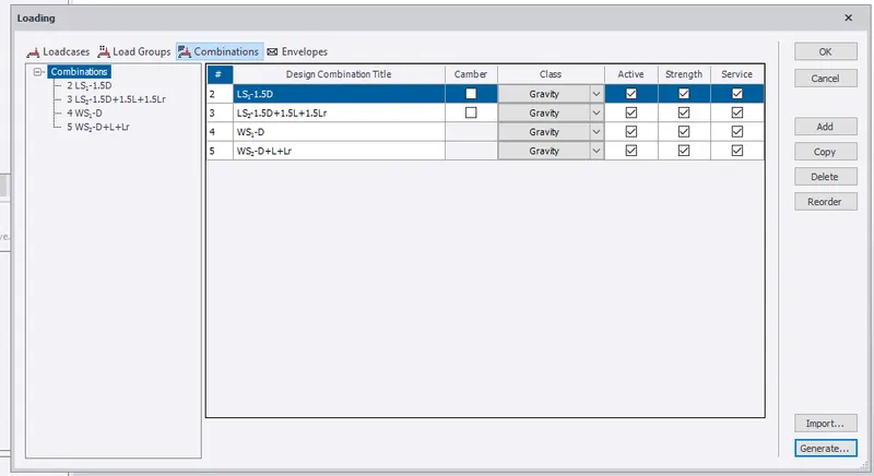
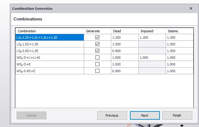
Then go to load combo
Generate new load combo
Table then see all the load combos and next and finish
If you want to add new combo add new
Dead loads are already calculated
Self weight is calculated by software itself
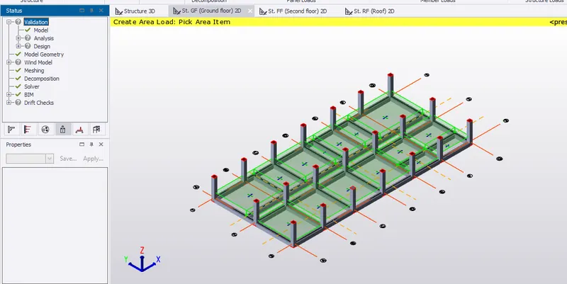
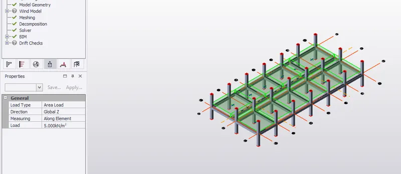
Finishers loads
1.2 KN/m2
Select dead in the bottom left bar
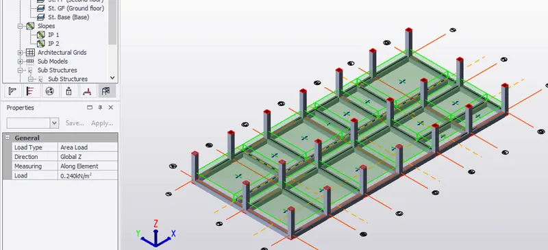
Then add area load give value as 1.2
Select all the slabs it will add the loads
Check in 3d
Do in all the floors
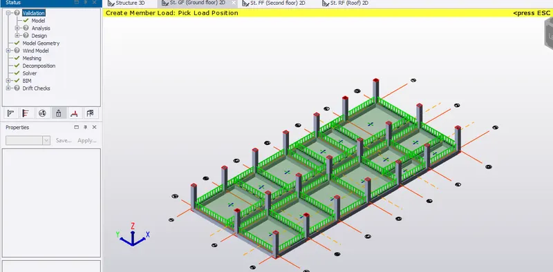
Wall loads
Ground floor
11.1 KN/m2
Select dead in the bottom left bar
Then add line load give value as 11.1
Select all the beams it will add the loads
Check in 3d
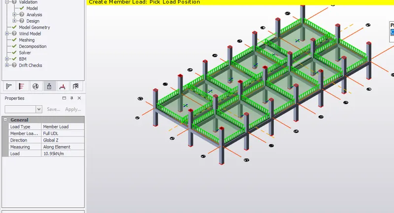
First floor
10.5 KN/m2
Select dead in the bottom left bar
Then add line load give value as 10.5
Select all the beams it will add the loads
Check in 3d
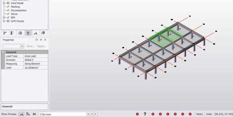
Roof loads
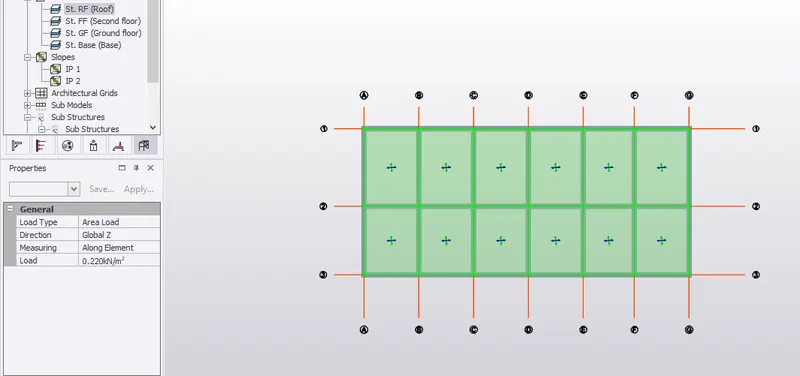
Switch on roof panel
Area load and give load as 1.5
Start applying on teh roof
Validate in every interval and rectify errors
Change load cases to imposed
Give area load and give loads according to is876
Give loads in all the rooms as 3 and 5 KN/m2
In all the floors do the same as we done before
For roof add 1.5 because it is accesible according to code
Validate in every interval
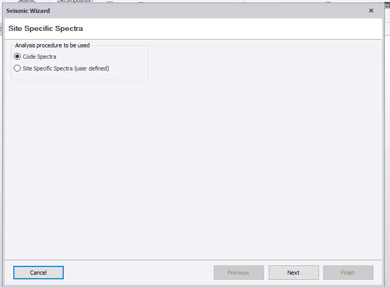
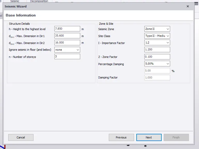
n trhe load tab select seismic load
Then select seismic load wizard
Select code spectra and next
Check all the building parameters
Give as zone 2 and factor of compaction according to code
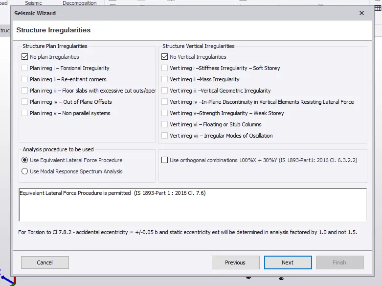
Next and we have no irregularities so click on it and ok
Then give as equivalant lateral force and next
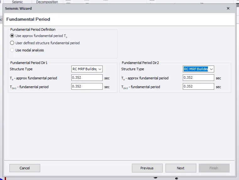
Then approximate fundamental time period and next
Give seismic force resisting system
Give as moment frame system in both dir
Then give RC with OMRF in system
In effective seismic weight select all and shift to right side
See all the combi and service and finish
Then generate and replace and next and next and finish
We have to do the interactive design
Before analysing
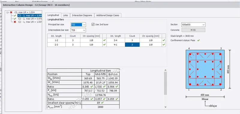
Check all parameters such as cover, grade and reinforcement
Run the analysis
Take any frame
Check deflection for the coloumn
Right click on the coloumn
Chek the coloumn is safe or not if not
Then go to interactive design and then to static
Check coloumn one by one
Increase the bar dia first and check
If it is not safe then increase the bar count
If still fails finally increase the section size it will be passed
Do this for all the coloumns until they are safe
Do it frame by frame
Change the stirrups dia as 10
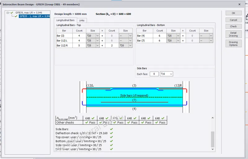
Check deflection for the beam
It is also just like the coloumn
Right click on the beam
Chek the coloumn is safe or not if not
Then go to interactive design and then to static
Check beam one by one
Increase the bar dia first and check
If it is not safe then increase the bar count
If still fails finally increase the section size it will be passed
Do this for all the coloumns until they are safe
Do it frame by frame
Slab design
Firstly check the reinforcement details in the settings
Give the min and max reinforcement and give numbers also
Go to any one of the floor
Makes only slabs as visible
Check all the properties
Fe415, bar dia as 10, c/c dist as 175 and cover
Now check one by one slab
Select one slab and right click and check panel
Then see it is ok or if not ok
Check whick one is not satisfied
If its failing in bending
Firstly decrease the spacing
If its still failing increase the bar dia
Thne check again do until member passes
Do the same thing on all the slabs
On the roof it has more load so increse the steel required
Follow the same process
In the review view check the member failing or safe
Foundation design
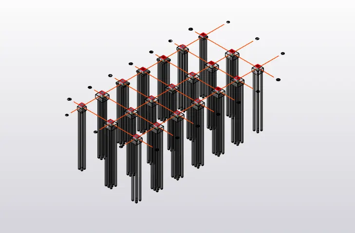
Let us design the pile foundation for this model
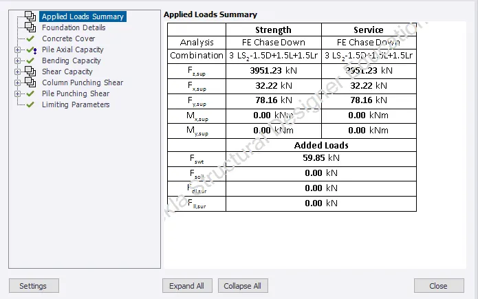
Check the base reactions first in all directions
Now design foundation
Firstly in the settings
Go to foundtion>pile cap
Give bar size and spacing
Give foundation sizes
Give pile length and dia and shape
Go to base again
Define pile properties in the catalogue
Name as P1 and installation is driven
Type as end bearing
Then give pile capacity also
In the foundation tab
Select pile cap coloumn
Drag to all the foundations
Now one by one select all the coloumns
Design member
Then check member
Check all the parameters
If not meet the parameters increse the pile members and bar sizes and pile dia also
Change orientation if needed
Increase the pile placing also if needed
Can increase the pile depth also if fails in punching shear
In the review tab check status
For piles and pile cap
After the analysis and design
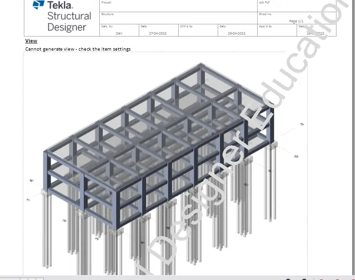
Finally we have to generate the report for model
Firstly do analysis
Then select report in the ribbon
Then select model report
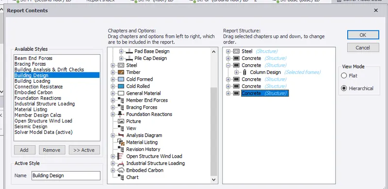
Box appears which contains all the parameters which you want to reported
Drag the parameters to right side which you wanted to report
Since it is a RC structure select
Select In concrete beam,coloumn and pile and pile cap also
To the right side drag all
You can check the summary in the report index
You can also import to pdf also
You can edit header,footer....also
If you want to report only particular floor for beam member
Go to the beam member right click
Model filter edit and add then select the floor you wanted then OK
In the same you can select the frames for coloumns also
Then show reports
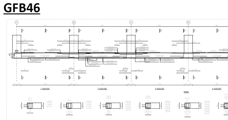
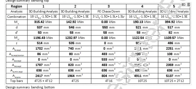
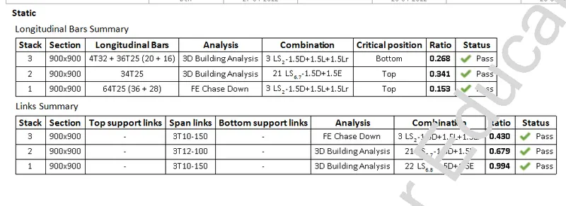
In the reports all the parameters are included
You can also add the pictures
We have choosen moment and shear also and axial though
The forces base reactions
We can check one by one sway,wind drift
You can also report the member individually
Select the member and right click then report member
Then in the model member tab select the parameters and drag
We can select the typical member and do it
We can add teh picture of the moment , shear and axial
Drag the wall design , slab mat design in the concrete also
We have added the analysis diagram and 1d and select the frame
A nd the load combinations added on the diagrams