Project 2 Adaptive Cruise Control
As per requirement we had created a simulink model for adaptive cruise control feature:
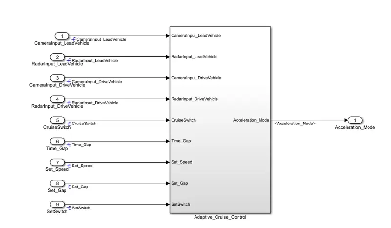
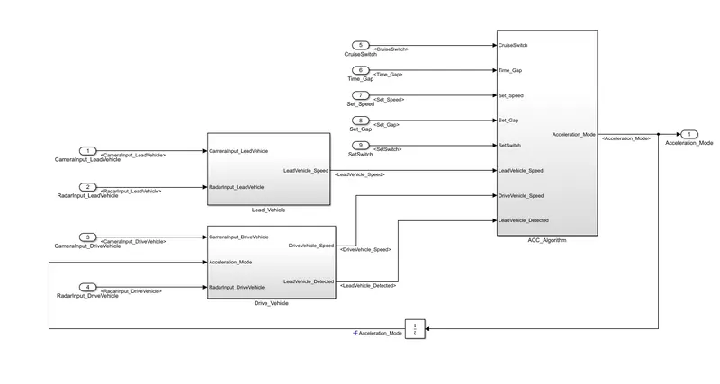
Here consist of three requirement subsystems,
Requirement 1: Lead vehicle subsystem
Requirement 2 : Drive Vehicle Subsystem
Requirement 3 : Adaptive Cruise Control subsystem
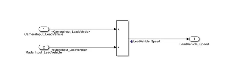
Requirement 1:
As to find out the lead vehicle speed is quite complicated, for simplicity as per the requirement 1, the input from CameraInput_LeadVehicle signal and RadarInput_LeadVehicle signal are summed up to get the LeadVehicle_Speed output.
Requirement 2
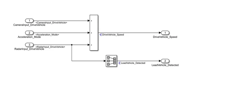
For DriveVehicle_Speed calculation we are adding CameraInput_DriveVehicle, RadarInput_DriveVehicle and Acceleration_Mode feedback from cruise control algorithm.
The outputs from this subsystem as DriveVehicle_Speed and Lead_Vehicle_Detected by propagating RadarInput_DriveVehicle into the signal conversion block.
Requirement 3:
In this subsystem we are using a state flow logics to implement the requirements 3a,3b,3c,3c(i),3c(ii),3c(iii),3c(iv),3c(v),3c(vi).
The inputs for the stateflow are:
Time_Gap
Set_Speed
Set_Gap
CruiseSwitch
SetSwitch
DriveVehicle_Speed from Requirement 2 subsystem
LeadVehicle_Speed from requirement 1 subsystem
LeadVehicle_Detected from requirement2 subsystem
The output from this subsystem is:
Acceleration_Mode - Based on the LeadVehicle_Speed the Acceleration_Mode adjusts its controlling acceleration given output to maintain constant speed.
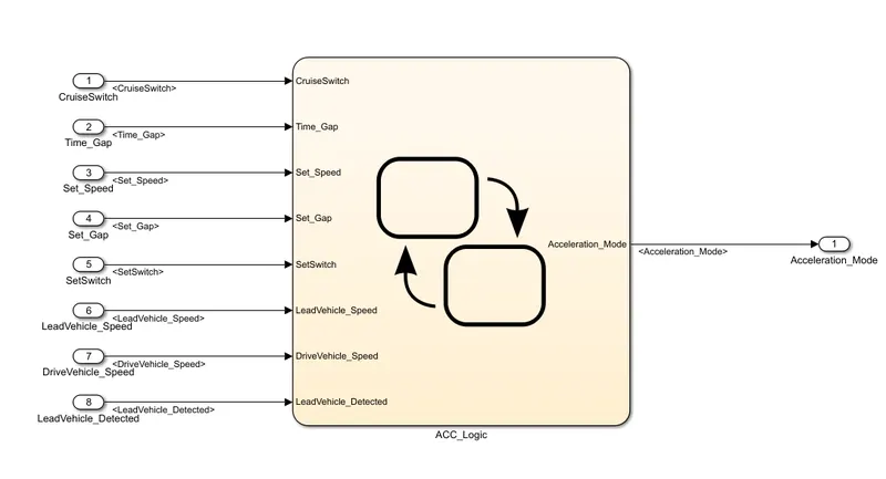
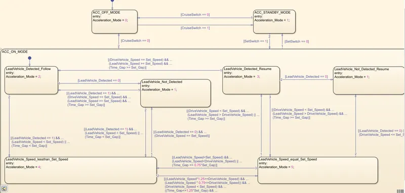
In this logic we had created three modes of operation as :
1.ACC_OFF mode
2.ACC_STANDBY mode
3.ACC_ON mode
In ACC_ON mode we have further 6 modes of operation as:
LeadVehicle_Detected_Follow (Default)
LeadVehicle_Not_Detected
LeadVehicle_Detected_Resume
LeadVehicle_Not_Detected_Resume
LeadVehicle_Speed_lessthan_Set_Speed
LeadVehicle_Speed_equal_Set_Speed
All these modes of operation are modelled as per the given as mentioned in requirements section.
SLDD file cretaion:
For all the input and output signals resolved and propagated in this model are declared in the SLDD file created as shown below:
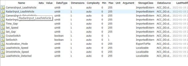
The signal parameters are declared as per the SLDD datatype requirements mentioned above.
The code generated from the output signals are stored in ADAS_CruiseControl.h and ADAS_CruiseControl.c files.
Results:
After compiling the model we are getting 0 errors on the model creation , justifies our logic on modelling for requirements are correct.
Model Advisor Check
For the model check MAAB guidlines we are getting the report as shown below:
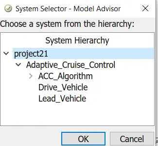
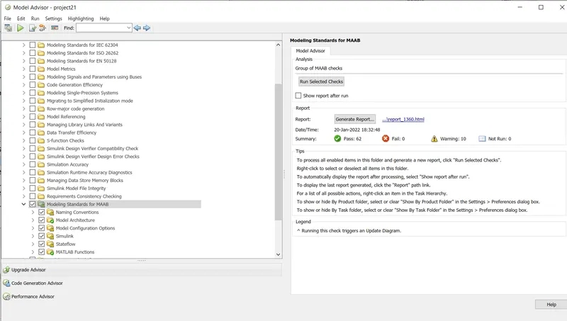
The report for model advisor check attached with this project submission
Requirement Tagging
The word file is used for requirement tagging for the three requirements.
Code generation
File: ert_main.c

1	/*
2	 * File: ert_main.c
3	 *
4	 * Code generated for Simulink model 'project21'.
5	 *
6	 * Model version                  : 1.0
7	 * Simulink Coder version         : 9.2 (R2019b) 18-Jul-2019
8	 * C/C++ source code generated on : Thu Jan 20 21:19:13 2022
9	 *
10	 * Target selection: ert.tlc
11	 * Embedded hardware selection: Intel->x86-64 (Windows64)
12	 * Code generation objectives: Unspecified
13	 * Validation result: Not run
14	 */
15
16	#include <stddef.h>
17	#include <stdio.h>              /* This ert_main.c example uses printf/fflush */
18	#include "project21.h"                 /* Model's header file */
19	#include "rtwtypes.h"
20
21	/*
22	 * Associating rt_OneStep with a real-time clock or interrupt service routine
23	 * is what makes the generated code "real-time".  The function rt_OneStep is
24	 * always associated with the base rate of the model.  Subrates are managed
25	 * by the base rate from inside the generated code.  Enabling/disabling
26	 * interrupts and floating point context switches are target specific.  This
27	 * example code indicates where these should take place relative to executing
28	 * the generated code step function.  Overrun behavior should be tailored to
29	 * your application needs.  This example simply sets an error status in the
30	 * real-time model and returns from rt_OneStep.
31	 */
32	void rt_OneStep(void);
33	void rt_OneStep(void)
34	{
35	  static boolean_T OverrunFlag = false;
36
37	  /* Disable interrupts here */
38
39	  /* Check for overrun */
40	  if (OverrunFlag) {
41	    rtmSetErrorStatus(project21_M, "Overrun");
42	    return;
43	  }
44
45	  OverrunFlag = true;
46
47	  /* Save FPU context here (if necessary) */
48	  /* Re-enable timer or interrupt here */
49	  /* Set model inputs here */
50
51	  /* Step the model */
52	  project21_step();
53
54	  /* Get model outputs here */
55
56	  /* Indicate task complete */
57	  OverrunFlag = false;
58
59	  /* Disable interrupts here */
60	  /* Restore FPU context here (if necessary) */
61	  /* Enable interrupts here */
62	}
63
64	/*
65	 * The example "main" function illustrates what is required by your
66	 * application code to initialize, execute, and terminate the generated code.
67	 * Attaching rt_OneStep to a real-time clock is target specific.  This example
68	 * illustrates how you do this relative to initializing the model.
69	 */
70	int_T main(int_T argc, const char *argv[])
71	{
72	  /* Unused arguments */
73	  (void)(argc);
74	  (void)(argv);
75
76	  /* Initialize model */
77	  project21_initialize();
78
79	  /* Attach rt_OneStep to a timer or interrupt service routine with
80	   * period 0.01 seconds (the model's base sample time) here.  The
81	   * call syntax for rt_OneStep is
82	   *
83	   *  rt_OneStep();
84	   */
85	  printf("Warning: The simulation will run forever. "
86	         "Generated ERT main won't simulate model step behavior. "
87	         "To change this behavior select the 'MAT-file logging' option.\n");
88	  fflush((NULL));
89	  while (rtmGetErrorStatus(project21_M) == (NULL)) {
90	    /*  Perform other application tasks here */
91	  }
92
93	  /* Disable rt_OneStep() here */
94
95	  /* Terminate model */
96	  project21_terminate();
97	  return 0;
98	}
99
100	/*
101	 * File trailer for generated code.
102	 *
103	 * [EOF]
104	 */
105