Final Project: Design of an Electric Vehicle
Create a MATLAB model of electric car which uses a battery and a DC motor. Choose suitable blocks from Powertrain block set. Prepare a report about your model including following:
Objectives:
1. System level configurations
2. Model parameters
3. Results
4. Conclusion
ans
An electric vehicle is defined as a vehicle that uses an electric motor or traction motor for propulsion as opposed to an internal combustion engine used by conventional vehicles. Electric vehicles use electricity for power instead of fossil fuels as conventional vehicles would and because of this difference electric vehicles not produce any exhaust gases or pollution. The power needed for the operation of an electric vehicle can come from a variety of sources such as batteries generator or through collector system. Battery is fitted into the body of an electric vehicle are capable of high energy densities for them to meet the power demands and range requirements. Generators are machines with generate electrical energy from an input of mechanical work and are part of electric motor and they operate during braking to produce the phenomenon of regenerative braking. Collector systems are of vehicle systems which allow for the charging of an electric vehicle from homes of public charging stations. The electricity used for charging in these systems are generated from solar panels which can be used by grade or by homes of EV owners so that they can charge their vehicles more conveniently.
Electric vehicles are increasing in demand in recent years due to the need to reduce the vehicle emissions which are damaging the environment government incentives and private companies are working on schemes to kick and the adoption of electric vehicles since electric vehicles do not produce any missions they are more environmentally friendly than conventional vehicles are. The generation of electricity used to charge the vehicles also comes from solar energy and not fossil fuels which makes them sustainable. Electric vehicles can meet the same
performance standards of conventional vehicles and even surpass that they of theirs and this has been seen with the automotive company Tesla. The Tesla model 3 e is the best selling electric vehicle in the world and is capable of range of approximately 350 km on single charge. It also has an acceleration of 0-60 mph in 5.6 seconds any top speed of 130mph.
Electric vehicles offer several advantages over conventional vehicles beside the lack of pollution and lack of need to rely on fossil fuels one is that electric vehicles are more efficient meaning that they offer more miles per gallon gasoline equivalent meaning that you will spend less on recharging the every then you would be to refuel a conventional vehicle. This because the more efficient the electric vehicle is the more distance you travel with the available energy. In US Tesla owners can charge their electric vehicles for free at their private charging stations for life which results in significant savings in fuel. Regenerative braking in electric vehicles add to their efficiency as the unused energy in the baking gets reused purposefully. Another benefit of the electric vehicles that have a moving or rotating parts and this means lesson maintenance cost then you would have with IC engine vehicles example changing oil transmission fluid. This in long term would give then you would get with conventional vehicles. Lesser moving parts means there is less and friction between moving parts and hands quieter operation.
In spite of these feeds it will be difficult for the worldwide adoption of EVs for several reasons. One reason is convenience. In order for EV to dominate the automatic market their needs to be more convenient ways for consumers to be able to charge your vehicle's their needs to be several charging stations on the Highways and roads and this can be supported in SAP B1 homes where generating solar power it needs to be an easy to charge electric vehicle as it is to feel and IC engine vehicle with fuel at a petrol station another reason is the cost of the EVs.EVs are still a relatively new technology and only account for 2-3% of the worldwide market. This is because they caused considerable more than conventional vehicles due to high cost of batteries an electric components. But the cost of the battery is getting cheaper over time and manufacturers are developing new and more efficient batteries the goal is to produce a million MI battery which is made will be revolution in the automatic sector and other disadvantage is that components in the EV operate at high voltages and currents and this can be a hazard with the components explore don't work as they should.
A compromise between IC engine vehicles and EV exist as Hybrid electric vehicles Hybrid electric vehicles combine and IC engine with an electric propulsion system to produce a hybrid between the two different classes of vehicles the purpose of this is to use power available from electric powertrain to improve the fuel economy of the vehicle so that it does not rely solely on the petrol or diesel it uses as well this in turn also will improve the overall performance of the Hybrid electric vehicle IC engine can be used to power the electric motor to charge the battery or use directly in the electric drive motor with combination of motor and generator in one. Hybrid electric vehicle also implement regenerative braking to recharge their battery is among the other features used in electric vehicles. Compare two electric vehicles Hybrid electric vehicles are present more of the automatic market with 19% market share on all automobiles in the world this is because Hybrid electric vehicle still run on fossil fuels which is still more convenient as a fuel source in most parts of the world the all-time bestseller today it is a Toyota Prius.
In this report I will be Modelling and electric vehicle with DC motor and battery system using simulink software. The components I will need for my model exist as blocks in the simulink library. I will be modelling this electric vehicle for a drive cycle and measure the velocity characteristics and the current and the state of charge characteristics of its battery system.
Components:
The main components of an EV are:
Batteries
Power converter
Motor controller
Motor or generator
Transmission system
Wheels or tires
Battery store the electrical energy needed to power the electric vehicle in all of its system and needs power converters convert the power coming from the battery to a usable form for the motor live conversion can be done from DC to AC or vice versa and can even be between two different magnitude of DC to DC or AC to AC. Motor controllers are electronic switch control the amount of power delivered to the motor wire control signal so that the motor is running as,nded used for propulsion in order to move the vehicle in forward or reverse motoring there in generator is a part of motor and just works on the opposite method to the motor when braking the vehicle can generate electricity and send his power back to the battery charging it. The transmission system is need for the vehicle to change speeds as it accelerates or decelerate. The wheels are needed for traction on the roads and depending on the powertrain electric vehicle maybe and forward wheel drive or rear wheel drive. If the vehicle is an forward wheel drive only the front axle which produce propulsion and if it is and real wheel drive the back axle wheels produce it instead all wheel drive where the front and rear wheels work together to produce propulsion.
System level configuration:
The model and electric vehicle in simulink we will need to model the aforementioned component separately and then have them work together all the main components are available in the library of simulink in blocks and we will be adding each component and configuring it parameters to fit the requirements of the model first I have model the vehicle main body.
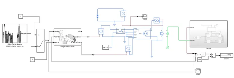
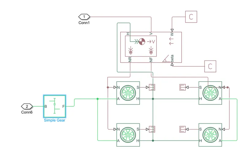
Vehicle body
To model the body of a vehicle we need to first add the vehicle body block and this is shown below
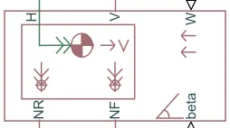
The block contains exports which can be used to model the various aspects of the vehicle body the ports are mentioned and elaborated below:
H - this stands for hub and is used to connect the hubs of the wheels to the main body of the vehicle
V - this is a physical signal output port which stands for velocity and is used to output the speed velocity at which the vehicle is moving
W - this is a physical signal input port and allows us to model a wide wind acting on vehicle by giving a speed for it
NR - this is a physical signal output Porter model the real normal forces
NF - this is a physical signal output to model the front wheel normal forces
beta - this is a physical signal input port and allows us to model the vehicle on inclination angle and to create the effect of Hill Climbing force
If we double click the vehicle body block ok we can see and modify its parameters the image below :
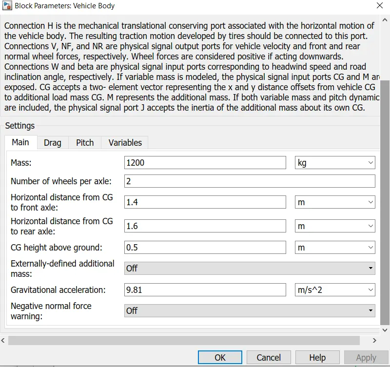
As you can see we are able to modify various parameters of the vehicle body example mass number of each per axle distance of the centre of gravity to the front and rear axles these are main parameters and have been left with the default values assigned when the block was added to the workspace the next tab shows the parameters for drag and this is shown below
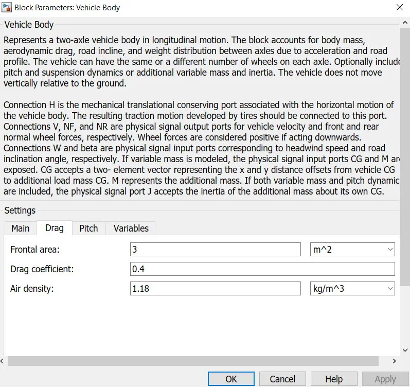
We can see from this image that the parameters of frontal area drag coefficient and air density can be modified in order to effect the drag force acting on the vehicle in my case I have only change the drag coefficient to 0.4 in order for the model to resemble a typical sedan. Air density and frontal area and normal for this type of vehicle.
Tires
The tyres used in this electric vehicle model are the magic formula tyres there are several tyre block that can be used for modelling a vehicle but I have use magic formula once because it allows us to model the longitudinal behaviour of the vehicle Tyres on highways. They allow us to model extra effects such as the inertia stiffness which allows for Greater accuracy of real-world conditions. The magic formula tyre block is shown below.
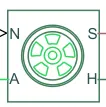
We can see that it has 4 ports and they are :
N - this port stands for normal and is the physical signal input port for the normal force acting on the tire and is considered positive in the downward direction
S - this food stands for slip and is the physical signal output port is reports the slip acting on the tyre
A - this Fort stands for excel and is mechanical rotational conserving port for the wheel axle
H - this port stands for hub and is mechanical translation conserving port for the wheel hub through which the thrust developed by the tiers is applied to the vehicle body
Double-clicking the magic formula tyre block takes us to its parameters
Main
The image below shows the settings for the main parameters of the magic formula tyres
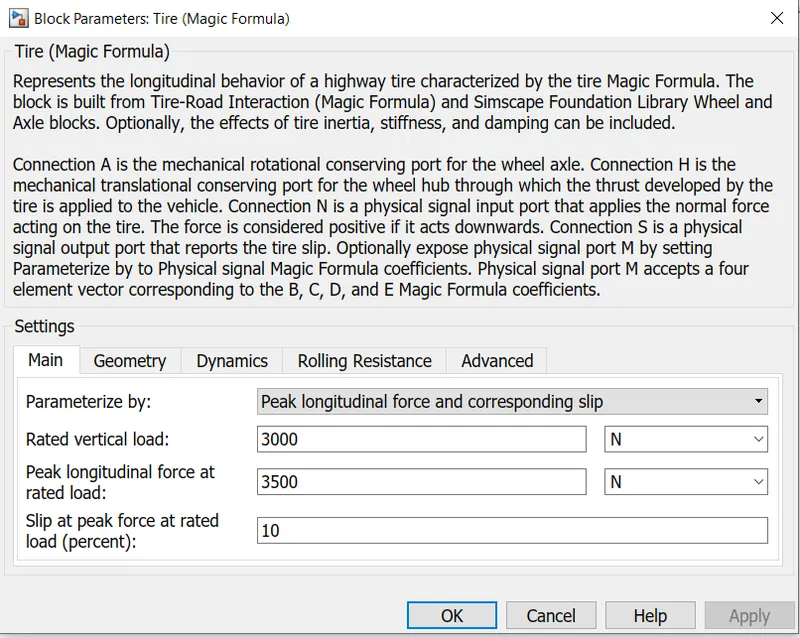
As we can see, we are parameterizing the tyres with load dependent magic formula coefficients and the remaining parameters that follow with it are default.
Geometry
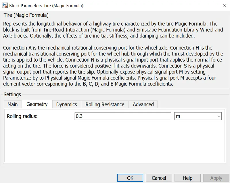
The image below shows the parameters of the tyre geometry there is only one parameter that can be modified and it is the Rolling radius and has been set to nominal value of 0.3m.
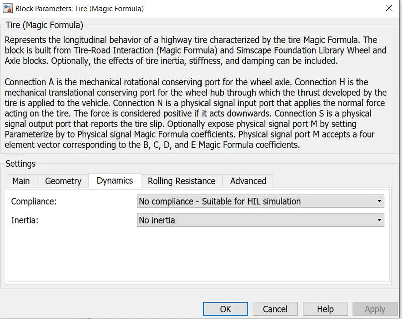
Dynamics
The cost parameters are the Dynamics of the magic formula tyres this is where we can model additional effect example tag inertia and initial velocity if you are modelling to specify this two conditions.
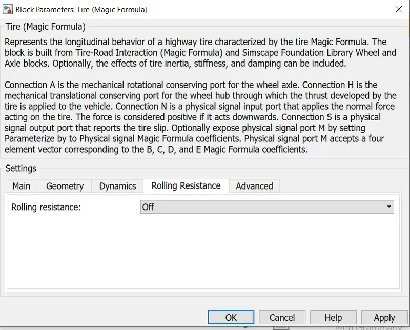
Rolling resistance
Here we can model The Rolling resistance parameters on the tires and I have to choose to switch on the Rolling resistance force on the tires.
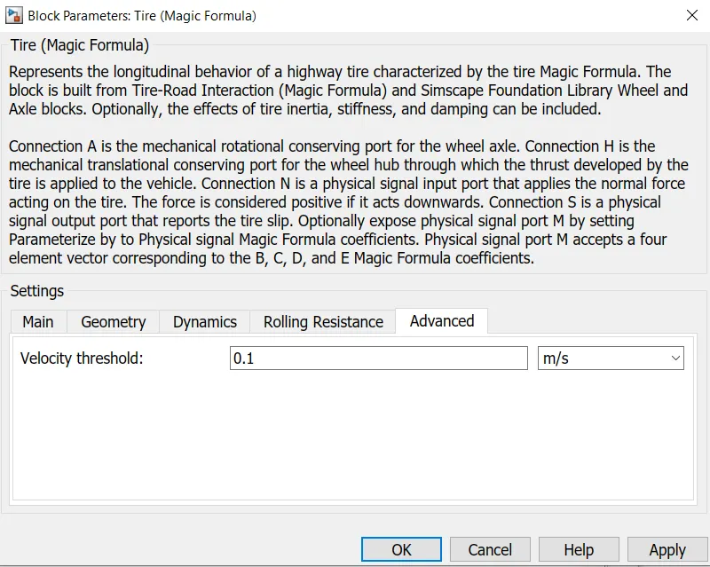
Advanced
Finally the last parameter of the magic formula Tyres is the velocity threshold and this has been set to 0.1m/s. To below the speed the block will not model any of the aforementioned effects of motion on the tyre is called a threshold velocity.
Gear
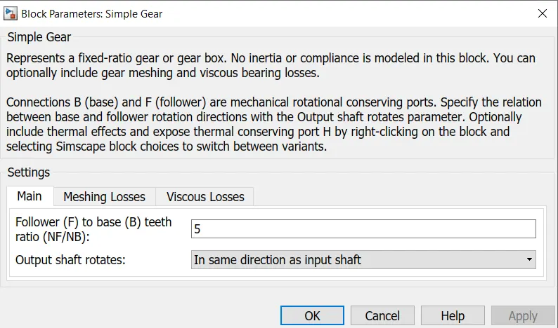
Next we will model the transmission system of electric vehicle I have decided to use a simple gear block so as to simplify the transmission system parameters. This block Model gear system with fixed gear ratio with no inertia effect however we can modify the effects of the machine of the gear teeth the simple gear blocks is shown below.
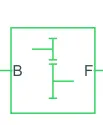
Double-clicking the simple gear block takes us to its parameters.
Main
The main parameters of the simple gear are the follower 2 based IT ratio and this has been set to 5. Also specify the output shaft rotates in the same direction as the input shaft as opposed to the direction of the input shaft.
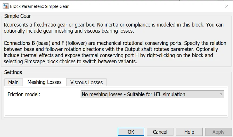
Meshing losses
The meshing losses I have selected no meshing losses- suitable for HIL simulation.
Motor
For electric vehicle model I have selected to use a DC motor block as the motor this is because DC motor are easier to model and have fewer parameters to modify for a particular application for this model a DC motor will do just fine the DC motor block is shown below

As we can see there are two sides to the block the mechanical site on the right and electrical side on the left the mechanical side has two ports c and r the C refers to the casing and R for the rotation of the rotor which produces a torque. The electrical side has a positive and a negative terminal for the voltages to be applied. If a positive voltage is applied to the DC motor block from the positive to the negative terminal of a positive talk will act from the C port to the R port. The direction of the torque produced by the DC motor can be changed by changing the sign of the back EMF or the torque constant. The C put off the mechanical side needs to be connected to the mechanical rotational reference because it will be stationary. The R the port will be connected to open connection of the simple gear from the vehicle body block. The positive terminal on the electrical side is connected to the positive terminal of the power converter which in my case will be an H bridge.
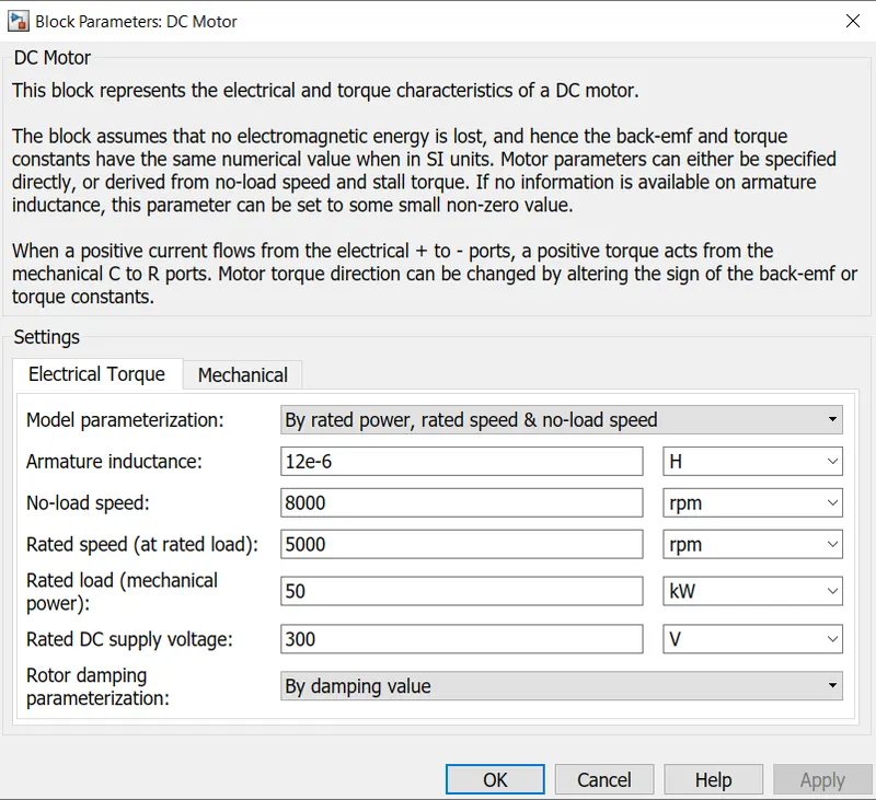
Double-clicking the DC motor block access to its parameters the electrical torque parameters and first considered here I have chosen to parametrize the block By rated power rated speed and no load speed. This lets as modify parameter such as DC supply voltage rated load. This is shown in the image below:
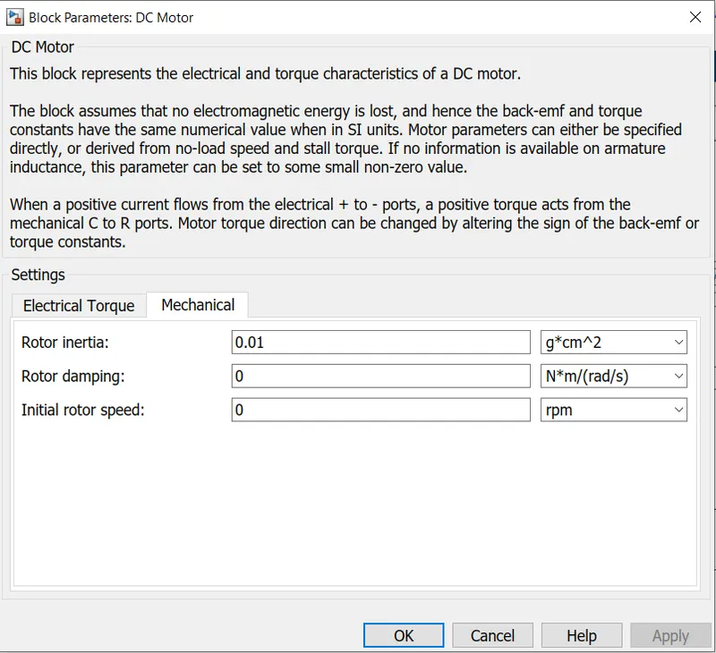
Them mechanical parameters we can modify the rotor inertia damping and initial rotor speed however these values were kept to the default settings
Power converter
The power converter is needed to provide power to the correct form and magnitude from one component to another. In case of electric vehicles a power converter is needed to provide a DC voltage from the battery of the electric vehicle to the DC motor so that it can operate properly with required parameters. As mentioned earlier I have used and H Bridge motor drive as my power converter its block is shown below:
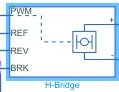
BH Bridge has two sides to it the left side is the controlling of voltage Signals and right side of the terminal is to provide the control voltage to the DC motor the left side ports of the H bridge block are:
PWM - this stands for pulse width modulation which will provide the voltage pulses to the H Bridge weather in pulse-width modulated or average mode.
REF - this is for reference
REV - this stands for reverse
BRK - this stands for brake
Opening the h bridge block will take us to its parameter shown below
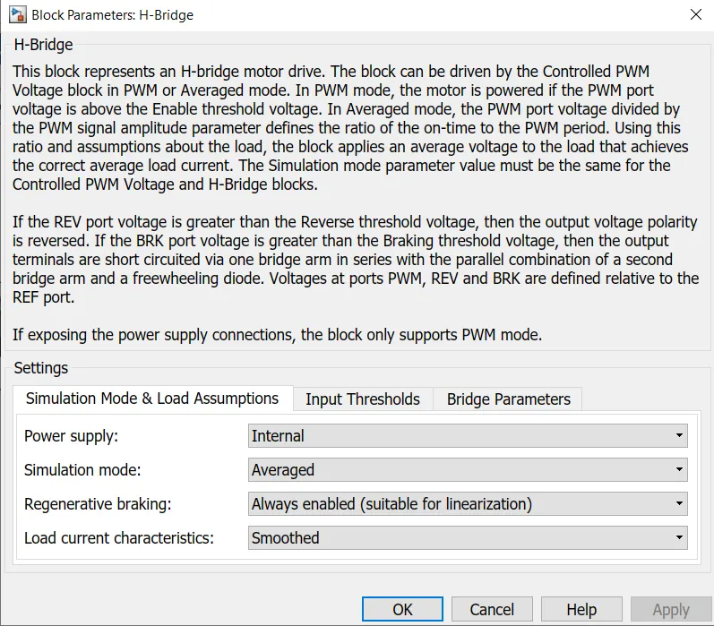
The main parameters are for the simulation mode and load as emissions of the H bridge Aaj. I have selected the H bridge to run on then internal power supply with an average simulation mode instead of pulse width modulated mode this is because using pulse width modulated mode will result in significantly longer simulation X compared to using the average Mod I have enabled the regenerative braking mode and set the load current characteristic to smooth option.
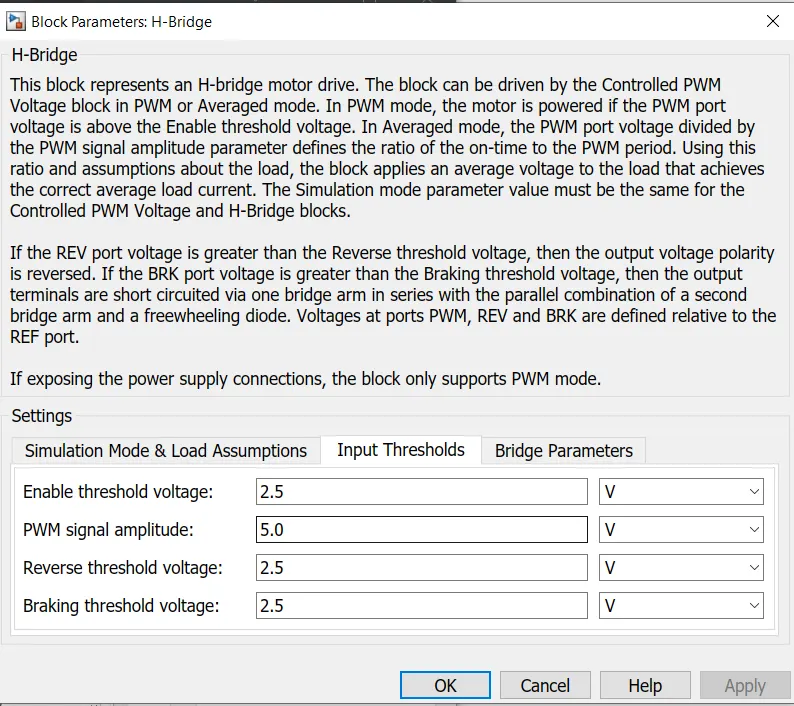
The next parameters of the H the bridge its input threshold. Where we can set the various voltage limits of its 4 left hand side ports. These values are left to the their default settings.
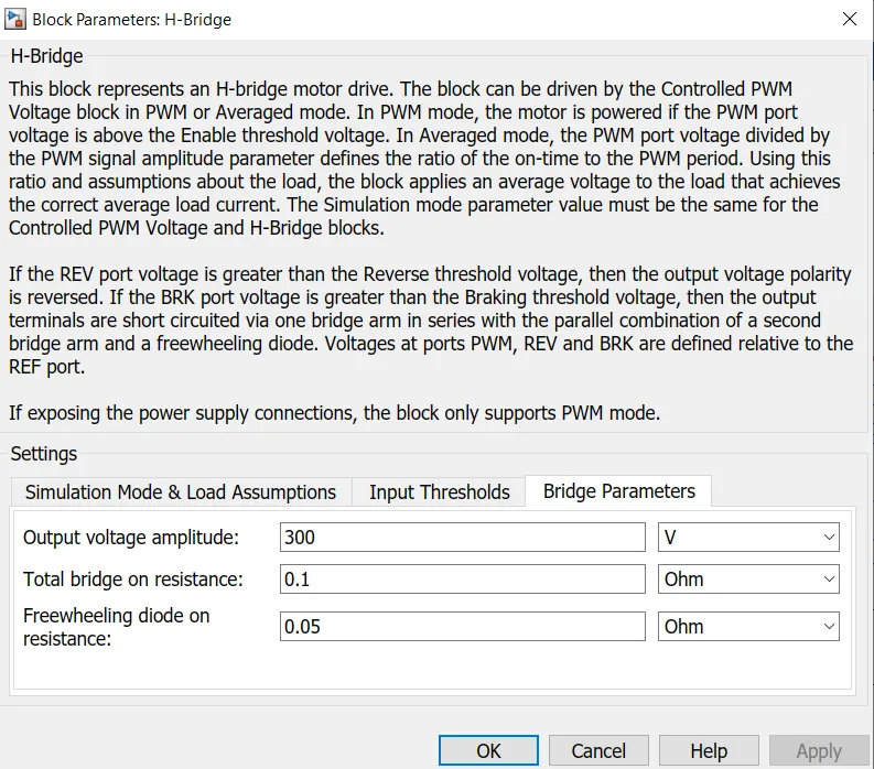
The last parameters for the H bridge parameter is is bridge parameters. Only the first parameter of the output voltage amplitude was modified this is because the DC motor has been parametrize to run on DC supply voltage of 300V so this same value is used for output voltage amplitude.
Once these parameters have been applied close the parameter settings the connections for this block will be made later on.
Controlled PWM voltage
Next I have used controlled pwm voltage block to provide a control pulse width modulated voltage to the H bridge block. The block will output the pwm voltage through its pwm and REF ports which will feed into the same ports found on the h-bridge block. If the pulse is the low the output voltage is considered zero volts whereas if pulse is hide output voltage will be equal to the output voltage amplitude which was set to the 300V in the H bridge block. The pulses of the voltage created by this block and dependent on the duty cycle which is the ratio of the time that the switch is on to the time taken for one cycle. Duty cycle is set by the input of the controlled pwm voltage block.
The duty cycle is given by:
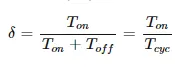
The controlled PWM block is shown below

The block parameters are shown in the image below:
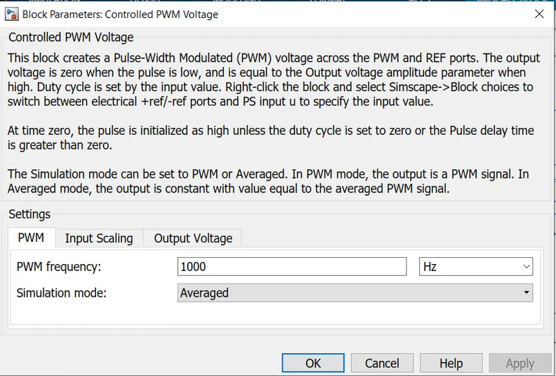
The main settings pertain to the PWM parameters. Here are all the parameters are maintained at the default values if using the average simulation mode so that the average value of the voltage pulses generated and feed into the H Bridge. This will allow for simulation time, just like the H bridge block parameters. The remaining parameters of input scaling and output voltages are unchanged
If these parameters have been applied close the block parameter window the connections for this block will be made later on.
Controlled voltage source
The input ports of the controlled pwm voltage block are still and connected and that is because they require controlled voltage source to provide the voltages to produce the voltage pulses to be fed into the H bridge. For this I have used the control voltage source block. This block is useful because it will provide the necessary voltage that is powerful enough to maintain the voltage at the output regardless of the current that passes through it the this controlled voltage source block is shown below.

Longitudinal driver
The longitudinal driver block is used for giving normalise acceleration and deceleration,commands to a controller based on two sets of data the first data set is reference velocity and second data set is feedback velocity. The longitudinal driver block is shown below
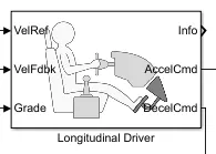
The longitudinal driver blocked has following ports
VelRef - this is for reference velocity and its velocity data provided from drive cycle source
Velfdbk - this stands for the feedback velocity and it is the velocity data provided from the vehicle body velocity vote which output the velocity data
Grade - this report provides a great or inclination angle for the surface on which the vehicle is travelling in degrees
Info - this port is for the bus signals which consists of block calculations example acceleration or deceleration,command, difference between reference and vehicle speed
AccelCmd - this would provide the acceleration command to a controlled voltage source
DecelCmd - this port provides the deceleration command to another controlled voltage source.
The working of the longitudinal driver block is simple difference velocity data coming from drive cycle resource is compared to a feedback velocity data coming from the vehicle body block if the reference velocity is greater than the feedback velocity and acceleration,nd will be put the control voltage source if the reference velocity is less than the feedback velocity decceleration command is given as output to another control voltage source instead for acceleration and deceleration commands to be given as output signals, I have used a simulink in to PS converter block. This block is needed whenever we wish to connect a similar input signal to a physical signal in this case the input signal is velocity data and this is logic data which we want to convert to a physical signal ie. Voltage to the controlled voltage source.
Distance measurement
I have used the scope block and mathematical operator blocks to measure the distance travelled by the vehicle according to the drive cycle data. The area under velocity time graph tells us distance travelled by an object and so in my model. This means that integral of velocity with respect to time gives us the distance travelled so I have implemented the integrator block to integrate the velocity signal that is output from the vehicle subsystem.
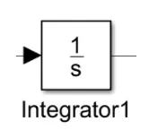
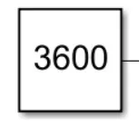
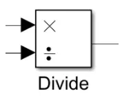
From the integrator block I needed to use the divide block along with the constant block having a value of 3600 in order to convert the divide the integrated speed signal which is in km per hour by 3600. This will give us the distance travelled in kilometres. The constant Block with the value of 3600.
The divide block
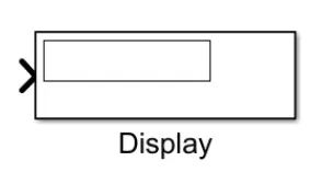
finally a display block is used to show the distance travelled as the simulation is run, the display block is shown below.
If all of these connections have been made, we can begin running the simulation for my EV model
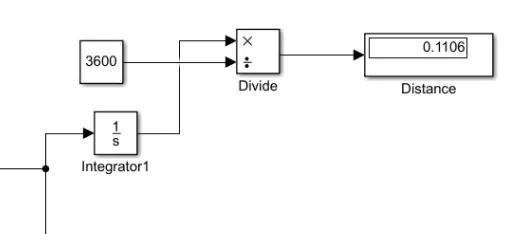
If all the connection have been made we can begin running the simulation for my EV model
Results:
I ran the FTP75 drive cycle for my EV model and took the outputs given from the speed,current. The distance travelled by the vehicle in the drive cycle was also measured using the display block.
speed scope
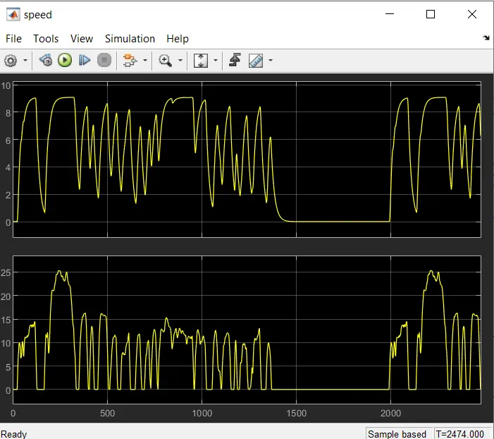
From this scope we can see two signals the second signal is the drive cycle speed vs time whereas the first signal is the speed of the vehicle running for the given drive cycle input.
Current Scope
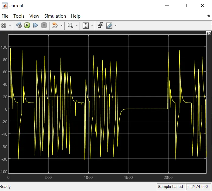
the current scope shows how the current flows from the battery to the motor vsaries with the drive cycle time.
Distance Measurement
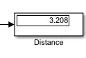
From the image above we can see that the display block has ,measured the distance travelled by my EV model for the given drive cycle.
Conclusion
In conclusion the EV model has been created with the necessary block components using the simulink software and the model has been stimulated for the given drive cycle. The simulation has produced results of the velocity of the vehicle current flowing from the battery and the distance travelled by the EV. Since the EV model uh was parametrized to simulate average voltage pulses in the H bridge and control pwm voltage blocks to be fed into the DC motor, the simulation was Run very quickly within a matter of seconds. The EV model was able to follow the,nds given from the drive cycle data although it could have followed the reference signal is more closely. The discrepancy between the reference voltage and actual velocity of the vehicle may be attributed to a variety of factors example vehicle inertia transmission system transmission inertia. If the EV model was designed in such a way as to improve the spectators the model would follow the reference signals more closely and would improve the performance characteristics as well. Distance travelled by EV model was measured to be 3.208KM e and seems to be appropriate value based on the given drive cycle.
I have uploaded the EV model as a .slx file named evdesign1_S.slx for your reference.