Project 2 Adaptive Cruise Control
PROJECT: ADAPTIVE CRUISE CONTROL
OBJECTIVE:
Adaptive Cruise Control Feature for passenger cars allows the host vehicle to adapt to the speed in line with the flow of traffic. This feature can reduce the stress on the driver by automatically controlling the vehicle speed & maintaining a predefined minimum distance to the preceding vehicle. As a consequence, the driver enjoys more comfort & can concentrate on the road little better.
DESCRIPTION:
A RADAR sensor installed at the front of the vehicle, so it monitors the road. If the road is clear this feature maintains the speed set by the driver. If the system spots a slow vehicle within the ddetection range, it gently reduce the speed by releasing the accelerator. If the vehicle speed is high or changing of lane, the cruise control automatically accelerates to the driver's desired speed.
Steps followed:
1. Requirement analysis
2. Developing model
3. simulate the model
4. Requirement tagging
5. Data Dictionary creation
6. Configuration parameter settings update
7. Model Advisor check
8. Code Generation
SIMULINK MODEL:
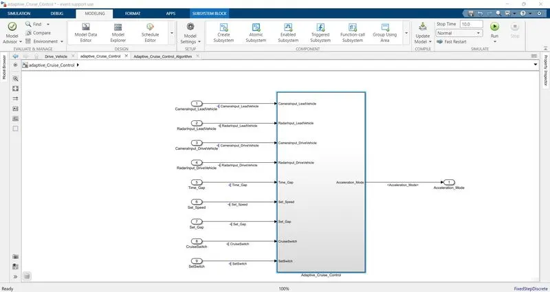
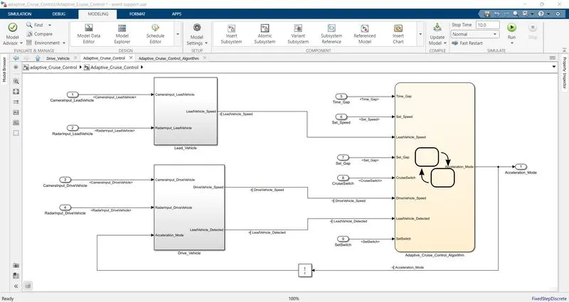
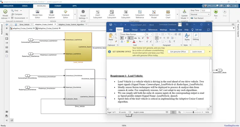
1– Lead Vehicle:
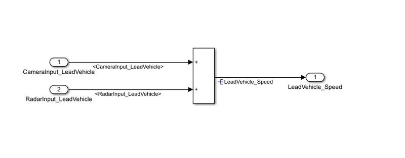
The vehicle which is drive ahead of drive vehicle is the Lead vehicle. This vehicle speed sensed with Radar sensor.
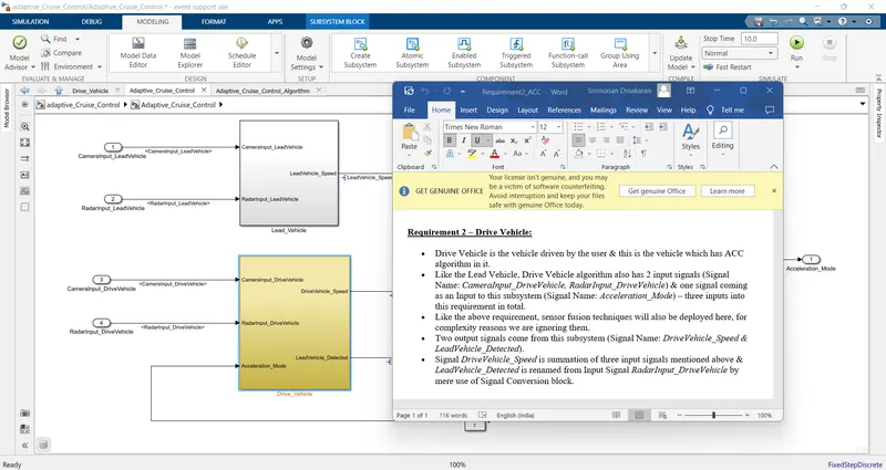
2 – Drive Vehicle:
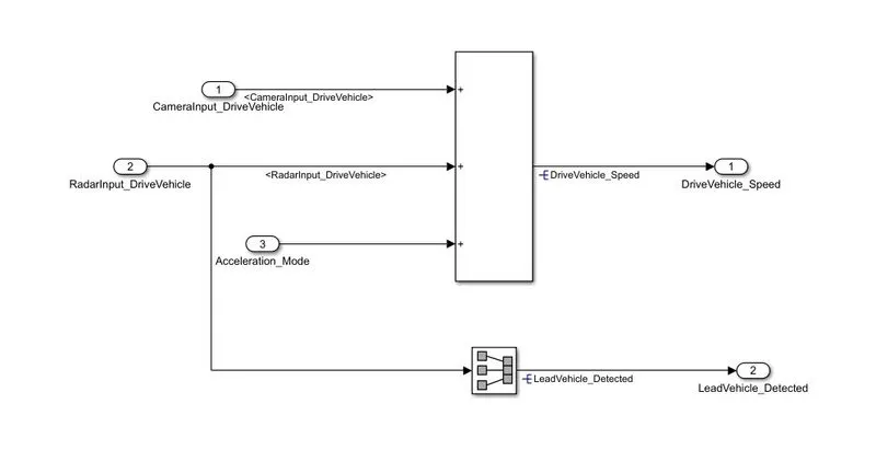
The Vehicle in which ACC algorithm implemented is the Drive vehicle.
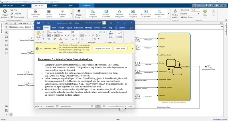
3 – Adaptive Cruise Control Algorithm:
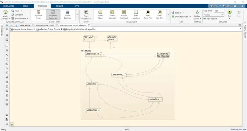
In the Adaptive Cruise Control algorithm the operation takes place in 3 different modes namely, OFF_MODE, STANDBY_MODE, ON_MODE. This algorithm is developed as per the requirement.
REQUIREMENT TAGGING:
The given requirements can be linked with the corresponding blocks or subsystem.
select the required requirement in the word document. then right click by placing the cursor on the corresponding block, select Requirement-> Link with selected word document.
once the requirement tagged, we can check it by block colour change and while right clicking on the block goto requirement, it shows the linked document name at the top.
Requirement 1– Lead Vehicle:
- Lead Vehicle is a vehicle which is driving in the road ahead of our drive vehicle. Two input signals (Signal Name: CameraInput_LeadVehicle & RadarInput_LeadVehicle).
- Ideally sensor fusion techniques will be deployed to process & analyze data from camera & radar. For complexity reasons, let’s not adapt to any such algorithms.
- We can simply add both the radar & camera inputs & the corresponding output is read as Speed profile output (Signal Name: LeadVehicle_Speed).
- Speed data of the lead vehicle is critical in implementing the Adaptive Cruise Control algorithm.
Requirement 2 – Drive Vehicle:
- Drive Vehicle is the vehicle driven by the user & this is the vehicle which has ACC algorithm in it.
- Like the Lead Vehicle, Drive Vehicle algorithm also has 2 input signals (Signal Name: CameraInput_DriveVehicle, RadarInput_DriveVehicle) & one signal coming as an Input to this subsystem (Signal Name: Acceleration_Mode) – three inputs into this requirement in total.
- Like the above requirement, sensor fusion techniques will also be deployed here, for complexity reasons we are ignoring them.
- Two output signals come from this subsystem (Signal Name: DriveVehicle_Speed & LeadVehicle_Detected).
- Signal DriveVehicle_Speed is summation of three input signals mentioned above & LeadVehicle_Detected is renamed from Input Signal RadarInput_DriveVehicle by mere use of Signal Conversion block.
Requirement 3 – Adaptive Cruise Control Algorithm:
- Adaptive Cruise Control feature has 3 major modes of operation: OFF Mode, STANDBY Mode & ON Mode. This particular requirement has to be implemented as state machine logic in Simulink.
- The input signals to this state machine system are (Signal Name: Time_Gap, Set_Speed, Set_Gap, CruiseSwitch, SetSwitch).
- Also, the output signals (Signal Name: DriveVehicle_Speed & LeadVehicle_Detected) from requirement-2 is fed back as an input signal into this state machine block.
- Additionally, output signal (Signal Name: LeadVehicle_Speed) from requirement-1 is given as an input signal to this state machine block as well.
- Output from this subsystem is a signal (Signal Name: Acceleration_Mode) which governs the vehicular speed of the drive vehicle which automatically adjusts its speed & velocity to match the lead vehicle.
SLDD CREATION:
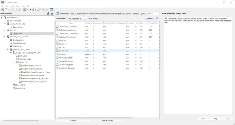
Simulink Data Dictionary is repository of data that relevant to our model. It stores details like data type, initial value, min max values, etc of all the parameters and signals that used in our model. It does not store simulation data.
CONFIGURATION PARAMETER UPDATE:
Solver settings:
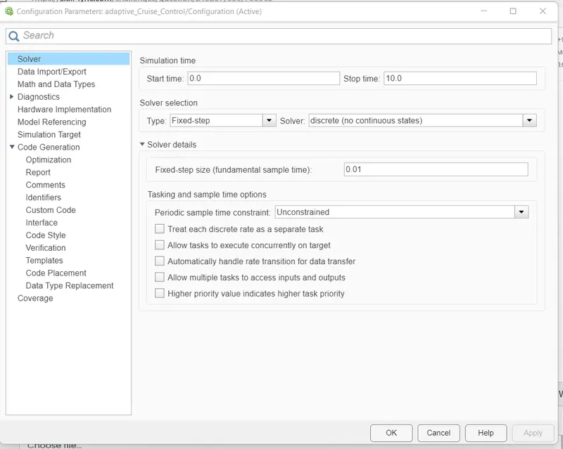
In solver settings sample time and solver types can be changed as per requirement
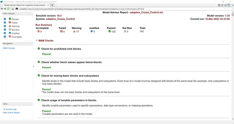
MODEL ADVISOR:
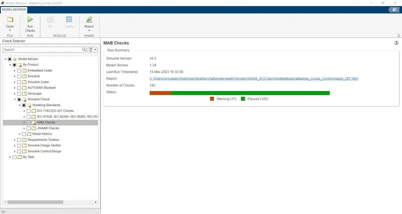
The model advisor helps to check that our model satisfy the MAB standards and guidelines. and it also checks that our model runs as per paramenter settings.
Then it generates the report, if it finds any error it suggest some changes so that we can correct it.
CODE:
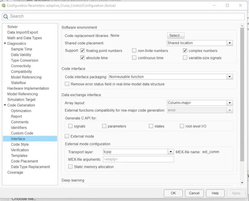
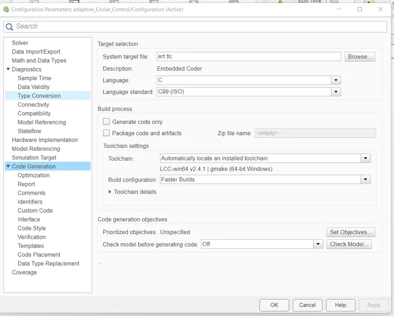
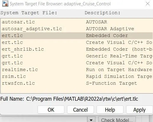
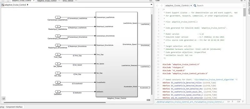
For code generation have to make some settings in configuration parameters. change the target file to ert.tlc embedded coder.
RESULT:
Thus the Adaptive Cruise Control was designed as per the given requirement. The model was running sucessfully without showing any error.