Project 2 Adaptive Cruise Control
Adaptive Cruise Control (ACC).
2. Introduction :-
Adaptive cruise control (ACC) is one of the most used and important features of autonomous driving and ADAS features ,and it is mostly used in all vehicles.
Driving in heavy traffic or keeping a safe distance to the preceding vehicle calls for a high level of concentration.
The Adaptive Cruise Control feature can reduce the stress on the driver by automatically controlling the vehicle speed & maintaining a predefined minimum distance to the preceding vehicle.
As a consequence, the driver enjoys more comfort & can concentrate on the road little better.
A radar sensor is usually at the core of the Adaptive Cruise Control,installed at the front of the vehicle, the system permanently monitors the road ahead.
As long as the road ahead is clear, cruise control feature maintains the speed set by the driver,if the system spots a slower vehicle within its detection range, it gently reduces speed by releasing the accelerator or actively engaging the brake control system.
If the vehicle ahead speeds up or changes lanes, the cruise control automatically accelerates to the driver’s desired speed.
In this way adaptive cruise control work depending on the condition of vehicle in front and road vehicle.
3. Workdone :-
Following is the matlab model for adaptive cruise control is as shown:-
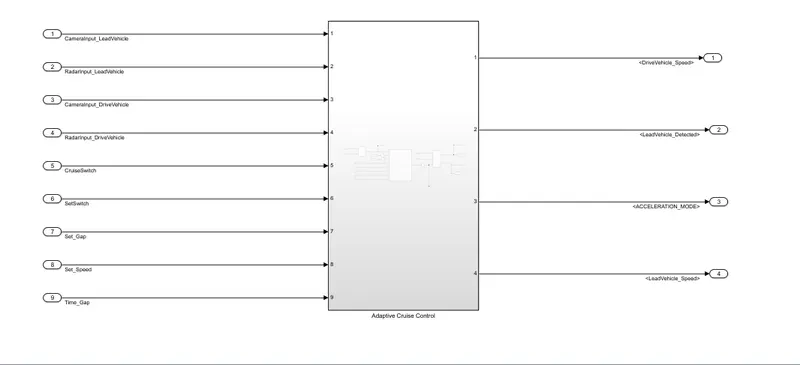
It consist of subsystem ,inside adaptive cruise control subsystem there are two subsytem one for lead vehicle and drive vehicle along with state logic for adaptive cruise control algorithm.
Inputs of "ACC" subsystem are:-
- Camerinput_leadvehicle
- Radarinput_leadvehicle
- Camerainput_drivevehicle
- Radarinput_drivevehicle
- Cruiseswitch
- SetSwitch
- Set_Gap
- Set_Speed
- Time_Gap
Output from "ACC" subsytem are :-
- DriveVehicle_Speed
- LeadVehicle_detected
- ACCELERATION_MODE
- LeadVehicle_Speed
According to requirement for lead vehicle the matlab model is as follows :-
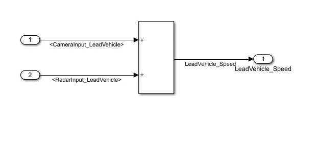
It takes the input as "camerainput_leadvehicle and radarinput_leadvehicle" after doing summation it gives output as "Leadvehicle_speed".
As per requirement for drive vehicle the matlab model is as shown :-
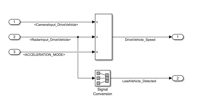
In this summation of "camerainput_drivevehicle ,radarinput_drivevehicle and ACCELERATION_MODE" as input and gives output as "Drivevehicle_speed" and other one is leadvehicle_detected it is converted from radarinput_drivevehicle using signal conversion block .
The ACC algorithms architecture is as shown ,its logic and command inside state is not possible to attached here in screenshot for that .slx file is attached to this project.
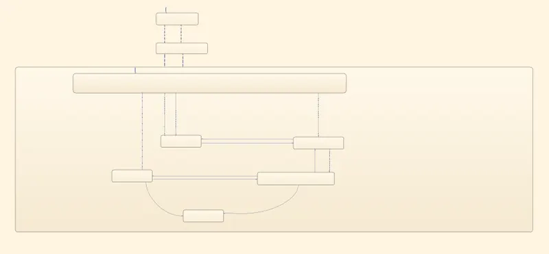
The input and output of state logic is defined in symbol pane as shown :-
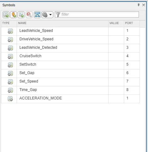
The whole model of ACC is as shown :-
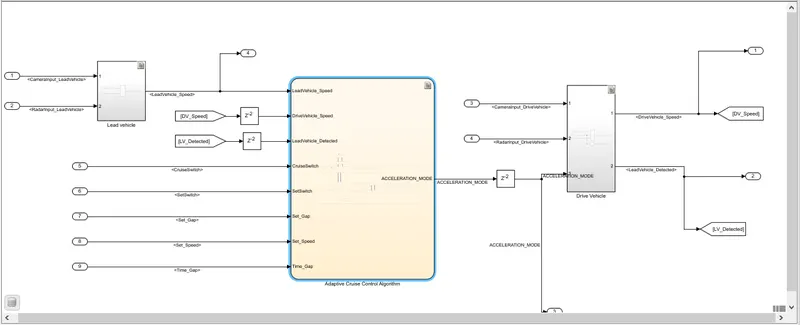
Here all subsytem inside ACC subsytem are shown along with state logic .
Depending on the camera input and radar which is installed in front of drive vehicle position of lead vehicle and drive vehicle detected .
All the inputs tota l of 9 inputs then given to ACC algorithm and depending on condition the ACC state logic gives output as it tells the state of ACC as OFF or ON or Standby.
All input and output signals are defined in SLDD file which includes its datatype,minimum and maximum value,its dimension,etc.
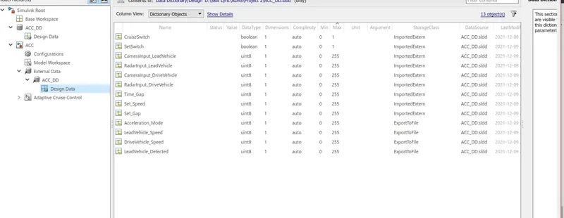
Here the input and output signals are defined which is as shown ,for input signal storage class is"Importedexterm" and output signal for output signal is"ExportTofile."
Requirement tagging is also done for each subsytem for this word file for respective tagging is atteached to this profect.
4. Conclusion :-
Comprehensive analysis of this project is done in matlab/simulink and it is successfully implimented.