Project 2 Adaptive Cruise Control
Adaptive Cruise Control
Objective of Main Project:
- To develop Adaptive Cruise Control feature as per the Requirement Document using MATLAB Simulink.
- To follow all the MBD related processes like,
- Requirement Tagging & Traceability
- SLDD creation
- Configuration Parameter changes
- Model Advisor check &
- Code Generation.
- To use Embedded Coder to generate the code.
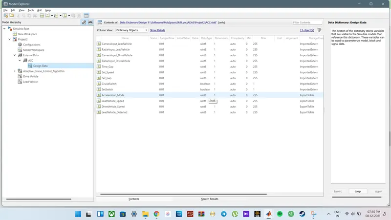
- Storage classes to be chosen as,
- For Input signals: ImportedExtern
- For Output signal: Export to File
- For local signals: localizable
- For calibration signals: Const.
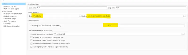
- To Choose sample time for all signals as 0.01s
Model based on Requirement
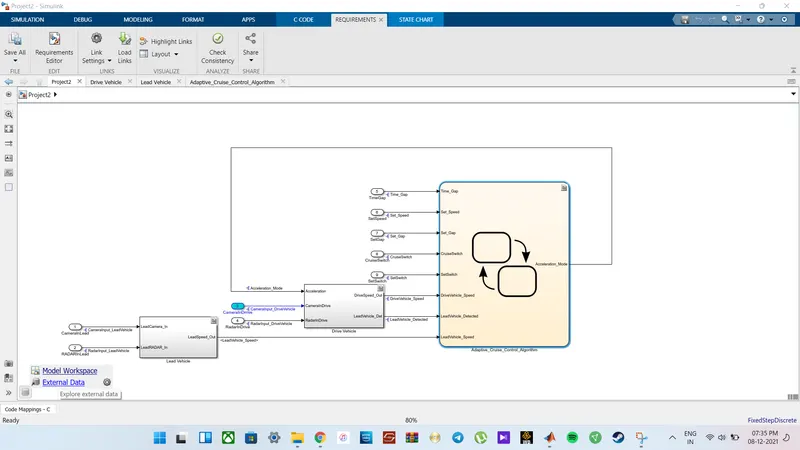
The model basically comprises of three requirements. Each requirement is carried to a particular subsystem performing its task alone.Each Subsytem contains multiple inputs and outputs as per the requirement. The model is also integrated with a feedback loop that helps the model to operate at any instant effectively.
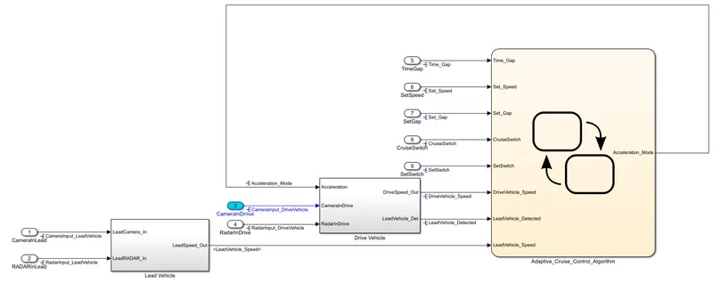
Requirement 1– Lead Vehicle:
Here, we are considering a Lead Vehicle. Lead Vehicle is a vehicle which is driving in the road ahead of our drive vehicle.
- Two input signals for Lead Vehicle are Camera Input and RADAR input.
- The Corresponding input Signal Names are: CameraInput_LeadVehicle & RadarInput_LeadVehicle.
- Ideally sensor fusion techniques will be deployed to process & analyze data from camera & radar. For complexity reasons, let’s not adapt to any such algorithms.
- We can simply add both the radar & camera inputs & the corresponding output is read as Speed profile output.
- The Corresponding output Signal Name is LeadVehicle_Speed.
- Speed data of the lead vehicle is critical in implementing the Adaptive Cruise Control algorithm.
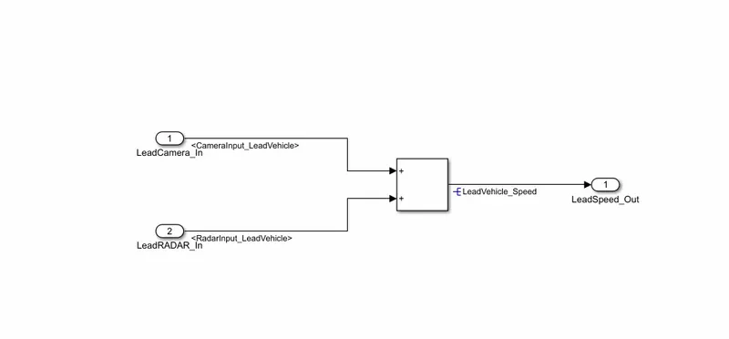
Requirement 2 – Drive Vehicle:
Here, we are considering a Drive Vehicle.Drive Vehicle is the vehicle driven by the user & this is the vehicle which has Adaptive Cruise Control algorithm in it.
- Like the Lead Vehicle, Drive Vehicle algorithm also has 2 input signals which are Camera Input and RADAR input
- The Corresponding input Signal Names are CameraInput_DriveVehicle and RadarInput_DriveVehicle
- Also we are considering a signal coming as an Input to this subsystem from the Lead Vehicle
- And the Corresponding name of that input Signal is Acceleration_Mode)
- As a result, in effective we have a total of three inputs into this requirement.
- Like the above requirement, sensor fusion techniques will also be deployed here, for complexity reasons we are ignoring them.
- Like the Lead Vehicle, Drive Vehicle algorithm also has 2 output signals which Vehicle Speed and Vehicle Detection.
- The Corresponding output Signal Names are DriveVehicle_Speed & LeadVehicle_Detected.
- Signal DriveVehicle_Speed is summation of three input signals mentioned above & LeadVehicle_Detected is renamed from Input Signal RadarInput_DriveVehicle by mere use of Signal Conversion block.
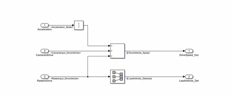
Requirement 3 – Adaptive Cruise Control Algorithm:
- In short, the Adaptive Cruise Control feature has 3 major modes of operation, whicah are;
- OFF Mode
- STANDBY Mode &
- ON Mode.
- For this particular requirement, We will have to implement it as state machine logic in Simulink.
- The corresponding input signals to this state machine system are;
- Time Gap
- Set Speed
- Set Gap
- Cruise Switch
- Set Switch
- And its corresponding Signal Names are : Time_Gap, Set_Speed, Set_Gap, CruiseSwitch, SetSwitch
- Also, the two output signals from Drive Vehicle are fed as the input for the State Flow algorithm
- Its Signal Names are: DriveVehicle_Speed & LeadVehicle_Detected which are fed from requirement-2 as an input signal into this state machine block.
- Additionally, output signal (Signal Name: LeadVehicle_Speed) from requirement-1 is given as an input signal to this state machine block as well.
- The only Output from this subsystem is a signal called Acceleration Mode which governs the vehicular speed of the drive vehicle which automatically adjusts its speed & velocity to match the lead vehicle.
- Its corresponding Signal Name is Acceleration_Mode
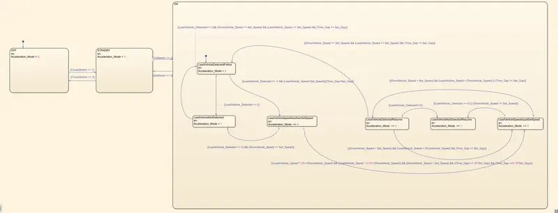
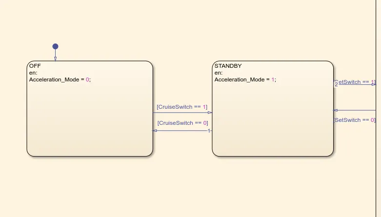
Requirement 3a – ACC OFF MODE state logic:
- This is the default state inside state machine logic. Output signal Acceleration_Mode is at value 0 in this state.
- This state is governed by input signal CruiseSwitch.
- If CruiseSwitch is equal to 1, state ACC STANDBY mode will get activated. If CruiseSwitch is equal to 0, state ACC OFF mode will get activated, from either ACC ON mode or ACC STANDBY mode
Requirement 3c (ii) – LeadVehicle_Not_Detected (ACC ON MODE):
- Output signal Acceleration_Mode is equal to 1.
- Condition to transit from LeadVehicle_Not_Detected to LeadVehicle_Detected_Follow; Input signals condition [(LeadVehicle_Detected==1) && (DriveVehicle_Speed == Set_Speed) && (LeadVehicle_Speed >= Set_Speed) && (Time_Gap >= Set_Gap)]
- Condition to transit from LeadVehicle_Not_Detected to LeadVehicle_Speed_lessthan_Set_Speed; Input signals condition [(LeadVehicle_Detected == 1) && (LeadVehicle_Speed < Set_Speed) || (Time_Gap < Set_Gap)]
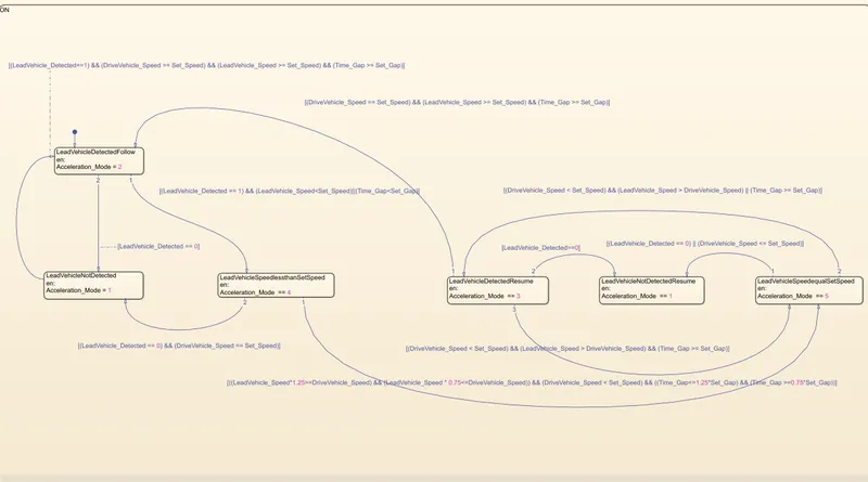
Requirement 3c – ACC ON MODE state logic:
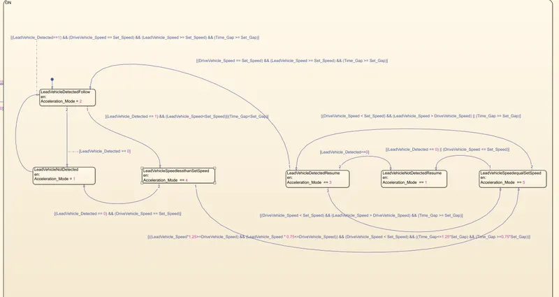
This state will be activated when input signal SetSwitch is equal to 1. There are 6 sub states to this state logic: They are:
- LeadVehicle_Detected_Follow (Default)
- LeadVehicle_Not_Detected
- LeadVehicle_Detected_Resume
- LeadVehicle_Not_Detected_Resume
- LeadVehicle_Speed_lessthan_Set_Speed
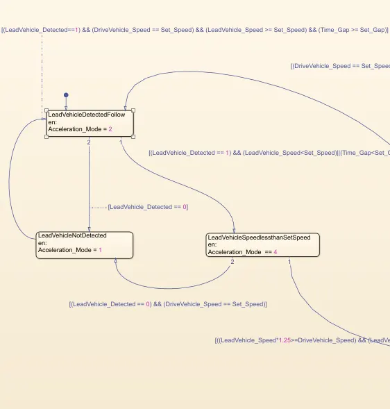
Requirement 3c (i) – LeadVehicle_Detected_Follow (ACC ON MODE):
- This is the default sub state inside ACC ON MODE state. Output signal Acceleration_Mode is equal to 2.
- Condition to transit from LeadVehicle_Detected_Follow to LeadVehicle_Not_Detected; Input signal condition LeadVehicle_Detected == 0.
- Condition to transit from LeadVehicle_Detected_Follow to LeadVehicle_Speed_lessthan_Set_Speed; Input Signals condition (LeadVehicle_Detected == 1) && (LeadVehicle_Speed < Set_Speed) || (Time_Gap < Set_Gap).
Requirement 3c (ii) – LeadVehicle_Not_Detected (ACC ON MODE):
- Output signal Acceleration_Mode is equal to 1.
- Condition to transit from LeadVehicle_Not_Detected to LeadVehicle_Detected_Follow; Input signals condition [(LeadVehicle_Detected==1) && (DriveVehicle_Speed == Set_Speed) && (LeadVehicle_Speed >= Set_Speed) && (Time_Gap >= Set_Gap)]
- Condition to transit from LeadVehicle_Not_Detected to LeadVehicle_Speed_lessthan_Set_Speed; Input signals condition [(LeadVehicle_Detected == 1) && (LeadVehicle_Speed < Set_Speed) || (Time_Gap < Set_Gap)]
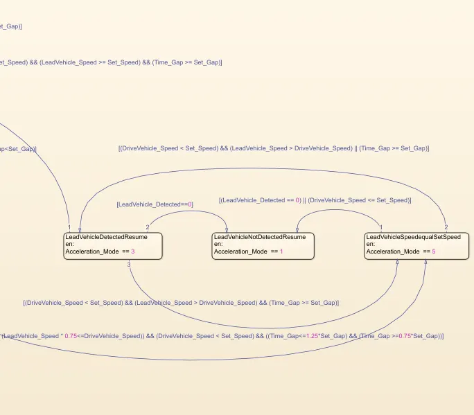
Requirement 3c (iii) – LeadVehicle_Detected_Resume (ACC ON MODE):
- Output signal Acceleration_Mode is equal to 3.
- Condition to transit from LeadVehicle_Detected_Resume to LeadVehicle_Detected_Follow; Input signals condition [(DriveVehicle_Speed == Set_Speed) && (LeadVehicle_Speed >= Set_Speed) && (Time_Gap >= Set_Gap)]
- Condition to transit from LeadVehicle_Detected_Resume to LeadVehicle_Not_Detected_Resume; Input signal condition LeadVehicle_Detected==0.
- Condition to transit from LeadVehicle_Detected_Resume to LeadVehicle_Speed_equal_Set_Speed; Input Signal condition [(DriveVehicle_Speed < Set_Speed) && (LeadVehicle_Speed > DriveVehicle_Speed) && (Time_Gap >= Set_Gap)]
Requirement 3c (iv) - LeadVehicle_Not_Detected_Resume (ACC ON MODE):
- Output signal Acceleration_Mode is equal to 1.
Requirement 3c (v) - LeadVehicle_Speed_lessthan_Set_Speed (ACC ON MODE):
- Output signal Acceleration_Mode is equal to 4.
- Condition to transit from LeadVehicle_Speed_lessthan_Set_Speed to LeadVehicle_Not_Detected; Input signal condition [(LeadVehicle_Detected == 0) && (DriveVehicle_Speed == Set_Speed)]
- Condition to transit from LeadVehicle_Speed_lessthan_Set_Speed to LeadVehicle_Speed_equal_Set_Speed; Input signals condition [((LeadVehicle_Speed*1.25>=DriveVehicle_Speed) && (LeadVehicle_Speed * 0.75<=DriveVehicle_Speed)) && (DriveVehicle_Speed < Set_Speed) && ((Time_Gap<=1.25*Set_Gap) && (Time_Gap >=0.75*Set_Gap))]
Requirement 3c (vi) - LeadVehicle_Speed_equal_Set_Speed (ACC ON MODE):
- Output signal Acceleration_Mode is equal to 5.
- Condition to transit from LeadVehicle_Speed_equal_Set_Speed to LeadVehicle_Not_Detected_Resume; Input signal conditions is [(LeadVehicle_Detected == 0) || (DriveVehicle_Speed <= Set_Speed)]
- Condition to transit from LeadVehicle_Speed_equal_Set_Speed to LeadVehicle_Detected_Resume; Input signal conditions [(DriveVehicle_Speed < Set_Speed) && (LeadVehicle_Speed > DriveVehicle_Speed) || (Time_Gap >= Set_Gap)]
- Condition to transit from LeadVehicle_Speed_equal_Set_Speed to LeadVehicle_Speed_lessthan_Set_Speed; Input signals conditions [(LeadVehicle_Speed
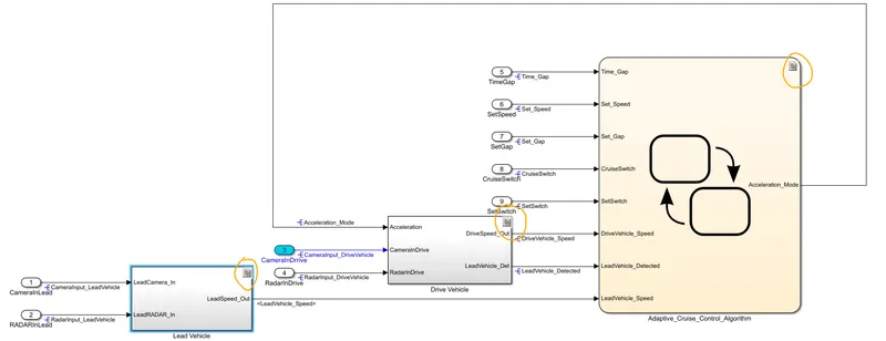
The Entire Subsystem as a MODEL:
Linking the Requirements:
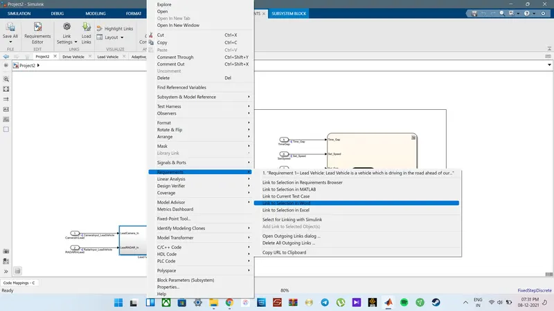
The specific requirements are already prepared and saved in word format. Each Subsytem is linked with its corresponding requirement.
For requirement tagging,
Right Click on the corresponding block, Goto Requirements, and Select the Corresponding 'Link to Selection ----' option.
Here, i have choosen Link to Selection in WORD
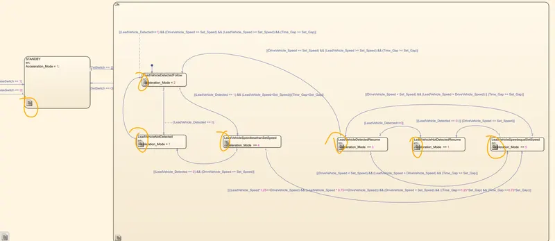
Once, the appropriate documents are attached, we can see a small 'document icon' on the right- top of each subsystem.
In order top create a DATA DICTIONARY for the Model,
Open Model Settings, Goto External Data and create new data
Once created, we can see a small 'stacked' icon on the Bottom- Left of the window.
Click on that, a small option will pop-up, among that choose External Data
Once opened the corresponding Data file, we can start entering the data requirements.
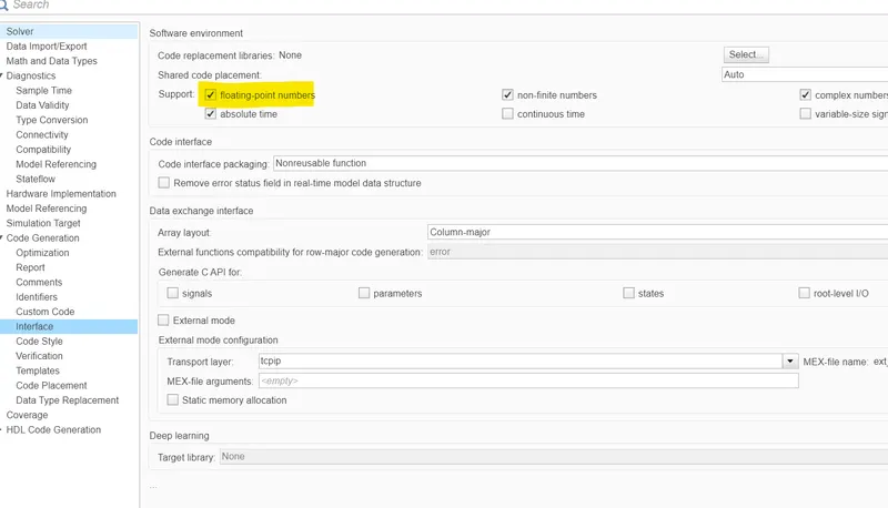
To Comply with MAAB Guidelines and to successfully complete the model advisor check, it is important to Modifying the Configuration Parameters,
To Open Config Configuration Parameter, Click on Modelling Tab, Goto Model Settings
Here, I mainly changed the Highlight parameters from Default parameters along with some other parameters, especially changing the Target File and Sample Time
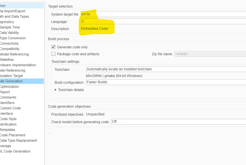
While Running the advisor check, it is important to select the MAB and JMAB guidelines along with some other guidelines
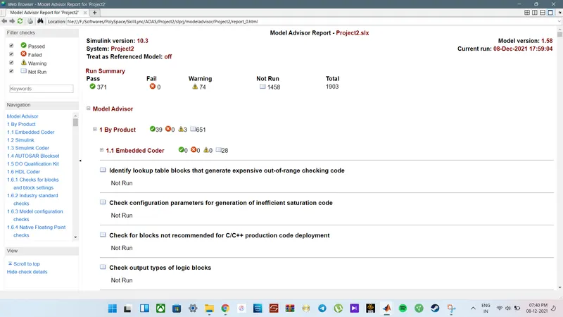
Once the Model Advisor is successfully completed without any other, you are good to go to Create Code Generation.
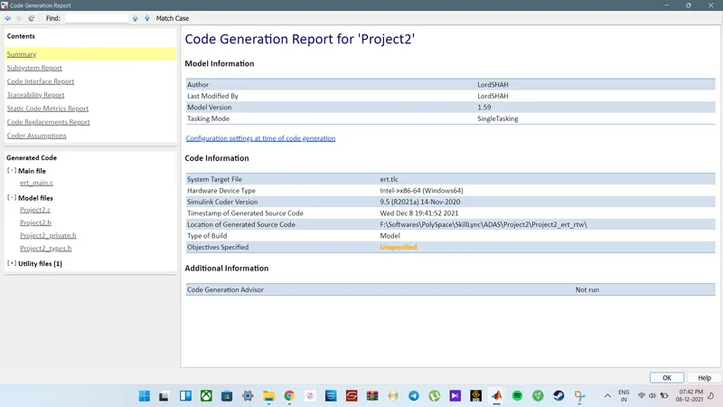
To Generate C Code, make sure to select the Embedded Coder and also to choose the Target File as ert.tlc
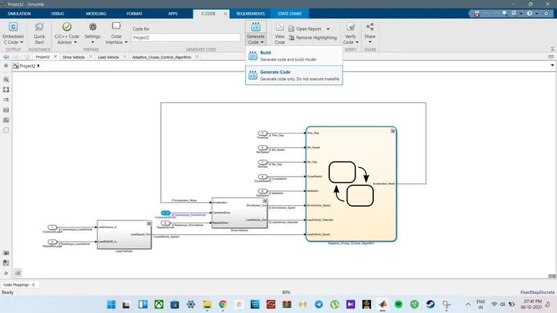
Once, the parameters are correctly entered, we can generate the C- Code by,
Clicking on Apps, Goto Embedded Coder and drop down the Generate Code option and Select Generate Code.
This will Automatically generate the C. Code, or in general, we can say, it is possible to generate C-Code using Auto-Code
Once the Code Generation is successfully completed, a pop-up window comes with the Summary of Generated Code.
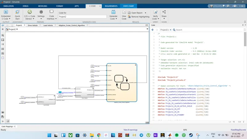
main file
ert.tlc
File: ert_main.c
1	/*
2	 * File: ert_main.c
3	 *
4	 * Code generated for Simulink model 'Project2'.
5	 *
6	 * Model version                  : 1.59
7	 * Simulink Coder version         : 9.5 (R2021a) 14-Nov-2020
8	 * C/C++ source code generated on : Wed Dec  8 19:41:52 2021
9	 *
10	 * Target selection: ert.tlc
11	 * Embedded hardware selection: Intel->x86-64 (Windows64)
12	 * Code generation objectives: Unspecified
13	 * Validation result: Not run
14	 */
15
16	#include
17	#include               /* This ert_main.c example uses printf/fflush */
18	#include "Project2.h"                  /* Model's header file */
19	#include "rtwtypes.h"
20
21	/*
22	 * Associating rt_OneStep with a real-time clock or interrupt service routine
23	 * is what makes the generated code "real-time".  The function rt_OneStep is
24	 * always associated with the base rate of the model.  Subrates are managed
25	 * by the base rate from inside the generated code.  Enabling/disabling
26	 * interrupts and floating point context switches are target specific.  This
27	 * example code indicates where these should take place relative to executing
28	 * the generated code step function.  Overrun behavior should be tailored to
29	 * your application needs.  This example simply sets an error status in the
30	 * real-time model and returns from rt_OneStep.
31	 */
32	void rt_OneStep(void);
33	void rt_OneStep(void)
34	{
35	  static boolean_T OverrunFlag = false;
36
37	  /* Disable interrupts here */
38
39	  /* Check for overrun */
40	  if (OverrunFlag) {
41	    rtmSetErrorStatus(Project2_M, "Overrun");
42	    return;
43	  }
44
45	  OverrunFlag = true;
46
47	  /* Save FPU context here (if necessary) */
48	  /* Re-enable timer or interrupt here */
49	  /* Set model inputs here */
50
51	  /* Step the model */
52	  Project2_step();
53
54	  /* Get model outputs here */
55
56	  /* Indicate task complete */
57	  OverrunFlag = false;
58
59	  /* Disable interrupts here */
60	  /* Restore FPU context here (if necessary) */
61	  /* Enable interrupts here */
62	}
63
64	/*
65	 * The example "main" function illustrates what is required by your
66	 * application code to initialize, execute, and terminate the generated code.
67	 * Attaching rt_OneStep to a real-time clock is target specific.  This example
68	 * illustrates how you do this relative to initializing the model.
69	 */
70	int_T main(int_T argc, const char *argv[])
71	{
72	  /* Unused arguments */
73	  (void)(argc);
74	  (void)(argv);
75
76	  /* Initialize model */
77	  Project2_initialize();
78
79	  /* Attach rt_OneStep to a timer or interrupt service routine with
80	   * period 0.01 seconds (the model's base sample time) here.  The
81	   * call syntax for rt_OneStep is
82	   *
83	   *  rt_OneStep();
84	   */
85	  printf("Warning: The simulation will run forever. "
86	         "Generated ERT main won't simulate model step behavior. "
87	         "To change this behavior select the 'MAT-file logging' option.\n");
88	  fflush((NULL));
89	  while (rtmGetErrorStatus(Project2_M) == (NULL)) {
90	    /*  Perform other application tasks here */
91	  }
92
93	  /* Disable rt_OneStep() here */
94
95	  /* Terminate model */
96	  Project2_terminate();
97	  return 0;
98	}
99
100	/*
101	 * File trailer for generated code.
102	 *
103	 * [EOF]
104	 */
105
Model files
- Project2.c
File: Project2.c 1 /* 2 * File: Project2.c 3 * 4 * Code generated for Simulink model 'Project2'. 5 * 6 * Model version : 1.59 7 * Simulink Coder version : 9.5 (R2021a) 14-Nov-2020 8 * C/C++ source code generated on : Wed Dec 8 19:41:52 2021 9 * 10 * Target selection: ert.tlc 11 * Embedded hardware selection: Intel->x86-64 (Windows64) 12 * Code generation objectives: Unspecified 13 * Validation result: Not run 14 */ 15 16 #include "Project2.h" 17 #include "Project2_private.h" 18 19 /* Named constants for Chart: '/Adaptive_Cruise_Control_Algorithm' */ 20 #define IN_LeadVehicleNotDetectedResume ((uint8_T)4U) 21 #define IN_LeadVehicleSpeedequalSetSpee ((uint8_T)5U) 22 #define IN_LeadVehicleSpeedlessthanSetS ((uint8_T)6U) 23 #define Pr_IN_LeadVehicleDetectedFollow ((uint8_T)1U) 24 #define Pr_IN_LeadVehicleDetectedResume ((uint8_T)2U) 25 #define Proje_IN_LeadVehicleNotDetected ((uint8_T)3U) 26 #define Project2_IN_NO_ACTIVE_CHILD ((uint8_T)0U) 27 #define Project2_IN_OFF ((uint8_T)1U) 28 #define Project2_IN_ON ((uint8_T)2U) 29 #define Project2_IN_STANDBY ((uint8_T)3U) 30 31 /* Exported data definition */ 32 33 /* Definition for custom storage class: ExportToFile */ 34 uint8_T Acceleration_Mode; /* '/Adaptive_Cruise_Control_Algorithm' */ 35 uint8_T DriveVehicle_Speed; /* '/Add' */ 36 uint8_T LeadVehicle_Detected; /* '/Signal Conversion' */ 37 uint8_T LeadVehicle_Speed; /* '/Add' */ 38 39 /* Block states (default storage) */ 40 DW_Project2_T Project2_DW; 41 42 /* Real-time model */ 43 static RT_MODEL_Project2_T Project2_M_; 44 RT_MODEL_Project2_T *const Project2_M = &Project2_M_; 45 46 /* Model step function */ 47 void Project2_step(void) 48 { 49 /* Sum: '/Add' incorporates: 50 * Inport: '/CameraInDrrive' 51 * Inport: '/RadarInDrive' 52 * UnitDelay: '/Unit Delay' 53 */ 54 DriveVehicle_Speed = (uint8_T)((uint32_T)(uint8_T)((uint32_T)Acceleration_Mode 55 + CameraInput_DriveVehicle) + RadarInput_DriveVehicle); 56 57 /* SignalConversion: '/Signal Conversion' incorporates: 58 * Inport: '/RadarInDrive' 59 */ 60 LeadVehicle_Detected = RadarInput_DriveVehicle; 61 62 /* Sum: '/Add' incorporates: 63 * Inport: '/CameraInLead' 64 * Inport: '/RADARInLead' 65 */ 66 LeadVehicle_Speed = (uint8_T)((uint32_T)CameraInput_LeadVehicle + 67 RadarInput_LeadVehicle); 68 69 /* Chart: '/Adaptive_Cruise_Control_Algorithm' incorporates: 70 * Inport: '/CruiseSwitch' 71 * Inport: '/SetGap' 72 * Inport: '/SetSpeed' 73 * Inport: '/SetSwitch' 74 * Inport: '/TimeGap' 75 */ 76 if (Project2_DW.is_active_c3_Project2 == 0U) { 77 Project2_DW.is_active_c3_Project2 = 1U; 78 Project2_DW.is_c3_Project2 = Project2_IN_OFF; 79 Acceleration_Mode = 0U; 80 } else { 81 switch (Project2_DW.is_c3_Project2) { 82 case Project2_IN_OFF: 83 if (CruiseSwitch) { 84 Project2_DW.is_c3_Project2 = Project2_IN_STANDBY; 85 Acceleration_Mode = 1U; 86 } 87 break; 88 89 case Project2_IN_ON: 90 if (!SetSwitch) { 91 Project2_DW.is_ON = Project2_IN_NO_ACTIVE_CHILD; 92 Project2_DW.is_c3_Project2 = Project2_IN_STANDBY; 93 Acceleration_Mode = 1U; 94 } else { 95 switch (Project2_DW.is_ON) { 96 case Pr_IN_LeadVehicleDetectedFollow: 97 if (((LeadVehicle_Detected == 1) && (LeadVehicle_Speed < Set_Speed)) || 98 (Time_Gap < Set_Gap)) { 99 Project2_DW.is_ON = IN_LeadVehicleSpeedlessthanSetS; 100 } else if (LeadVehicle_Detected == 0) { 101 Project2_DW.is_ON = Proje_IN_LeadVehicleNotDetected; 102 Acceleration_Mode = 1U; 103 } 104 break; 105 106 case Pr_IN_LeadVehicleDetectedResume: 107 if ((DriveVehicle_Speed == Set_Speed) && (LeadVehicle_Speed >= 108 Set_Speed) && (Time_Gap >= Set_Gap)) { 109 Project2_DW.is_ON = Pr_IN_LeadVehicleDetectedFollow; 110 Acceleration_Mode = 2U; 111 } else if (LeadVehicle_Detected == 0) { 112 Project2_DW.is_ON = IN_LeadVehicleNotDetectedResume; 113 } else if ((DriveVehicle_Speed < Set_Speed) && (LeadVehicle_Speed > 114 DriveVehicle_Speed) && (Time_Gap >= Set_Gap)) { 115 Project2_DW.is_ON = IN_LeadVehicleSpeedequalSetSpee; 116 } 117 break; 118 119 case Proje_IN_LeadVehicleNotDetected: 120 if ((LeadVehicle_Detected == 1) && (DriveVehicle_Speed == Set_Speed) && 121 (LeadVehicle_Speed >= Set_Speed) && (Time_Gap >= Set_Gap)) { 122 Project2_DW.is_ON = Pr_IN_LeadVehicleDetectedFollow; 123 Acceleration_Mode = 2U; 124 } 125 break; 126 127 case IN_LeadVehicleNotDetectedResume: 128 break; 129 130 case IN_LeadVehicleSpeedequalSetSpee: 131 if ((LeadVehicle_Detected == 0) || (DriveVehicle_Speed <= Set_Speed)) 132 { 133 Project2_DW.is_ON = IN_LeadVehicleNotDetectedResume; 134 } else if (((DriveVehicle_Speed < Set_Speed) && (LeadVehicle_Speed > 135 DriveVehicle_Speed)) || (Time_Gap >= Set_Gap)) { 136 Project2_DW.is_ON = Pr_IN_LeadVehicleDetectedResume; 137 } 138 break; 139 140 default: 141 /* case IN_LeadVehicleSpeedlessthanSetSpeed: */ 142 if (((real_T)LeadVehicle_Speed * 1.25 >= DriveVehicle_Speed) && 143 ((real_T)LeadVehicle_Speed * 0.75 <= DriveVehicle_Speed) && 144 (DriveVehicle_Speed < Set_Speed) && ((Time_Gap <= 1.25 * (real_T) 145 Set_Gap) && (Time_Gap >= 0.75 * (real_T)Set_Gap))) { 146 Project2_DW.is_ON = IN_LeadVehicleSpeedequalSetSpee; 147 } else if ((LeadVehicle_Detected == 0) && (DriveVehicle_Speed == 148 Set_Speed)) { 149 Project2_DW.is_ON = Proje_IN_LeadVehicleNotDetected; 150 Acceleration_Mode = 1U; 151 } 152 break; 153 } 154 } 155 break; 156 157 default: 158 /* case IN_STANDBY: */ 159 if (!CruiseSwitch) { 160 Project2_DW.is_c3_Project2 = Project2_IN_OFF; 161 Acceleration_Mode = 0U; 162 } else if (SetSwitch) { 163 Project2_DW.is_c3_Project2 = Project2_IN_ON; 164 Project2_DW.is_ON = Pr_IN_LeadVehicleDetectedFollow; 165 Acceleration_Mode = 2U; 166 } 167 break; 168 } 169 } 170 171 /* End of Chart: '/Adaptive_Cruise_Control_Algorithm' */ 172 } 173 174 /* Model initialize function */ 175 void Project2_initialize(void) 176 { 177 /* (no initialization code required) */ 178 } 179 180 /* Model terminate function */ 181 void Project2_terminate(void) 182 { 183 /* (no terminate code required) */ 184 } 185 186 /* 187 * File trailer for generated code. 188 * 189 * [EOF] 190 */ 191 - Project2.c
File: Project2.h 1 /* 2 * File: Project2.h 3 * 4 * Code generated for Simulink model 'Project2'. 5 * 6 * Model version : 1.59 7 * Simulink Coder version : 9.5 (R2021a) 14-Nov-2020 8 * C/C++ source code generated on : Wed Dec 8 19:41:52 2021 9 * 10 * Target selection: ert.tlc 11 * Embedded hardware selection: Intel->x86-64 (Windows64) 12 * Code generation objectives: Unspecified 13 * Validation result: Not run 14 */ 15 16 #ifndef RTW_HEADER_Project2_h_ 17 #define RTW_HEADER_Project2_h_ 18 #ifndef Project2_COMMON_INCLUDES_ 19 #define Project2_COMMON_INCLUDES_ 20 #include "rtwtypes.h" 21 #endif /* Project2_COMMON_INCLUDES_ */ 22 23 #include "Project2_types.h" 24 25 /* Macros for accessing real-time model data structure */ 26 #ifndef rtmGetErrorStatus 27 #define rtmGetErrorStatus(rtm) ((rtm)->errorStatus) 28 #endif 29 30 #ifndef rtmSetErrorStatus 31 #define rtmSetErrorStatus(rtm, val) ((rtm)->errorStatus = (val)) 32 #endif 33 34 /* Block states (default storage) for system '' */ 35 typedef struct { 36 uint8_T is_active_c3_Project2;/* '/Adaptive_Cruise_Control_Algorithm' */ 37 uint8_T is_c3_Project2; /* '/Adaptive_Cruise_Control_Algorithm' */ 38 uint8_T is_ON; /* '/Adaptive_Cruise_Control_Algorithm' */ 39 } DW_Project2_T; 40 41 /* Real-time Model Data Structure */ 42 struct tag_RTM_Project2_T { 43 const char_T * volatile errorStatus; 44 }; 45 46 /* Block states (default storage) */ 47 extern DW_Project2_T Project2_DW; 48 49 /* Model entry point functions */ 50 extern void Project2_initialize(void); 51 extern void Project2_step(void); 52 extern void Project2_terminate(void); 53 54 /* Exported data declaration */ 55 56 /* Declaration for custom storage class: ExportToFile */ 57 extern uint8_T Acceleration_Mode; 58 /* '/Adaptive_Cruise_Control_Algorithm' */ 59 extern uint8_T DriveVehicle_Speed; /* '/Add' */ 60 extern uint8_T LeadVehicle_Detected; /* '/Signal Conversion' */ 61 extern uint8_T LeadVehicle_Speed; /* '/Add' */ 62 63 /* Real-time Model object */ 64 extern RT_MODEL_Project2_T *const Project2_M; 65 66 /*- 67 * The generated code includes comments that allow you to trace directly 68 * back to the appropriate location in the model. The basic format 69 * is /block_name, where system is the system number (uniquely 70 * assigned by Simulink) and block_name is the name of the block. 71 * 72 * Use the MATLAB hilite_system command to trace the generated code back 73 * to the model. For example, 74 * 75 * hilite_system('') - opens system 3 76 * hilite_system('/Kp') - opens and selects block Kp which resides in S3 77 * 78 * Here is the system hierarchy for this model 79 * 80 * '' : 'Project2' 81 * '' : 'Project2/Adaptive_Cruise_Control_Algorithm' 82 * '' : 'Project2/Drive Vehicle' 83 * '' : 'Project2/Lead Vehicle' 84 */ 85 #endif /* RTW_HEADER_Project2_h_ */ 86 87 /* 88 * File trailer for generated code. 89 * 90 * [EOF] 91 */ 92 - Project2_private.h
File: Project2_private.h 1 /* 2 * File: Project2_private.h 3 * 4 * Code generated for Simulink model 'Project2'. 5 * 6 * Model version : 1.59 7 * Simulink Coder version : 9.5 (R2021a) 14-Nov-2020 8 * C/C++ source code generated on : Wed Dec 8 19:41:52 2021 9 * 10 * Target selection: ert.tlc 11 * Embedded hardware selection: Intel->x86-64 (Windows64) 12 * Code generation objectives: Unspecified 13 * Validation result: Not run 14 */ 15 16 #ifndef RTW_HEADER_Project2_private_h_ 17 #define RTW_HEADER_Project2_private_h_ 18 #include "rtwtypes.h" 19 20 /* Imported (extern) block signals */ 21 extern uint8_T CameraInput_LeadVehicle;/* '/CameraInLead' */ 22 extern uint8_T RadarInput_LeadVehicle; /* '/RADARInLead' */ 23 extern uint8_T CameraInput_DriveVehicle;/* '/CameraInDrrive' */ 24 extern uint8_T RadarInput_DriveVehicle;/* '/RadarInDrive' */ 25 extern uint8_T Time_Gap; /* '/TimeGap' */ 26 extern uint8_T Set_Speed; /* '/SetSpeed' */ 27 extern uint8_T Set_Gap; /* '/SetGap' */ 28 extern boolean_T CruiseSwitch; /* '/CruiseSwitch' */ 29 extern boolean_T SetSwitch; /* '/SetSwitch' */ 30 31 #endif /* RTW_HEADER_Project2_private_h_ */ 32 33 /* 34 * File trailer for generated code. 35 * 36 * [EOF] 37 */ 38 - Project2_types.h
File: Project2_types.h 1 /* 2 * File: Project2_types.h 3 * 4 * Code generated for Simulink model 'Project2'. 5 * 6 * Model version : 1.59 7 * Simulink Coder version : 9.5 (R2021a) 14-Nov-2020 8 * C/C++ source code generated on : Wed Dec 8 19:41:52 2021 9 * 10 * Target selection: ert.tlc 11 * Embedded hardware selection: Intel->x86-64 (Windows64) 12 * Code generation objectives: Unspecified 13 * Validation result: Not run 14 */ 15 16 #ifndef RTW_HEADER_Project2_types_h_ 17 #define RTW_HEADER_Project2_types_h_ 18 19 /* Model Code Variants */ 20 21 /* Forward declaration for rtModel */ 22 typedef struct tag_RTM_Project2_T RT_MODEL_Project2_T; 23 24 #endif /* RTW_HEADER_Project2_types_h_ */ 25 26 /* 27 * File trailer for generated code. 28 * 29 * [EOF] 30 */ 31 - rtwtypes.h
File: rtwtypes.h
1	/*
2	 * File: rtwtypes.h
3	 *
4	 * Code generated for Simulink model 'Project2'.
5	 *
6	 * Model version                  : 1.59
7	 * Simulink Coder version         : 9.5 (R2021a) 14-Nov-2020
8	 * C/C++ source code generated on : Wed Dec  8 19:41:52 2021
9	 *
10	 * Target selection: ert.tlc
11	 * Embedded hardware selection: Intel->x86-64 (Windows64)
12	 * Code generation objectives: Unspecified
13	 * Validation result: Not run
14	 */
15
16	#ifndef RTWTYPES_H
17	#define RTWTYPES_H
18
19	/* Logical type definitions */
20	#if (!defined(__cplusplus))
21	#ifndef false
22	#define false                          (0U)
23	#endif
24
25	#ifndef true
26	#define true                           (1U)
27	#endif
28	#endif
29
30	/*=======================================================================*
31	 * Target hardware information
32	 *   Device type: Intel->x86-64 (Windows64)
33	 *   Number of bits:     char:   8    short:   16    int:  32
34	 *                       long:  32
35	 *                       native word size:  64
36	 *   Byte ordering: LittleEndian
37	 *   Signed integer division rounds to: Zero
38	 *   Shift right on a signed integer as arithmetic shift: on
39	 *=======================================================================*/
40
41	/*=======================================================================*
42	 * Fixed width word size data types:                                     *
43	 *   int8_T, int16_T, int32_T     - signed 8, 16, or 32 bit integers     *
44	 *   uint8_T, uint16_T, uint32_T  - unsigned 8, 16, or 32 bit integers   *
45	 *   real32_T, real64_T           - 32 and 64 bit floating point numbers *
46	 *=======================================================================*/
47	typedef signed char int8_T;
48	typedef unsigned char uint8_T;
49	typedef short int16_T;
50	typedef unsigned short uint16_T;
51	typedef int int32_T;
52	typedef unsigned int uint32_T;
53	typedef float real32_T;
54	typedef double real64_T;
55
56	/*===========================================================================*
57	 * Generic type definitions: boolean_T, char_T, byte_T, int_T, uint_T,       *
58	 *                           real_T, time_T, ulong_T.                        *
59	 *===========================================================================*/
60	typedef double real_T;
61	typedef double time_T;
62	typedef unsigned char boolean_T;
63	typedef int int_T;
64	typedef unsigned int uint_T;
65	typedef unsigned long ulong_T;
66	typedef char char_T;
67	typedef unsigned char uchar_T;
68	typedef char_T byte_T;
69
70	/*===========================================================================*
71	 * Complex number type definitions                                           *
72	 *===========================================================================*/
73	#define CREAL_T
74
75	typedef struct {
76	  real32_T re;
77	  real32_T im;
78	} creal32_T;
79
80	typedef struct {
81	  real64_T re;
82	  real64_T im;
83	} creal64_T;
84
85	typedef struct {
86	  real_T re;
87	  real_T im;
88	} creal_T;
89
90	#define CINT8_T
91
92	typedef struct {
93	  int8_T re;
94	  int8_T im;
95	} cint8_T;
96
97	#define CUINT8_T
98
99	typedef struct {
100	  uint8_T re;
101	  uint8_T im;
102	} cuint8_T;
103
104	#define CINT16_T
105
106	typedef struct {
107	  int16_T re;
108	  int16_T im;
109	} cint16_T;
110
111	#define CUINT16_T
112
113	typedef struct {
114	  uint16_T re;
115	  uint16_T im;
116	} cuint16_T;
117
118	#define CINT32_T
119
120	typedef struct {
121	  int32_T re;
122	  int32_T im;
123	} cint32_T;
124
125	#define CUINT32_T
126
127	typedef struct {
128	  uint32_T re;
129	  uint32_T im;
130	} cuint32_T;
131
132	/*=======================================================================*
133	 * Min and Max:                                                          *
134	 *   int8_T, int16_T, int32_T     - signed 8, 16, or 32 bit integers     *
135	 *   uint8_T, uint16_T, uint32_T  - unsigned 8, 16, or 32 bit integers   *
136	 *=======================================================================*/
137	#define MAX_int8_T                     ((int8_T)(127))
138	#define MIN_int8_T                     ((int8_T)(-128))
139	#define MAX_uint8_T                    ((uint8_T)(255U))
140	#define MAX_int16_T                    ((int16_T)(32767))
141	#define MIN_int16_T                    ((int16_T)(-32768))
142	#define MAX_uint16_T                   ((uint16_T)(65535U))
143	#define MAX_int32_T                    ((int32_T)(2147483647))
144	#define MIN_int32_T                    ((int32_T)(-2147483647-1))
145	#define MAX_uint32_T                   ((uint32_T)(0xFFFFFFFFU))
146
147	/* Block D-Work pointer type */
148	typedef void * pointer_T;
149
150	#endif                                 /* RTWTYPES_H */
151
152	/*
153	 * File trailer for generated code.
154	 *
155	 * [EOF]
156	 */
157
RESULT:
- Developed the Adaptive Cruise Control using MATLAB Simulink according to the Requirement Document .
- All the required instructions are followed while developing the model
- Successfully completed each of the Model Based Development related processes
- Processes like Requirement Tagging & Traceability, SLDD creation, Configuration Parameter changes, Model Advisor check & Code Generation is properly implemented.
- While generating C- Code, Embedded Coder is used and ert.tlc is used as the target file to generate the code.
- Also, while code generation, Storage class for Input signals, Output signals, Local signals and calibration signals are provided according to the requirement only.
- The entire model is designed and developed by choosing a sample time of 0.01s including all the signals.