Project 2 Adaptive Cruise Control
Aim:-
to verify
- Developing Adaptive Cruise Control feature as per the Requirement Document using MATLAB Simulink.
- Follow all of the MBD-related processes: Requirement Tagging & Traceability, SLDD creation, Configuration Parameter changes, Model Advisor check & Code Generation.
- Use Embedded Coder to generate the code. If choosing code generation, the Storage class for Input signals
- To generate the model using the given command and then generate the Code using those steps.
Process
step1
We need to prepare the SLDD fine with the given parameter as we had done using those Data.
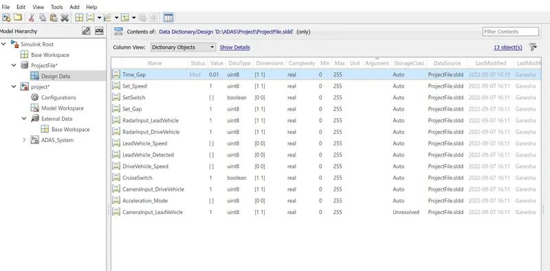
Step2:-Model preparation
In the below, we had created the model and as shown below it had 3 sub subsystems.
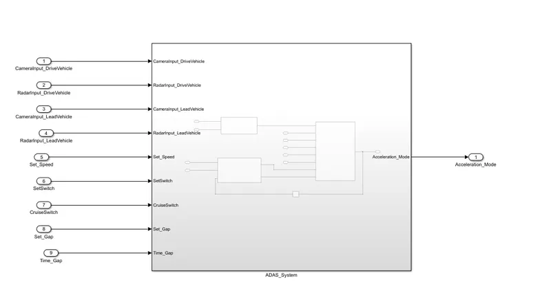
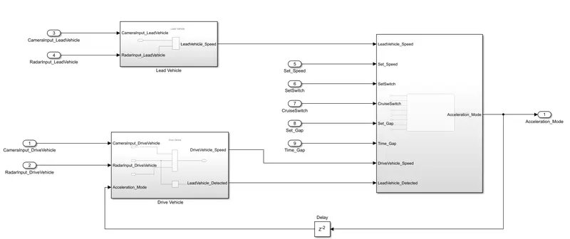
Now it has 3 subsystems and they are
1)Lead vehicle
2)Drive System
3) Sub-system chart
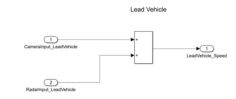
Lead Vehicle:-
here we need to get 2 systems and we got the 2 inputs then we will be getting data in form of unit 8 data we will be getting. So we will be getting data in form of boolean algebraic data then we will be converting that into summing data and both of and output we are taking and then we will give that as LeadVehicle_speed.
Drive Vehicle:-
here we have 3 input and 1 output
Camerainput_drive vehicle this in sensor will be there and we going to change the data type
RadarInput_driveVehicle is a sensor which will be getting the value then we will be changing
we have another Sign Conversion will be taking and we had connected it to LeadVehicle _dected and here we will be getting in the form of 1 for zero. zero means we won't get 1 means we had got the Vehicle. After signal Conversion, this will create a virtual bus.
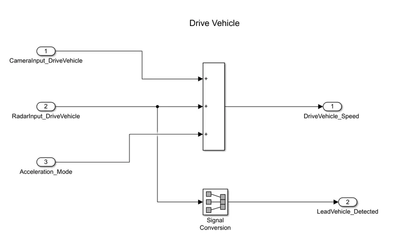
Chart of signal flow
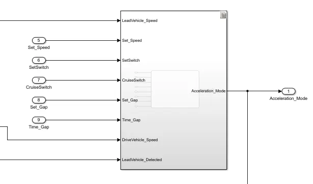
Now within this, we need to create a flow graph and we had got the 3 States those are
ACC_On
ACC_OFF
ACC_standyBY
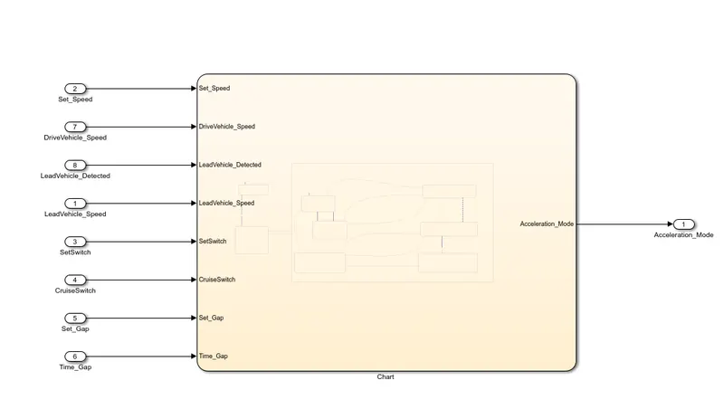
here transmission happens basis of 1 command that is curses command
now this happen once if cursor _ship will be 1 or 0 command
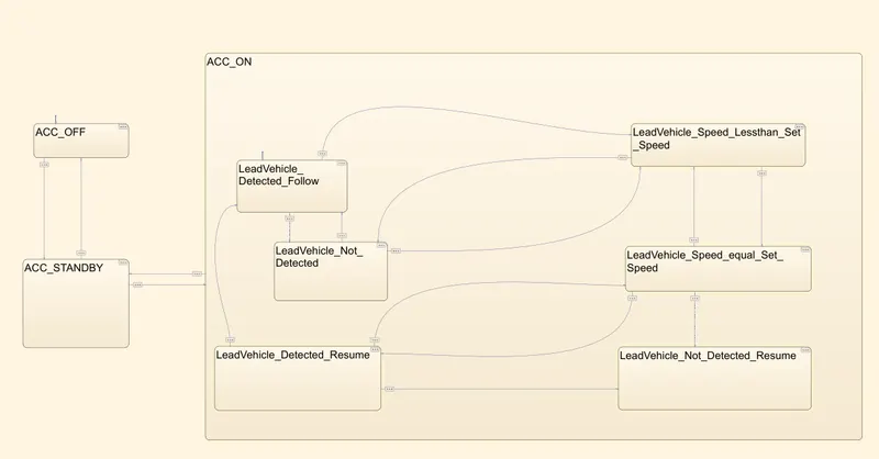
here we have lof of states in ACC_on those are
- LeadVehicle_Detected_Follow (Default)
- LeadVehicle_Not_Detected
- LeadVehicle_Detected_Resume
- LeadVehicle_Not_Detected_Resume
- LeadVehicle_Speed_lessthan_Set_Speed
- LeadVehicle_Speed_equal_Set_Speed
Now here all of these stated will be as per acceleration command and transition happen as given in the question.
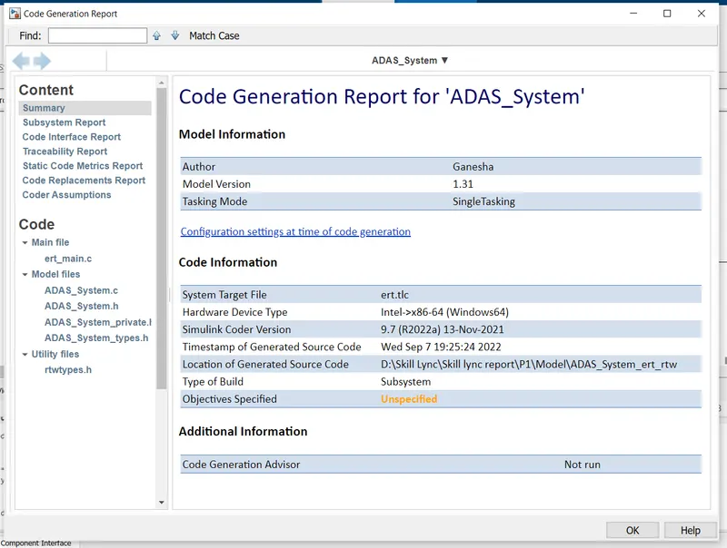
Step 4 Code Generation:
here after all of your models you need to create the code so for that we need to select the model then after selecting the model we need to go for the model generation part then it is visible to and right screen we can see that code.
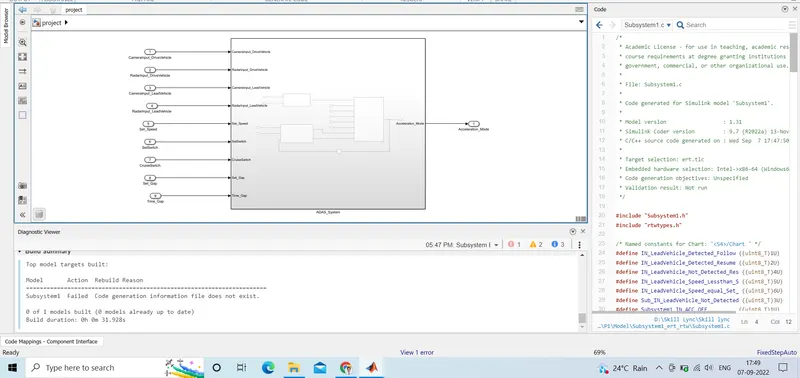
Below is the model which we had taken from model
/*
 * Academic License - for use in teaching, academic research, and meeting
 * course requirements at degree granting institutions only.  Not for
 * government, commercial, or other organizational use.
 *
 * File: Subsystem1.c
 *
 * Code generated for Simulink model 'Subsystem1'.
 *
 * Model version                  : 1.31
 * Simulink Coder version         : 9.7 (R2022a) 13-Nov-2021
 * C/C++ source code generated on : Wed Sep  7 17:47:50 2022
 *
 * Target selection: ert.tlc
 * Embedded hardware selection: Intel->x86-64 (Windows64)
 * Code generation objectives: Unspecified
 * Validation result: Not run
 */

#include "Subsystem1.h"
#include "rtwtypes.h"

/* Named constants for Chart: '/Chart ' */
#define IN_LeadVehicle_Detected_Follow ((uint8_T)1U)
#define IN_LeadVehicle_Detected_Resume ((uint8_T)2U)
#define IN_LeadVehicle_Not_Detected_Res ((uint8_T)4U)
#define IN_LeadVehicle_Speed_Lessthan_S ((uint8_T)5U)
#define IN_LeadVehicle_Speed_equal_Set_ ((uint8_T)6U)
#define Sub_IN_LeadVehicle_Not_Detected ((uint8_T)3U)
#define Subsystem1_IN_ACC_OFF          ((uint8_T)1U)
#define Subsystem1_IN_ACC_ON           ((uint8_T)2U)
#define Subsystem1_IN_ACC_STANDBY      ((uint8_T)3U)
#define Subsystem1_IN_NO_ACTIVE_CHILD  ((uint8_T)0U)

/* Block states (default storage) */
DW_Subsystem1_T Subsystem1_DW;

/* External inputs (root inport signals with default storage) */
ExtU_Subsystem1_T Subsystem1_U;

/* External outputs (root outports fed by signals with default storage) */
ExtY_Subsystem1_T Subsystem1_Y;

/* Real-time model */
static RT_MODEL_Subsystem1_T Subsystem1_M_;
RT_MODEL_Subsystem1_T *const Subsystem1_M = &Subsystem1_M_;

/* Model step function */
void Subsystem1_step(void)
{
  real_T rtb_Add;
  real_T rtb_Add_f;

  /* Sum: '/Add' incorporates:
   *  Delay: '/Delay'
   *  Inport: '/CameraInput_DriveVehicle'
   *  Inport: '/RadarInput_DriveVehicle'
   */
  rtb_Add = (Subsystem1_U.CameraInput_DriveVehicle +
             Subsystem1_U.RadarInput_DriveVehicle) + Subsystem1_DW.Delay_DSTATE
    [0];

  /* Sum: '/Add' incorporates:
   *  Inport: '/CameraInput_LeadVehicle'
   *  Inport: '/RadarInput_LeadVehicle'
   */
  rtb_Add_f = Subsystem1_U.CameraInput_LeadVehicle +
    Subsystem1_U.RadarInput_LeadVehicle;

  /* Chart: '/Chart ' incorporates:
   *  Inport: '/CruiseSwitch'
   *  Inport: '/RadarInput_DriveVehicle'
   *  Inport: '/SetSwitch'
   *  Inport: '/Set_Gap'
   *  Inport: '/Set_Speed'
   *  Inport: '/Time_Gap'
   */
  if (Subsystem1_DW.is_active_c3_Subsystem1 == 0U) {
    Subsystem1_DW.is_active_c3_Subsystem1 = 1U;
    Subsystem1_DW.is_c3_Subsystem1 = Subsystem1_IN_ACC_OFF;
  } else {
    switch (Subsystem1_DW.is_c3_Subsystem1) {
     case Subsystem1_IN_ACC_OFF:
      if (Subsystem1_U.CruiseSwitch == 1.0) {
        Subsystem1_DW.is_c3_Subsystem1 = Subsystem1_IN_ACC_STANDBY;
      }
      break;

     case Subsystem1_IN_ACC_ON:
      if (Subsystem1_U.SetSwitch == 0.0) {
        Subsystem1_DW.is_ACC_ON = Subsystem1_IN_NO_ACTIVE_CHILD;
        Subsystem1_DW.is_c3_Subsystem1 = Subsystem1_IN_ACC_STANDBY;
      } else {
        switch (Subsystem1_DW.is_ACC_ON) {
         case IN_LeadVehicle_Detected_Follow:
          if (Subsystem1_U.RadarInput_DriveVehicle == 1.0) {
            Subsystem1_DW.is_ACC_ON = Sub_IN_LeadVehicle_Not_Detected;
          } else if (((Subsystem1_U.RadarInput_DriveVehicle == 1.0) &&
                      (rtb_Add_f < Subsystem1_U.Set_Speed)) ||
                     (Subsystem1_U.Time_Gap < Subsystem1_U.Set_Gap)) {
            Subsystem1_DW.is_ACC_ON = IN_LeadVehicle_Speed_Lessthan_S;

            /* Outport: '/Acceleration_Mode' */
            Subsystem1_Y.Acceleration_Mode = 4.0;
          }
          break;

         case IN_LeadVehicle_Detected_Resume:
          if ((rtb_Add == Subsystem1_U.Set_Speed) && (rtb_Add_f >=
               Subsystem1_U.Set_Speed) && (Subsystem1_U.Time_Gap >=
               Subsystem1_U.Set_Gap)) {
            Subsystem1_DW.is_ACC_ON = IN_LeadVehicle_Detected_Follow;
          } else if ((rtb_Add < Subsystem1_U.Set_Speed) && (rtb_Add_f > rtb_Add)
                     && (Subsystem1_U.Time_Gap >= Subsystem1_U.Set_Gap)) {
            Subsystem1_DW.is_ACC_ON = IN_LeadVehicle_Speed_equal_Set_;
          } else if (Subsystem1_U.RadarInput_DriveVehicle == 0.0) {
            Subsystem1_DW.is_ACC_ON = IN_LeadVehicle_Not_Detected_Res;
          }
          break;

         case Sub_IN_LeadVehicle_Not_Detected:
          if ((Subsystem1_U.RadarInput_DriveVehicle == 1.0) && (rtb_Add ==
               Subsystem1_U.Set_Speed) && (rtb_Add_f >= Subsystem1_U.Set_Speed) &&
              (Subsystem1_U.Time_Gap >= Subsystem1_U.Set_Gap)) {
            Subsystem1_DW.is_ACC_ON = IN_LeadVehicle_Detected_Follow;
          } else if (((Subsystem1_U.RadarInput_DriveVehicle == 1.0) &&
                      (rtb_Add_f < Subsystem1_U.Set_Speed)) ||
                     (Subsystem1_U.Time_Gap < Subsystem1_U.Set_Gap)) {
            Subsystem1_DW.is_ACC_ON = IN_LeadVehicle_Speed_Lessthan_S;

            /* Outport: '/Acceleration_Mode' */
            Subsystem1_Y.Acceleration_Mode = 4.0;
          }
          break;

         case IN_LeadVehicle_Not_Detected_Res:
          break;

         case IN_LeadVehicle_Speed_Lessthan_S:
          /* Outport: '/Acceleration_Mode' */
          Subsystem1_Y.Acceleration_Mode = 4.0;
          if (((rtb_Add_f < Subsystem1_U.Set_Speed) && (rtb_Add_f < rtb_Add)) ||
              (0.75 * Subsystem1_U.Set_Gap == Subsystem1_U.Time_Gap)) {
            Subsystem1_DW.is_ACC_ON = IN_LeadVehicle_Speed_equal_Set_;
          } else if ((Subsystem1_U.RadarInput_DriveVehicle == 0.0) && (rtb_Add ==
                      Subsystem1_U.Set_Speed)) {
            Subsystem1_DW.is_ACC_ON = Sub_IN_LeadVehicle_Not_Detected;
          }
          break;

         default:
          /* case IN_LeadVehicle_Speed_equal_Set_Speed: */
          if (((rtb_Add < Subsystem1_U.Set_Speed) && (rtb_Add_f > rtb_Add)) ||
              (Subsystem1_U.Time_Gap >= Subsystem1_U.Set_Gap)) {
            Subsystem1_DW.is_ACC_ON = IN_LeadVehicle_Detected_Resume;
          } else if ((rtb_Add_f * 1.25 >= rtb_Add) && (rtb_Add_f * 0.75 <=
                      rtb_Add) && (rtb_Add < Subsystem1_U.Set_Speed) &&
                     (Subsystem1_U.Time_Gap <= 1.25 * Subsystem1_U.Set_Gap) &&
                     (Subsystem1_U.Time_Gap >= 0.75 * Subsystem1_U.Set_Gap)) {
            Subsystem1_DW.is_ACC_ON = IN_LeadVehicle_Speed_Lessthan_S;

            /* Outport: '/Acceleration_Mode' */
            Subsystem1_Y.Acceleration_Mode = 4.0;
          } else if ((Subsystem1_U.RadarInput_DriveVehicle == 0.0) || (rtb_Add <=
                      Subsystem1_U.Set_Speed)) {
            Subsystem1_DW.is_ACC_ON = IN_LeadVehicle_Not_Detected_Res;
          }
          break;
        }
      }
      break;

     default:
      /* case IN_ACC_STANDBY: */
      if (Subsystem1_U.CruiseSwitch == 0.0) {
        Subsystem1_DW.is_c3_Subsystem1 = Subsystem1_IN_ACC_OFF;
      } else if (Subsystem1_U.SetSwitch == 1.0) {
        Subsystem1_DW.is_c3_Subsystem1 = Subsystem1_IN_ACC_ON;
        Subsystem1_DW.is_ACC_ON = IN_LeadVehicle_Detected_Follow;
      }
      break;
    }
  }

  /* End of Chart: '/Chart ' */

  /* Update for Delay: '/Delay' incorporates:
   *  Outport: '/Acceleration_Mode'
   */
  Subsystem1_DW.Delay_DSTATE[0] = Subsystem1_DW.Delay_DSTATE[1];
  Subsystem1_DW.Delay_DSTATE[1] = Subsystem1_Y.Acceleration_Mode;
}

/* Model initialize function */
void Subsystem1_initialize(void)
{
  /* (no initialization code required) */
}

/* Model terminate function */
void Subsystem1_terminate(void)
{
  /* (no terminate code required) */
}

/*
 * File trailer for generated code.
 *
 * [EOF]
 */
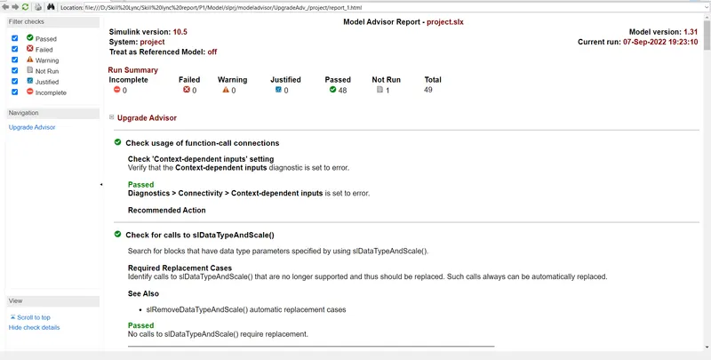
now after taking the model we need to check the model using Model Advisor Report and below is a screenshot of that shown below
Step 5
We need to do traceability and tangibility
we need to select the world Document which we need to take and to tag
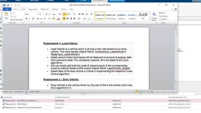
then need to open the model after right-clicking we need to select the word then we need to select from World then it will be done.
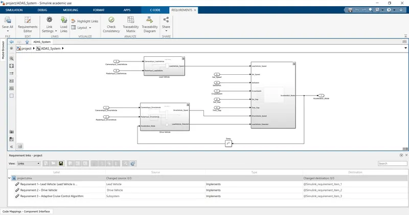
below is it is been staged to the model.
Result:
Here we had done the model using the requirement sheet which is given to us.
we had learnt how to create an SLLD
A model with help of a requirement sheet
How to create Codes from that model
how to tag different text with this.