Project 2 Adaptive Cruise Control
Adaptive Cruise Control
Aim: i)To develop the simulink model of Adaptive cruise control as per the requirements provided and to produce SLDD file.
ii) To do requirement tagging in the word file for given subsystem in the model.
iii) To perform MAP test on the model.
iv) To generate code with the help of embedded coder.
Answer:
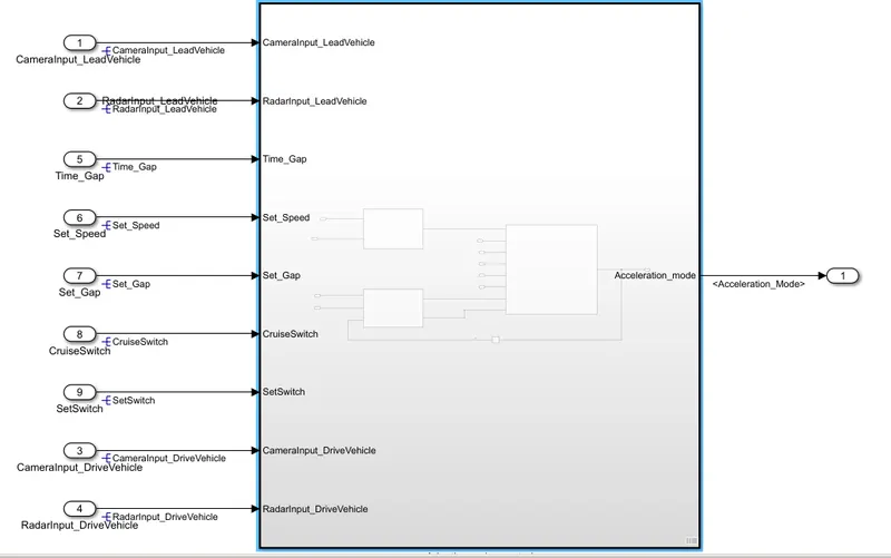
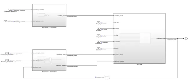
Fig_1:Simulink Model for Advance Cruise control
As seen in above image the Adaptive Cruise Control is implemented. All three requirements are fulfilled.
Requirement 1 and 2 are pretty much simple and easy to implement. The third requirement is also easy but time taking. It contains the chart and state machine logic as stated in the question requirements.
Requirement 1:
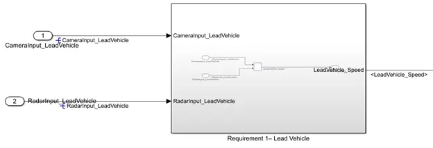
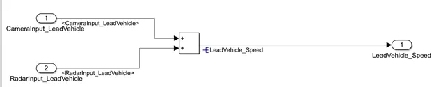
Fig_2:In and out view of Reuirement 1 Lead Vehicle
As per the requirement the two inputs are added CameraInput_LeadVehicle & LeadVehicle_Speed and new output is created which is LeadVehicle_Speed.
Requirement 2:
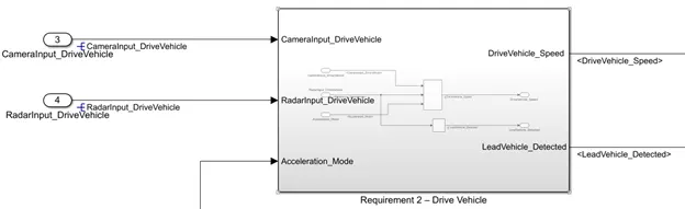
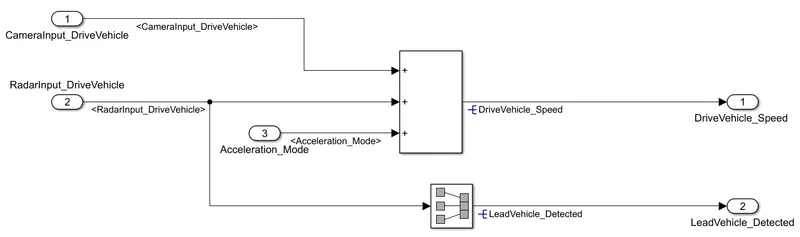
Fig_3: In and Out view of Requirement 2 – Drive_Vehicle
As per the requirement 2 , three inputs CameraInput_DriveVehicle, RadarInput_DriveVehicle and Acceleration_Mode are added togather and new output is created hich is DriveVehicle_Speed.
Also the second input RadarInput_DriveVehicle is renamed to LeadVehicle_Detected using signal conversion block.
Requirement 3:
As per the requirement 3 the input and output are made for the chart and state machine logic of adaptive cruise control.
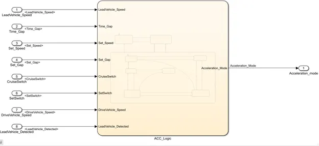
Requiremet 3a and 3b:
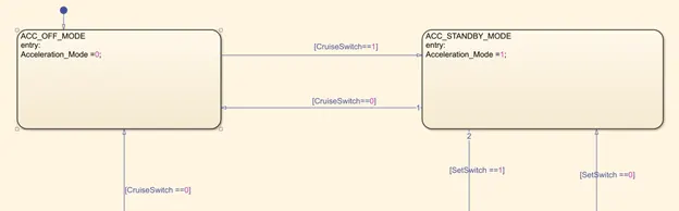
Below image depicts the requirements 3a and 3b, 3a is govern by Cruise_Switch and 3b is govern by Set_Switch and Cruise_Switch.
The transition condition are made as per the condition.
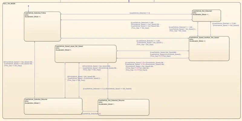
Requirement 3c:
It contains many part and many sub state machine logics.
Below screenshot represent the whole requirement 3c.
Requirement 3c (i),(ii),(iii),(iv),(v) and (vi):
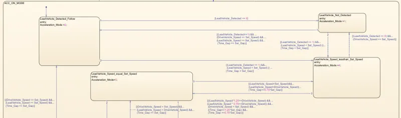
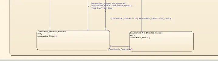
Requirent 3c is implemented with certain given conditions in the respective conditions:
Condition for Transition from
ACC_OFF_MODE to ACC_STANDBY_MODE is [CruiseSwitch==1]
and reverse true for [CruiseSwitch==0]
Condition for Transition from
LeadVehicle_Detected_Follow to LeadVehicle_Not_Detected is [LeadVehicle_Detected == 0]
and the reverse is true for
condition[(LeadVehicle_Detected==1) && ...
(DriveVehicle_Speed == Set_Speed) && ...
(LeadVehicle_Speed >= Set_Speed) &&...
(Time_Gap >= Set_Gap)]
and like wise all the conditions are implemented in the state machine logic chart.
Creation of Simulink Data directory:
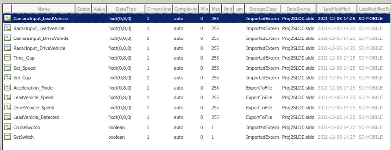
The simulik data directory is made as per the given question.
The sample time for each signal is taken as 0.01 sec. Here fixdt(0,8,0) represents the unsigned 8 bit datat type.
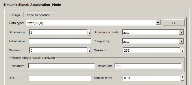
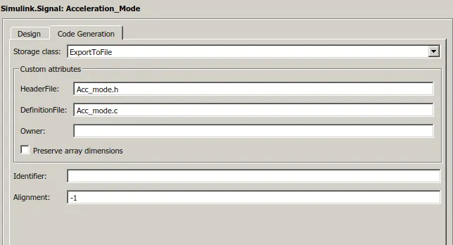
For the code generation part the header file and definition files are specified.
Requirement Tagging:
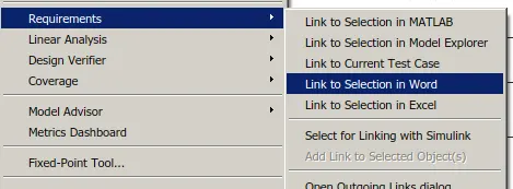
For requirement tagging first made a word file containing all the requirements and select the respective word for the respective subsytem.
Then right click on it and select requirement and select link to the word selection.
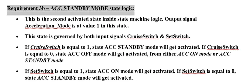
Also each state machine aslo tagged with the requirements.
MAB test For given Model:
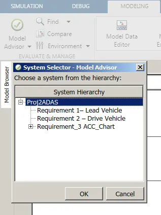
For doing the MAB test for the given model, click on the modeling tab and select model advisor.
Then after select the whole system for the model advisor test as per shown in the above image.
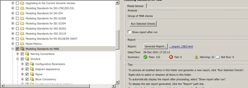
The MAB test should be perfect for code generation and there must be no failed status.
Creation of MIL and SIL tempelate :
MIL Tempelate:
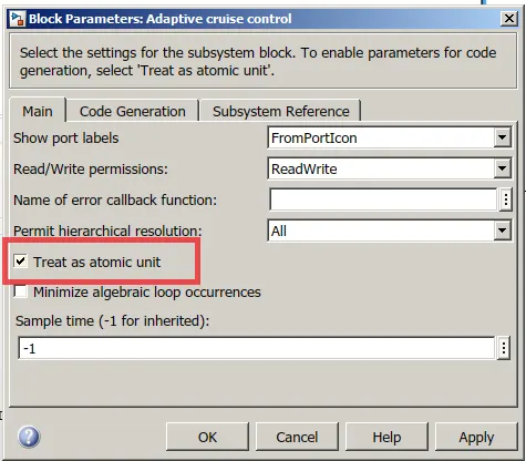
From the block parameters select the treat as atomic unit for MIL and SIL test.
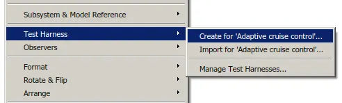
Now, right click on the subsystem and select Test Harness, then create for 'Name of sub system'
Then a dilog box will appear containing the sink and source option for the model test harness.
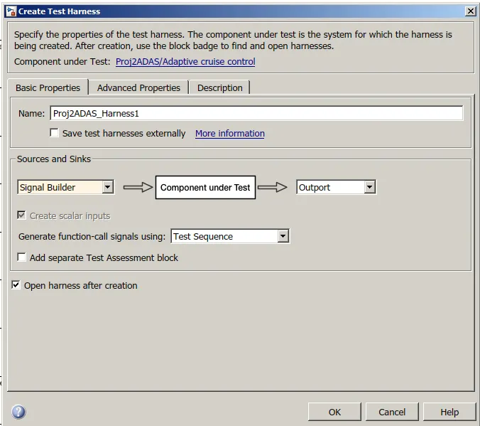
From that select signal builder as input and outport as sink. Then click OK.
Then new window will popup containing the testing arrangement as follows.
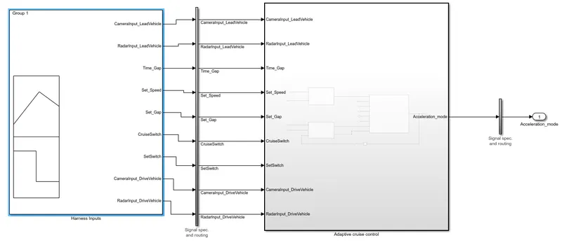
Here no test is performed , only the templete is generated.
It can be used to test that system, by importing signal into signal builder and checking the output.
SIL Tempelate:
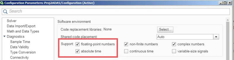
Support floating point number check is on according to the question.
- Use Embedded Coder to generate the code.
select Embeded coder from the app menu.
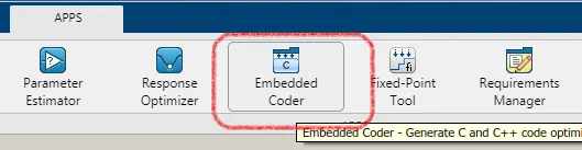
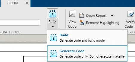
To generate code select "generate code" from the menu shown in above screenshot.
Then process of generating code will start.
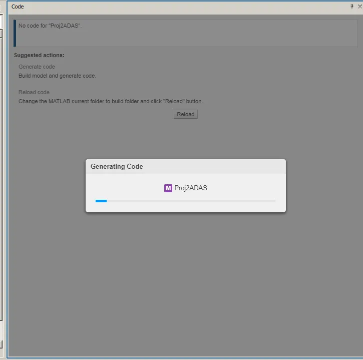
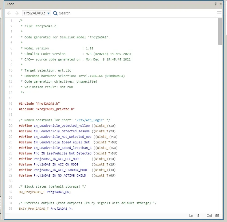
The generated code will lool like above image.
Now lets create SIL templete
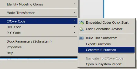
Click on Generate S function for the given subsystem.
The generated subsystem will look like as shown below for s-function.
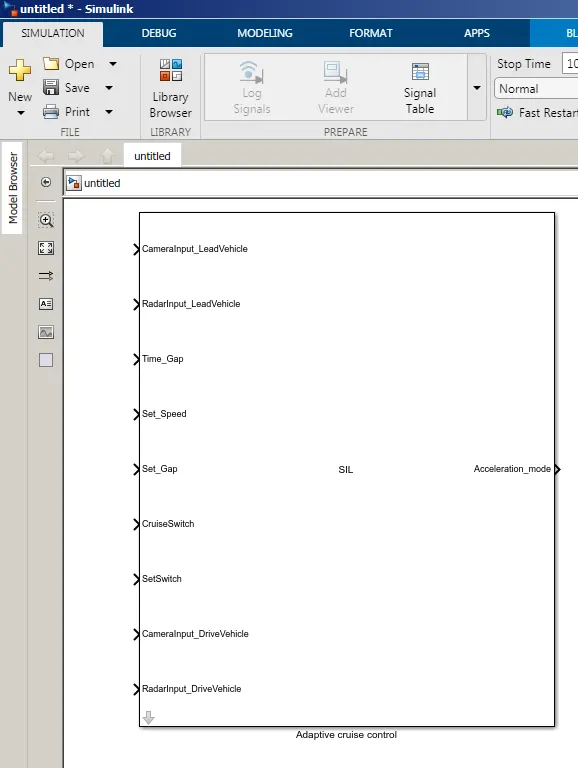
Here also no testing is performed only code is generated and S-function block is produced.
List Of files
| Proj2ADAS.docx -- Include Requirement tagging |
| Proj2ADAS.slx -- simulink Model |
| SILProj2ADAS.slx - SIL file |
| Proj2SLDD.sldd -- Simulink Data Directory File |