Project 2 Adaptive Cruise Control
Solution:
Creating a .sldd file of the data given:
Data given:
Signals & Calibration Data List:
|
Signal / Calibration Name |
Signal Type |
Data Type |
Dimension |
Min |
Max |
Initial Value |
Units |
|
CameraInput_LeadVehicle |
Input |
Uint8 |
1 |
0 |
255 |
- |
- |
|
RadarInput_LeadVehicle |
Input |
Uint8 |
1 |
0 |
255 |
- |
- |
|
CameraInput_DriveVehicle |
Input |
Uint8 |
1 |
0 |
255 |
- |
- |
|
RadarInput_DriveVehicle |
Input |
Uint8 |
1 |
0 |
255 |
- |
- |
|
Time_Gap |
Input |
Uint8 |
1 |
0 |
255 |
- |
- |
|
Set_Speed |
Input |
Uint8 |
1 |
0 |
255 |
- |
- |
|
Set_Gap |
Input |
Uint8 |
1 |
0 |
255 |
- |
- |
|
CruiseSwitch |
Input |
Boolean |
1 |
0 |
1 |
- |
- |
|
SetSwitch |
Input |
Boolean |
1 |
0 |
1 |
- |
- |
|
Acceleration_Mode |
Output |
Uint8 |
1 |
0 |
255 |
- |
- |
|
LeadVehicle_Speed |
Output |
Uint8 |
1 |
0 |
255 |
- |
- |
|
DriveVehicle_Speed |
Output |
Uint8 |
1 |
0 |
255 |
- |
- |
|
LeadVehicle_Detected |
Output |
Uint8 |
1 |
0 |
255 |
- |
- |
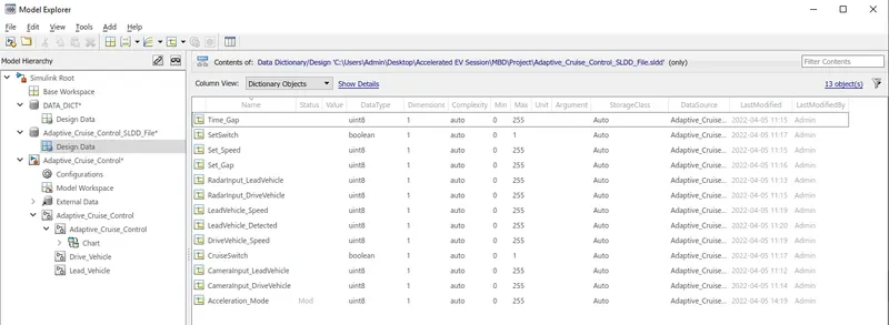
Therefore as shown in the above figure, the .sldd file of the given data has been created. i.e. Adaptive_Cruise_Control_SLDD.
Requirement 1– Lead Vehicle:
- Lead Vehicle is a vehicle which is driving in the road ahead of our drive vehicle. Two input signals (Signal Name: CameraInput_LeadVehicle & RadarInput_LeadVehicle).
- Ideally sensor fusion techniques will be deployed to process & analyze data from camera & radar. For complexity reasons, let’s not adapt to any such algorithms.
- We can simply add both the radar & camera inputs & the corresponding output is read as Speed profile output (Signal Name: LeadVehicle_Speed).
- Speed data of the lead vehicle is critical in implementing the Adaptive Cruise Control algorithm.
Asper the given Requirement1, the Subsystem has been ceated and the simulink model has been implemented.
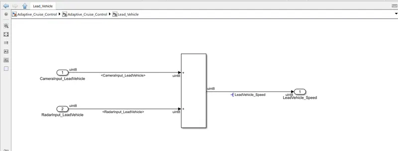
The above fig. shows us the implementation of the Requirement1
- ADD block has been used for adding simply two signals and giving an output to the outport block
- two inport block has been used for giving input of two signals.
Requirement 2 – Drive Vehicle:
- Drive Vehicle is the vehicle driven by the user & this is the vehicle which has ACC algorithm in it.
- Like the Lead Vehicle, Drive Vehicle algorithm also has 2 input signals (Signal Name: CameraInput_DriveVehicle, RadarInput_DriveVehicle) & one signal coming as an Input to this subsystem (Signal Name: Acceleration_Mode) – three inputs into this requirement in total.
- Like the above requirement, sensor fusion techniques will also be deployed here, for complexity reasons we are ignoring them.
- Two output signals come from this subsystem (Signal Name: DriveVehicle_Speed & LeadVehicle_Detected).
- Signal DriveVehicle_Speed is summation of three input signals mentioned above & LeadVehicle_Detected is renamed from Input Signal RadarInput_DriveVehicle by mere use of Signal Conversion block.
Asper the given Requirement2, the Subsystem has been ceated and the simulink model has been implemented.
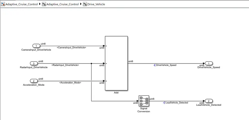
The above fig. shows us the implementation of the Requirement2
- ADD block has been used for adding three signals and giving an output to the outport block
- Three inport block has been used for giving input of three signals.
- A signal conversion block has been used for giving the output through outport2
Requirement 3 – Adaptive Cruise Control Algorithm:
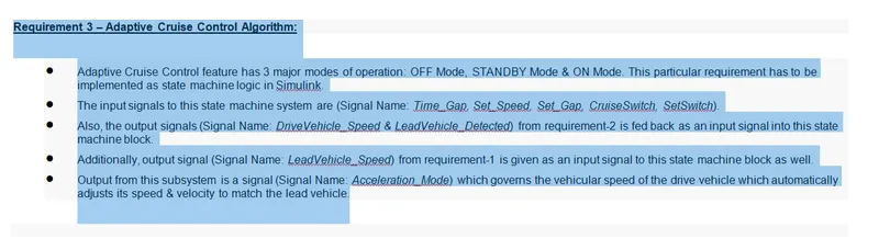
- Adaptive Cruise Control feature has 3 major modes of operation: OFF Mode, STANDBY Mode & ON Mode. This particular requirement has to be implemented as state machine logic in Simulink.
- The input signals to this state machine system are (Signal Name: Time_Gap, Set_Speed, Set_Gap, CruiseSwitch, SetSwitch).
- Also, the output signals (Signal Name: DriveVehicle_Speed & LeadVehicle_Detected) from requirement-2 is fed back as an input signal into this state machine block.
- Additionally, output signal (Signal Name: LeadVehicle_Speed) from requirement-1 is given as an input signal to this state machine block as well.
- Output from this subsystem is a signal (Signal Name: Acceleration_Mode) which governs the vehicular speed of the drive vehicle which automatically adjusts its speed & velocity to match the lead vehicle.
Asper the given Requirement3, the Subsystem has been ceated and the simulink model has been implemented.
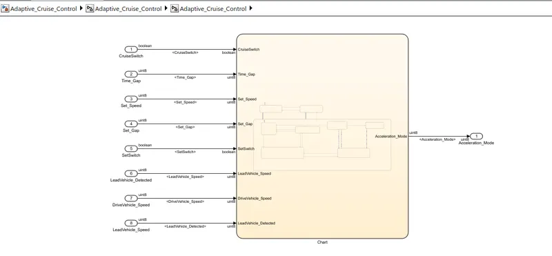
The above fig. shows us the implementation of the Requirement3
Chart Implementation:
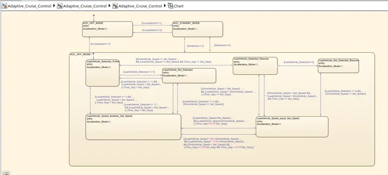
- All the requirements has been implemented in the above chart as per shown in the above figure.
- "ACC_OFF_MODE" is the default entry point of the chart
- Adaptive cruise control is having total two mode. "ACC_OFF_MODE" & "ACC_STANDBY_MODE".
- We have two main conditions of CruiseSwitch and SetSwitch.
Defining the input and output signals of the Chart:
- Nodelling -> Symbols pane
Therefore, a signal dashboard will be appeared.
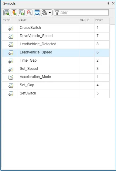
Therefore the input and output signals has been defined in the symbols pane, as shown in the above figure.
- CruiseSwitch -> Input Signal; port1
- Acceleration_Mode-> output Signal; port1
- Time_Gap-> Input Signal; port2
- Set_Speed-> Input Signal; port3
- Set_Gap-> Input Signal; port4
- SetSwitch-> Input Signal; port5
- LeadVehicle_Speed-> Input Signal; port6
- DriveVehicle_Speed-> Input Signal; port7
- LeadVehicle_Detected-> Input Signal; port8
Finally a chart can be seen with its input and output signals.
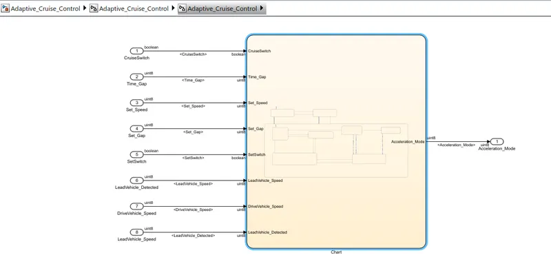
Once the chart is Implemented,
Requirement 1,2, & 3 are merged all together asper the given condition.
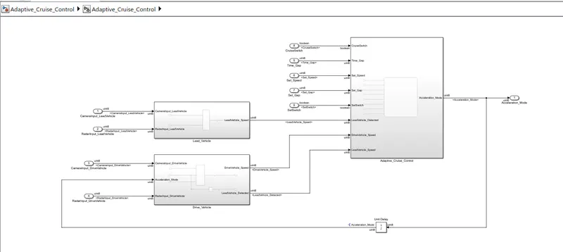
The above figure shows us the merged Simulink model of the "Adaptive Cruise Control"
- A UNIT Delay block has been used for giving the feedback of Acceleration_Mode.
Adaptive Cruise Control Simulink Model:
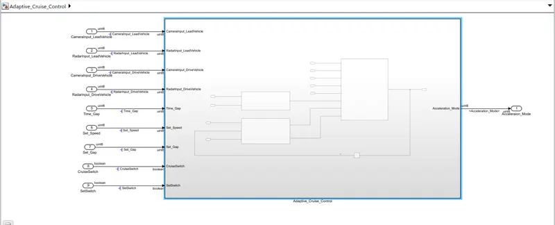
- The above figure shows us the simulink model of Adaptive_Cruise_control.
- All the Three requirements are implemented in the separate subsystem, and all are merged in a single Adaptiv_Cruise_Control subsystem.
- It consist of total 10 ports; where 9 are inports and 1 is the outport.
Requirement Tagging:
- Make a Word document of the question
- save that word document in a same folder.
- highlight the Requirement that has to be tagged.
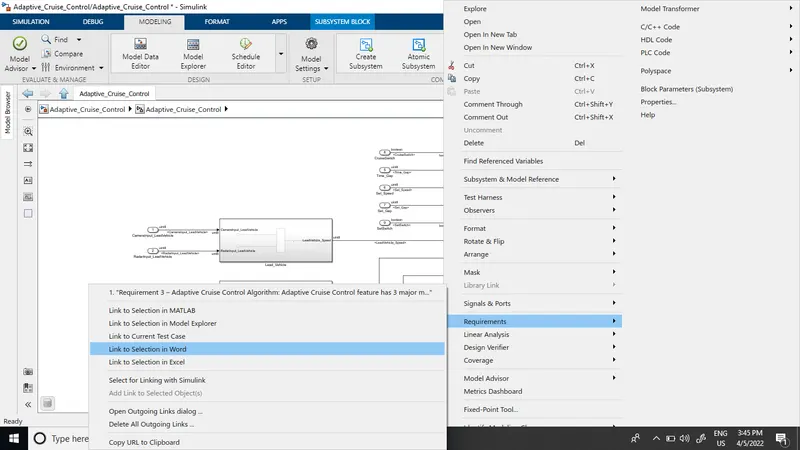
- Open simulink subsystem of Requirement1
- Right click that subsystem-> Requirements-> Link to Word
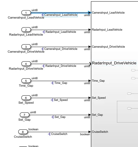
Signal Resolving:
- Click the signal that has to be resolved
- Go to properties-> Enter signal name
- Tick signal Resolve option
- Apply & OK
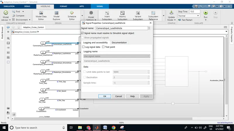
- Once the signal is resolved, Signal can be seen as shown in the below figure.
Signal Propogation:
- Once the signal Resolving is done,
- Signal has to be propogated further.
- Click on signal that has to be propogated
- go to properties
- Tick, signal propogation
- Apply & OK
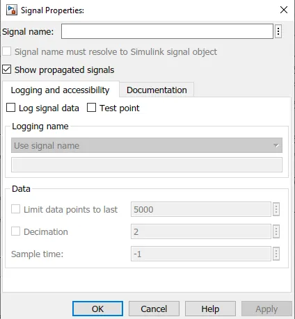
Therefore, signal will be propogated.
Similarly propogate all the signals of the model, as shown in the fig.
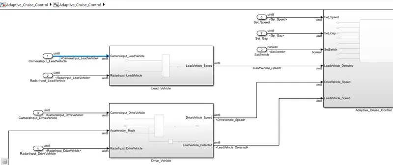
Once the model is ready
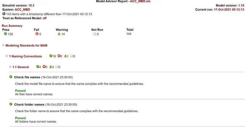
MAB guidelines test:
- Select the model
- Go to model Advisor
- Under "TASK" Only select "Modelling standards of MAB"
- Select "Generate report after Check"
- Ok
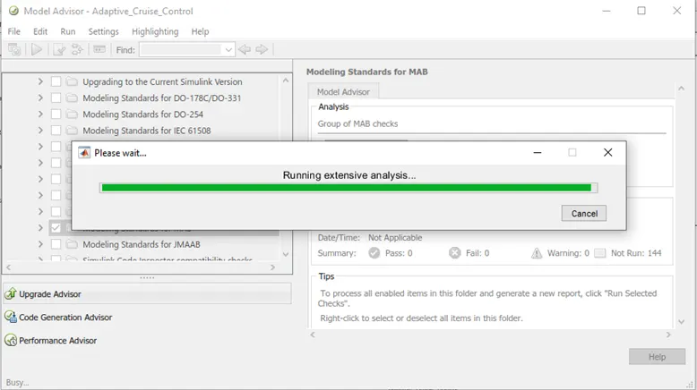
Therefore model advisor will take some time to compile and get the results.
After all checks, a A pass report of model advisor can be seen.
Code Generation:
- Right click the model whose code has te be generated
- c/c++ code
- Select S-Function option
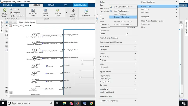
- Click on generate code option.
- Therfore the Code will be generated of the given model.
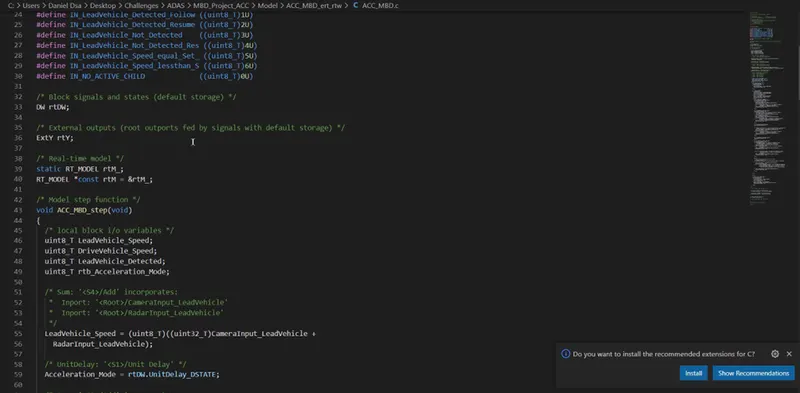
The above figure shows the Generated code Snap.