Project 2
MOLD DESIGN FOR CPU FAN BEZEL
Introduction
A conventional mold consists of core & cavity blocks, sliders, inserts, air vents, cooling system etc. for the given part design. The mold design for the given part, cpu fan bezel is very challenging and it requires many aspects for its design. The best mold for the given cpu fan bezel and the process is explained in detail in the following report.
This mold contains many systems and sub-systems in it, every system and sub-system has their particular tasks and they are explained in detail.
Design of Core & Cavity surfaces
- Firstly the part need to be scaled as per the shrinkage percentage. As the required material is ABS it need to be scaled 1.006 times the original size.
- Then check the Drafts given in the part for safe ejection of the part from the mold.
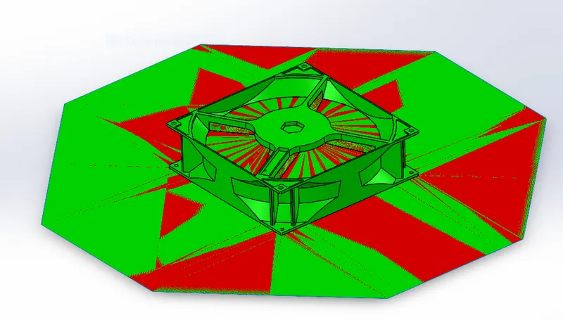
- Now the parting line needs to be given and the shutoff surfaces need to be closed to separate the core and cavity surfaces over the given part.
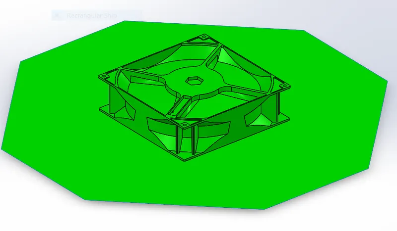
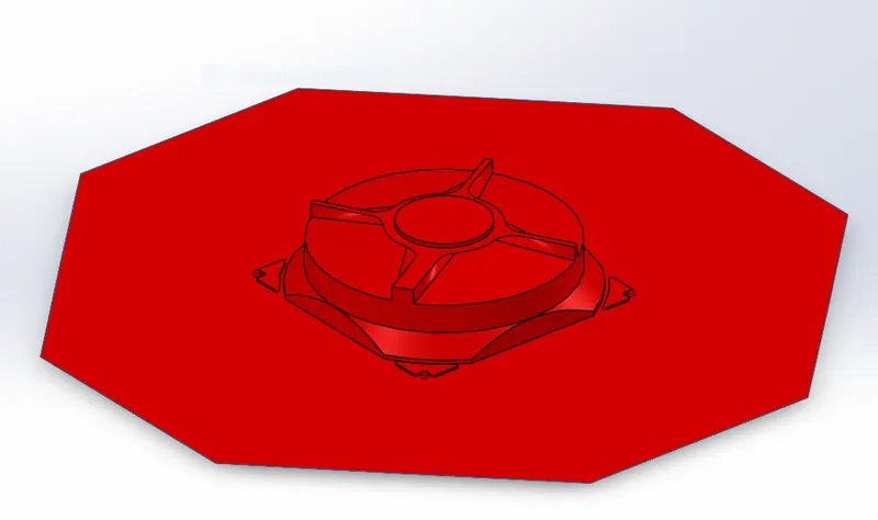
- Then use the ruled surface command and sweep the surface over the parting and create the copies of the surface for both core and cavity and then knit with the respective surfaces.
- There are 4 hollow regions in the given fan bezel model, they need to be filled with the lofted surfaces and then knit with the respective surfaces.
The parting surfaces for the cpu fan bezel model looks like
Design of Core and Cavity Blocks
- After Creating the surfaces, a new assembly need to be created for Mold alignment of cpu fan bezel. New parts need to be added as core and cavity parts.
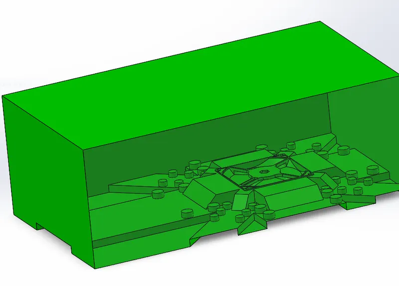
- Edit the core part to make a core block, sketch a rectangle on the top plane and then Extrude on both sides and then cut with the offset surface made from the Core surface of the fan bezel model, hence the Core block is created.
- The same process goes with the cavity block as well
both core and cavity blocks looks as follows
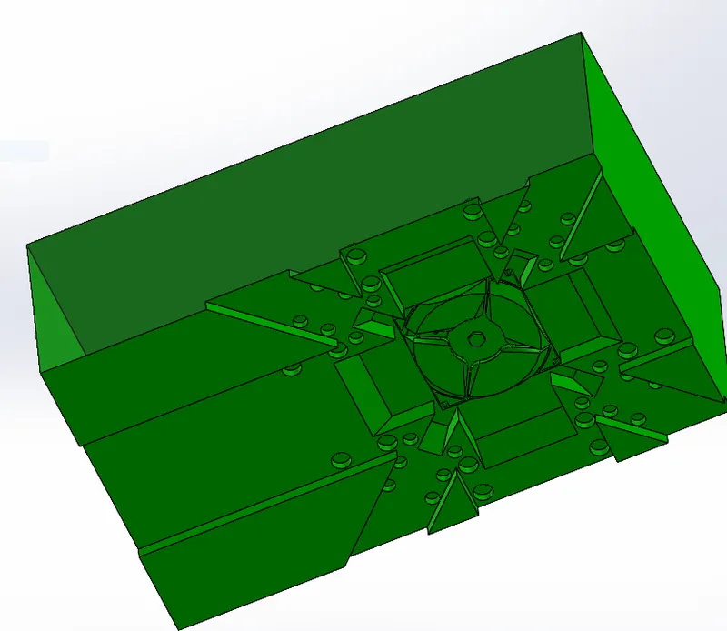
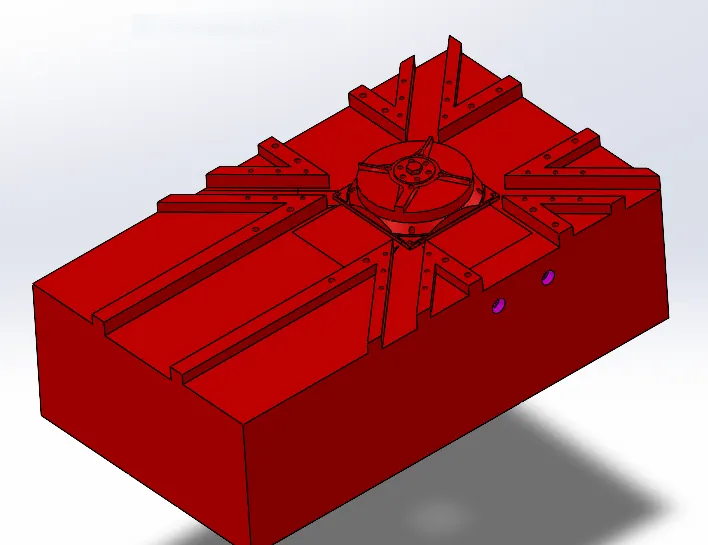
Design of Sliders for CPU fan Bezel
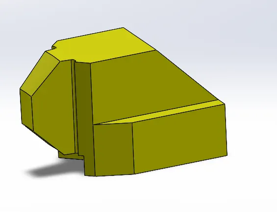
- The sliders are the most complicated and Challenging Parts to design in the fan bezel component, there are many undercuts that needs to be filled by the sliders.
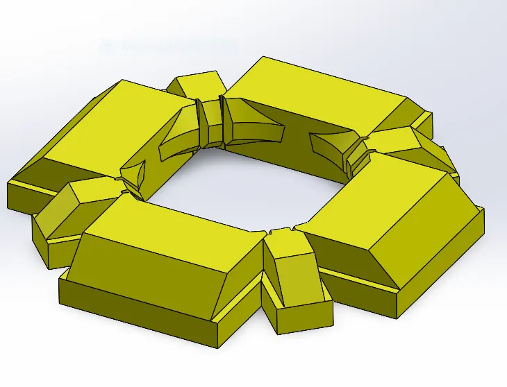
- There are totally 8 undercuts all around the model where the sliders are need to be added
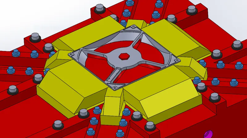
The position of the slider is
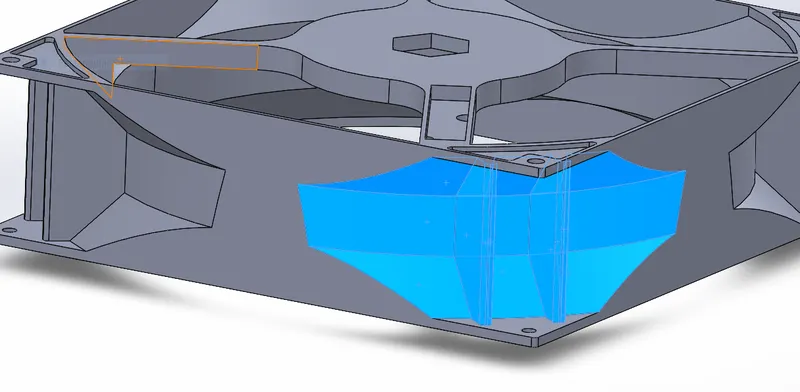
- All the side faces are the undercuts, the sliders are designed by the split and cut with surface command of the cavity surface.
- Each 4 sliders are identical Because of the isometry of the faces.
The sliders for this Fan bezel looks like
- For 4 faces
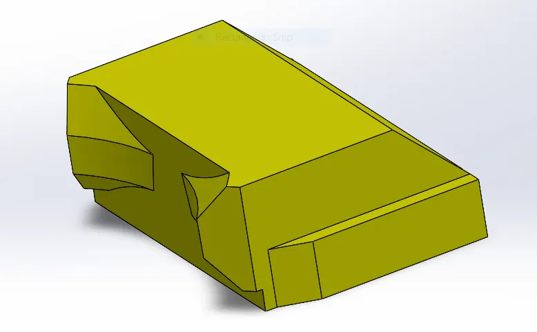
- For 4 corners
sliders alignment
Inserts Blocks
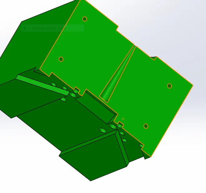
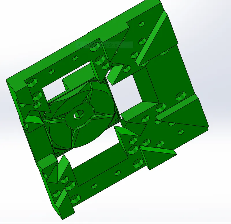
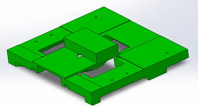
- There is only 2 insert to be placed, which are seperated only for the purpose of sprue and Air vents.
- There are no deep cuts in the model to creat inserts.
- The holes area made for the screws to hold the inserts, using Hole wizard command.
The inserts are as follows

Air vents
- The Air vents have been given on the 3 sides of the fan bezel with initial relief of 0.25mm for 2mm long and relief of 1mm till outside the block.
- Due to thin width and deep cut these airvents push the requirement to form a insert block separately.
The air vents in the mold looks like


sectional view

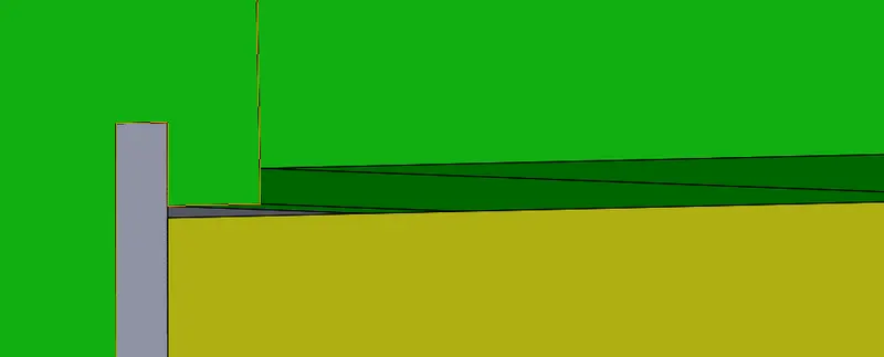
The air vent can be seen clearly in the sectional view that releases the air pressure during the injection molding and avoids many defects in the parts.
Sprue and Runner Design
- The purpose of sprue is to carry the molten material through the mold to convert into the part, the sprue has a conical draft of 3.5 degree outwards to ensure easy removal of the part
The sprue looks like
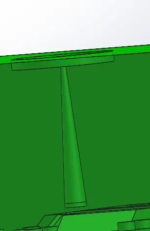

- In the 2nd picture above we can see the path way to the runner from the sprue.
- The runner is design as per the known formula for radius, the runner is upto the central hexagonal region of the fan bezel part
- There exists the gate to enter the hollow region to get converted into the part.
The runner and the gate system looks like
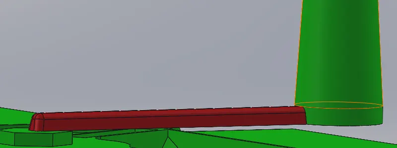
in the above picture the red highlighted region is the runner that caries the molten material to the gate
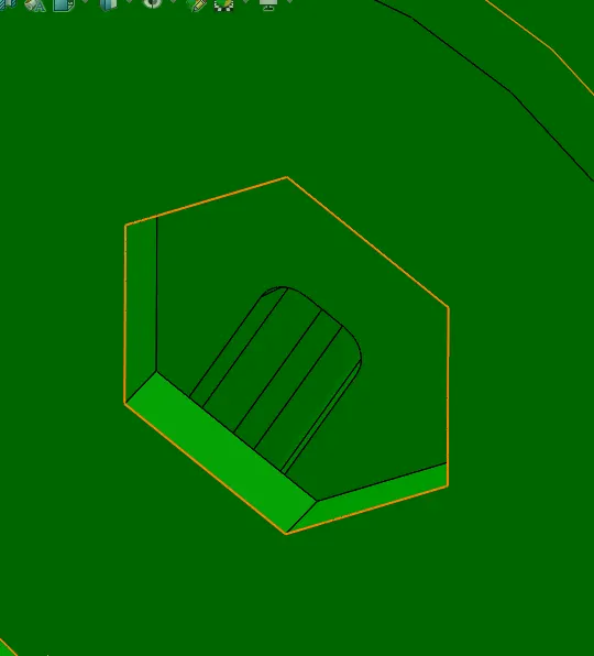
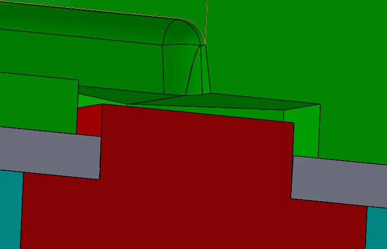
- In the above pictures we can see the hexagonal gate given to the mold.
- In the 2nd picture we can see the sectional view of all the core, cavity blocks with the part as well.
- Hence we understand how the molten material enters the part region.
- In the 2nd picture the gap between the red core block and the hexagonal gate is 2mm through which the molten material enters.
Design of Ejection system
- The ejection system for this model has 2 kinds of ejector pins, they are D shaped and circular pins.
- There are 4 D shaped pins and 10 circular ejector pins in the model
- The 4 pins are ejecting the curved surface so they are D shaped
- The remaining pins are circular as they push the3 flat surface.
- the relief is also provided to the pins at the height of 12mm from the model.
the pin system look like
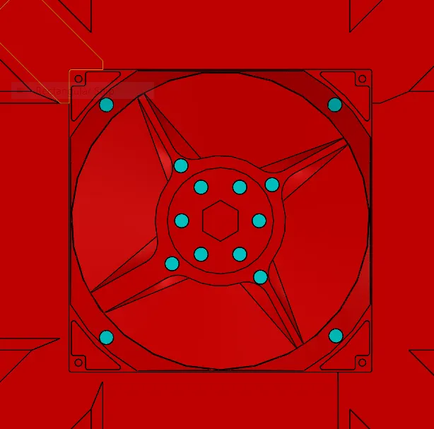

In the above pictures the four corner pins are D shaped pins and the centre ones are circular.
The Yellow surface is the surface of the ejector plate that pushes the ejector pins.
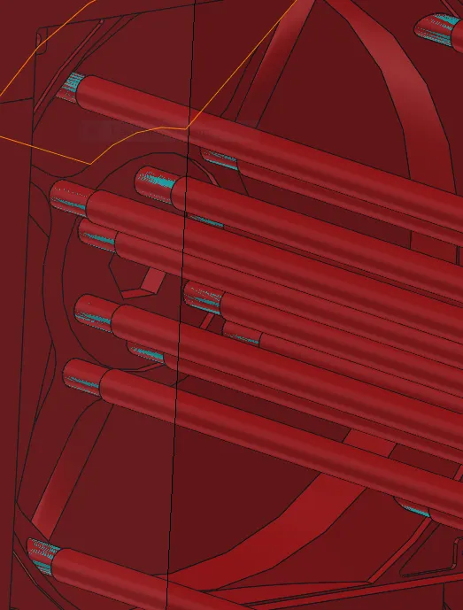
The relief system is designed as shown in the above figure
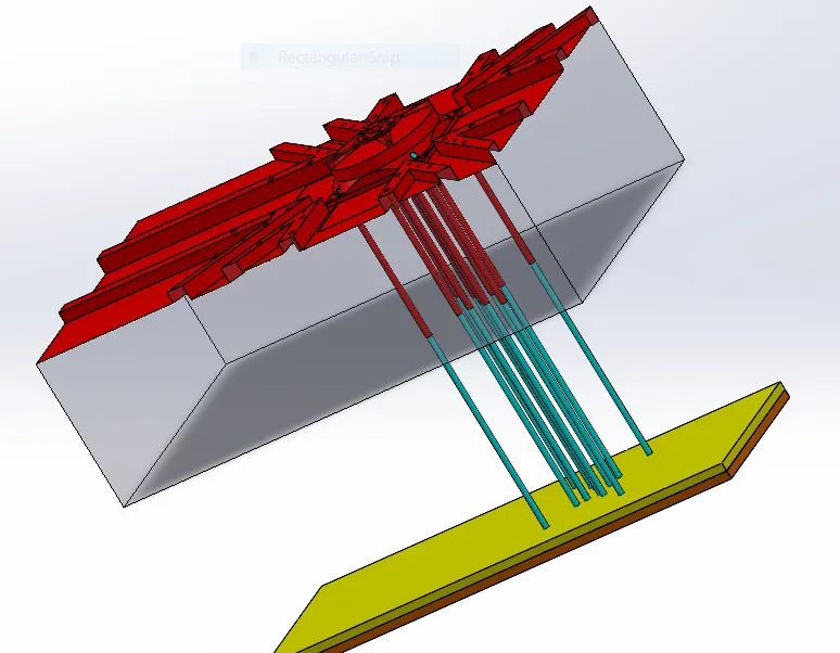
- The Orange coloured body in the bottom is the ejector back plate which supports the ejector plate and the ejector pins.
Cooling System Design
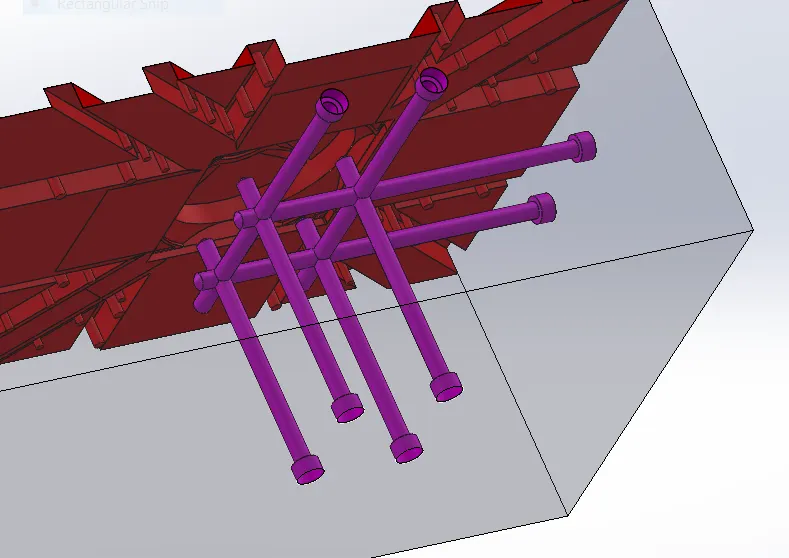
- The Serial cooling system is to be designed for this model, through the coolant flows in and out.
- The Hole wizard command is used to design the cooling system, by making various pores in the core block as the part is mostly molded in the core block.
The cooling system for this mold looks like
Design of Washers
- Two types of washers are designed for the model as there are 2 different type of sliders, based upon their sizes.
- The side face sliders have one size washers, where the corner sliders have a different size sliders.
- They are created by inserting a new part into the assembly and then by extruding and the sketch pattern command.
- Then they are aligned to the slider path.
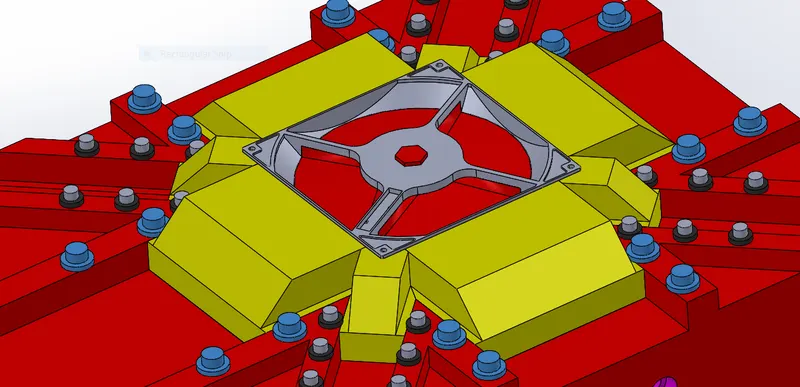
In the above picture the Blue colour highlighted Parts are the face slider washers
In the above picture the Blue colour highlighted Parts are the corner slider washers.
Assembly
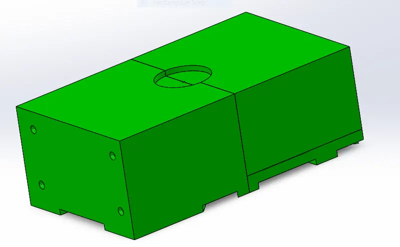
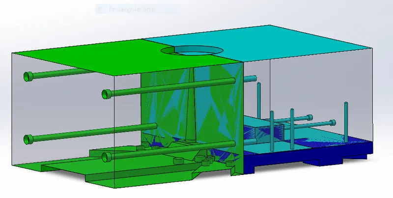
Some Views of the molf of CPU fan bezel are as follows
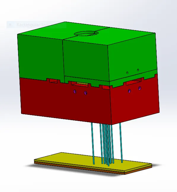
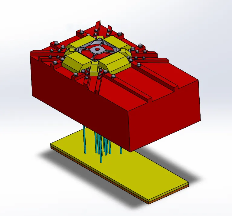
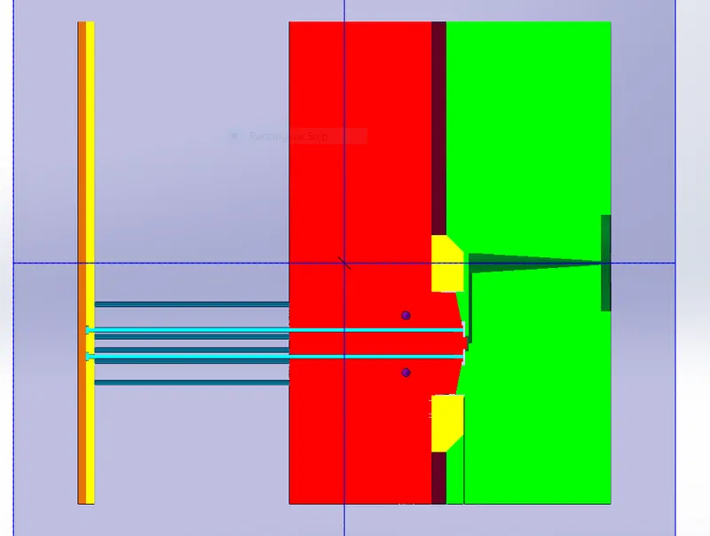
The above Sectional view shows us how the molding process of the fan bezel works,
The molten material enters the cavity form the left through he sprue to the runner and enter the molding region through the hexagonal gate.