Project 2
AIM & PROCEDURE
To design a Pre Engineered building (Rigid frame structure) as per architectural drawings.
PROCEDURE
The loads considered for the design of the PEB is given below.
Loadings
1. DEAD LOAD
Rafters
Self-weight of the structure = 1.05 (5% for connections)
Weight of Purlin = 10 `kg//m^2`
Weight of Portal = 15 `kg//m^2` (Purlin weight inclusive)
Total load on intermediate Rafters = 15 `kg//m^2` x 8.045 m x 10 x `10^-3` = 1.21 `kN//m` (Conservatively taken as 8.405 m)
Total load on intermediate Rafters = 15 `kg//m^2` x 4.0225 m x 10 x `10^-3` = 0.605 `kN//m` (Conservatively taken as 1.21/2)
Mezzanine
Self-weight of 150 mm slab = 0.15 m x 25 `kN//m^3` = 3.75 `kN//m^2`
Floor Finish = 1.5 `kN//m^2`
Additional = 0.625 `kN//m^2` (Decking sheet weight inclusive)
Total = 5.875 `kN//m^2`
230 mm Brick wall on Mezzanine for 4 m height = 20 `kN//m^3` x 0.23 m x 4 m = 18.4 `kN//m`
2. LIVE LOAD
Roof & Canopy
Total load on intermediate Rafters & Canopy = 57 `kg//m^2` x 8.045 x 10 x `10^-3` = 4.6 `kN//m` (Conservatively taken as 8.405 m)
Total load on intermediate Rafters & Canopy = 57 `kg//m^2` x 4.0225 x 10 x `10^-3` = 2.3 `kN//m` (Conservatively taken as 4.6/2)
Mezzanine
Total load on mezzanine = 400 `kg//m^2` x 10 x `10^-3` = 4.0 `kN//m^2`
3. COLLATERAL LOAD
Roof
Electrical Fittings = 10 `kg//m^2` x 10 x `10^-3` = 0.1 `kN//m^2`
Sprinklers = 3 `kg//m^2` x 10 x `10^-3` = 0.03 `kN//m^2`
Rockwell insulation = 10 `kg//m^2` x 10 x `10^-3` = 0.1 `kN//m^2`
Bubble wrap insulation = 5 `kg//m^2` x 10 x `10^-3` = 0.05 `kN//m^2`
Solar panel = 15 `kg//m^2` x 10 x `10^-3` = 0.15 `kN//m^2`
False ceiling = 10 `kg//m^2` x 10 x `10^-3` = 0.1 `kN//m^2`
Total Load = 0.53 `kN//m^2`
Total load on intermediate Rafters = 0.53 `kN//m^2` x 8.045 m = 4.26 `kN//m` (Conservatively taken as 8.405 m)
Total load on intermediate Rafters = 57 `kg//m^2` x 4.0225 m = 2.13 `kN//m` (Conservatively taken as 4.26/2)
Mezzanine
Electrical Fittings = 10 `kg//m^2` x 10 x `10^-3` = 0.1 `kN//m^2`
False ceiling = 10 `kg//m^2` x 10 x `10^-3` = 0.1 `kN//m^2`
Total Load = 0.2 `kN//m^2`
Service line weight = 150 `kg//m`
8m span and 1m width = 150 `kg//m` x 8 `m` = 12 `kN` at 1m (Point Load)
8m span and 1m width = 12 `kN//m` x 1 `m` = 12 `kN//m` (Moment)
4. WIND LOAD
Wind speed= 39 m/s (Coimbatore)
K1=1; K2= 1.05(terrain category 1); K3=1: K4=1(cyclone zone)
Design Wind speed
`V_z` = `V_b` `k_1` `k_2` `k_3` `k_4`
`V_z` = 39 x 1.0 x 1.05 x 1.0 x 1.0
`V_z` = 40.95 `m//sec`
Design Wind Pressure
`P_z` = 0.6 `V_z^2`
`P_z` = 0.6 x `40.95^2`
`P_z` = 1006.14 `N//m^2`
ka=0.8; kd=0.9; kc=0.9
since Kd x ka x kc = 0.65 < 0.7 = 0.7 is taken
`P_d` = 0.7 `P_z`
`P_d` = 0.7 x 1006.14 `N//m^2`
`P_d` = 0.704 `kN//m^2`
Cpi= +/- 0.2
`h/w` = `10.05/60` = 0.1675
`l/w` = `170/60` = 2.833
WALL
A B C D
0 0.7 -0.25 -0.6 -0.6
90 -0.5 -0.5 0.7 -0.1
ROOF
0 90
EF GH EG FH
-0.86 -0.4 -0.8 -0.4
CANOPY
Roof Angle
`tan theta` = `1/20`
`theta` = `tan^-1 (1/20)`
`theta` = 2.86 degree
Cp (negative - uplift)=-1.08
Cp (positive)=0.35
`F = (C_(pn) - C_(px)) A_e P_d`
Expansion joint is modelled with connecting members which should be specified as INACTIVE in specifications.
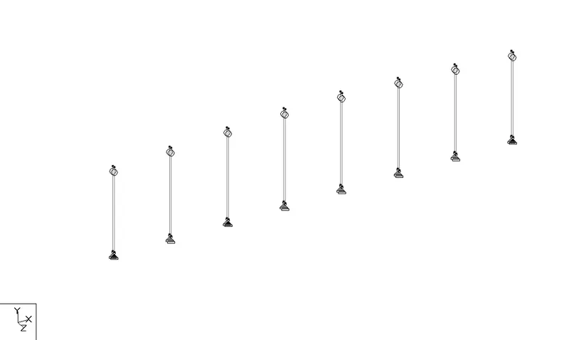
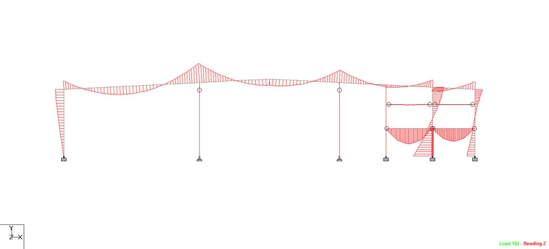
Bending Moment of a Frame
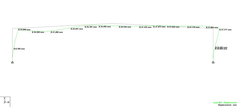
Lateral Deflection Limit = L / 150
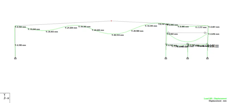
Vertical Deflection Limit = L / 240
Maximum Utilization Ratio is 0.965