Project 2
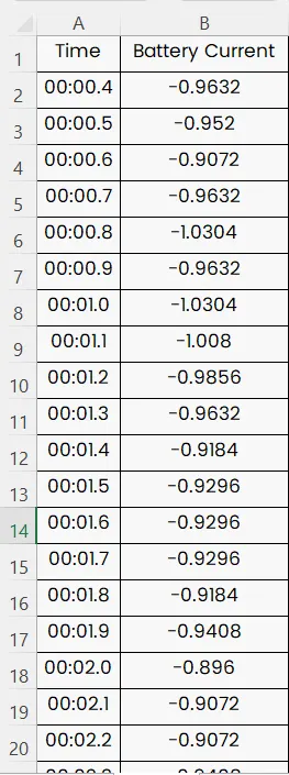
Using MATLAB/simulink and the drive cycle from the attached excel sheet, find-
- The max heat generation of the battery
- The SOC of the battery at 2 *104second of the battery operation
|
Time |
Time Step |
Battery Current |
|
00:00.4 |
0.1 |
-0.9632 |
|
00:00.5 |
0.2 |
-0.952 |
|
00:00.6 |
0.3 |
-0.9072 |
|
00:00.7 |
0.4 |
-0.9632 |
|
00:00.8 |
0.5 |
-1.0304 |
|
00:00.9 |
0.6 |
-0.9632 |
|
00:01.0 |
0.7 |
-1.0304 |
|
00:01.1 |
0.8 |
-1.008 |
|
00:01.2 |
0.9 |
-0.9856 |
|
00:01.3 |
1 |
-0.9632 |
|
00:01.4 |
1.1 |
-0.9184 |
|
00:01.5 |
1.2 |
-0.9296 |
|
00:01.6 |
1.3 |
-0.9296 |
|
00:01.7 |
1.4 |
-0.9296 |
|
00:01.8 |
1.5 |
-0.9184 |
|
00:01.9 |
1.6 |
-0.9408 |
|
00:02.0 |
1.7 |
-0.896 |
|
00:02.1 |
1.8 |
-0.9072 |
|
00:02.2 |
1.9 |
-0.9072 |
|
00:02.3 |
2 |
-0.9408 |
|
00:02.4 |
2.1 |
-0.9296 |
|
00:02.5 |
2.2 |
-0.9296 |
|
00:02.6 |
2.3 |
-0.9968 |
|
00:02.7 |
2.4 |
-0.9968 |
|
00:02.8 |
2.5 |
-0.9408 |
|
00:02.9 |
2.6 |
-0.9408 |
|
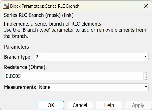
Battery resistance |
2 milli ohm |
Consider the battery resistance is 0.5m Ohm, delta time is 0.1 and entropic factor is 2
AIM:
Calculating the maximum heat generated by the battery from a given drive cycle. And SOC calculation using MATLAB/Simulink for 208 seconds of the battery operation.
Theory:
Heat Generation:
Batteries generate heat during charge and discharge due to enthalpy changes, electrochemical polarization, and resistive heating inside the cell. Temperature variation inside the batteries can lead to the uneven temperature distribution which creates uneven charge/discharge behavior within the battery pack. So, thermal runaway may occur in a cell when heat is not properly controlled and possibly cause fire and explosion.
a. The max heat generation of the battery
Maximum joule heat = I^2 * R * t
The maximum current in the drive cycle (I) = -0.896
Battery Resistance (R) = 0.5 m ohm
Time = 2 minutes = 120 seconds
Maximum joule heat = (-0.896) ^2 * 0.5milli * 120
= 48.16 mill joule
The maximum joule heat is 48.16milli joule
This is the joule heat it is given that the entropic heat is twice that of joule heat
Maximum heat generated = maximum joule heat + entropy heat
= 48.16 milli + 2
= 50.16 m joules.
Maximum heat generated 50.16 milli joules
b. The SOC of the battery at 2 *104second of the battery operation
In MATLAB/Simulink, I am building a model to find the SOC of the battery at 208 seconds of battery operation.
Theory:
SOC:
The SOC is the level of charge of an electric battery related to its capacity. The units of SOC are percentage points (0% = empty; 100% = full). It is also defined as the ratio of the remaining capacity to the fully charged capacity.
Techniques for SOC estimating
- The battery voltage translation
- The battery current integration ("Coulomb Counting")
Voltage Translation
In many systems, a simple voltmeter is used as a SOC indicator: the battery voltage decreases more or less linearly as the battery is discharged. This effect is more or less pronounced depending on the battery chemistry. In particular, the voltage in a Lead Acid battery decreases significantly as it is discharged. Knowing the relationship of battery voltage and SOC allows the voltmeter to be calibrated to report SOC: that is, the voltage is translated to an estimated SOC.
A major limitation with this technique is that the battery voltage is also affected by temperature and battery current. Knowing the way temperature and current affect the voltage allows one to compensate for those effects to a great extent, allowing Voltage Translation to be a used with many battery chemistries.

Using Voltage Translation to estimate SOC in a lead acid battery.
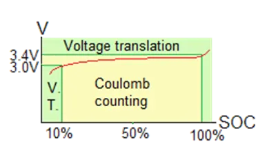
Unfortunately, for most of its SOC range, the voltage of a Li-Ion battery remains very constant, making Voltage Translation impractical. Yet, the voltage of a Li-Ion battery does change significantly at both ends of its SOC range: the voltage increases rapidly when full, and drops significantly when it starts getting empty. Therefore, Voltage Translation can be use to estimate SOC of a very full or very empty Li-Ion battery.

Using Voltage Translation to estimate SOC with Li-Ion cells.
Coulomb Counting
Integrating the current into or out of a battery gives the relative value of its charge, just as counting currency in and out of a bank account gives the relative amount in the account. The operative word here is "relative": like all definite integrals, "Coulomb Counting" needs a starting point. If the initial charge in the battery is known, from then on "Coulomb Counting" can be used to calculate its SOC.
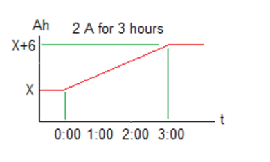
For example, a 2 A current into a battery, for 3 hours, will add 2 * 3 = 6 Ah to the battery charge. If the battery capacity is 24 Ah, that will increase its SOC by 6 / 24 = 25 %. That's 25 % more than it had been at the beginning; but, without knowing what the beginning SOC was, we do not know the final SOC.
Using Coulomb Counting to estimate relative SOC changes.
Depending on the battery chemistry, Coulomb Counting can be a very accurate technique.
Coulomb Counting doesn't work as well with Lead Acid batteries, because:
- The significant leakage current within Lead Acid batteries does not go through the battery current sensor and is therefore not taken into account
- Not all the charge in a Lead Acid battery is converted into useful work: some of it is converted in waste heat, an effect that is characterized by the Peukert exponent
On the other side, Coulomb Counting does work as well with Li-Ion batteries, because of their low leakage and good Peukert exponent.
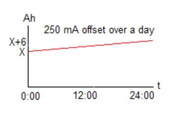
Another limitation of Coulomb Counting is drift. In any integration, any small, constant error in the variable being integrated results in a drift in the result. In the case of Coulomb Counting, any small offset in the measurement of battery current, will result in the SOC drifting up (or down) over time.
Drift in Coulomb Counting due to small offset in the measured current.
Drift can become significant in applications that, for long periods, use very little battery current or shuttle current back and forth:
- Stand-by batteries:
- Even if the battery is full, a small offset in the current sensor will result in the reported SOC drifting all the way to 0% over time
- Hybrid car (HEV) batteries:
- Stand-by batteries:
- The car uses energy from the battery when it needs it, and replenishes it when it can, trying to keep the SOC at about 50%;
- Well, the reported SOC may very well stay around 50%; but, over time, because of some small offset in the current sensor's output, the actual SOC will drift up or down, and eventually the actual battery charge approaches either the full or empty state
Therefore, Coulomb Counting can be used to estimate SOC of a Li-Ion battery as long as there's a way of calibrating the SOC at some point, and often enough to overcome drift.
Combining the two techniques
Going back to the bank account analogy: balancing your check book synchronizes the the amount you believe is in your account with the amount that your bank says is in that account. Similarly, "Coulomb Counting" needs a way to calibrate its result, so that the charge it reports is the actual SOC.
Voltage Translation provides a way of doing so, just as balancing a checkbook does for a bank account.
Combining these two techniques results in a reasonable way of estimating of SOC in a Li-Ion battery:
- The battery current is integrated ("Coulomb Counting") to get the relative charge in and out of the battery
- The battery voltage is monitored, to calibrate the SOC when the actual charge approaches either end
Combining Coulomb Counting and Voltage Translation to estimate SOC.
If the SOC estimated through Coulomb Counting is uncalibrated (it is not equal to the actual SOC), eventually the battery will be charged or discharged so far, that Voltage Translation can be used to estimate SOC, and calibrate the estimate value. For example, if the actual SOC is 80% but the estimated SOC is 50%, and the Li-ion cell is charging, its voltage soon becomes higher than a threshold (say, 3.4 V), which corresponds to an actual SOC (say, 90 %). At that point, the BMS sets the estimated SOC to 90 %, to calibrate it.

Example of estimated Li-Ion cell charge being much lower than what actual SOC;
calibration during charging when cell voltage crosses a threshold.
Going back to the issue of drift, let's see how combining the two techniques affects the two applications we considered earlier.
- Stand-by batteries:
- In stand-by, the battery is kept full, meaning that Voltage Translation will be used, avoiding the drift of Coulomb Counting
- Hybrid car (HEV) batteries:
- When the battery's actual charge does drift close either end, Voltage Translation is used to calibrate the reported SOC
- In an HEV, the actual SOC doesn't matter that much: what does matters is that the car expects the battery to have enough energy left when extra energy is needed to accelerate, and to be able to accept excess energy when braking.
- The problem is if, just as the car needs extra energy, the car realizes that the battery is actually empty (and the reported SOC needs to be calibrated): the performance of the car will leave to be desired.
- The HEV will attempt to handle this problem by determining when it's OK to do a test (such as in the middle of a long trip at highway speeds), and let the battery charge up to the point that the Voltage Translation method can be used to calibrate the SOC, and then return to 50% SOC.
For the above method to work, the capacity of the battery must be known a priori. Otherwise:
- The integration rate of Coulomb Counting will be wrong, resulting in a battery that appears to change SOC too slowly or too quickly
- When using Voltage Translation to calibrate the SOC at the top, the SOC at the bottom is uncalibrated; and vice-versa
In applications in which this could present a problem, there is a need to measure battery capacity.
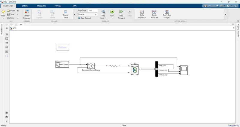
The model is shown below:
Blocks used in this simulation:
Signal builder:
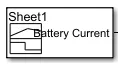
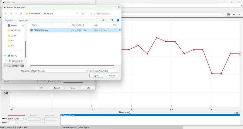
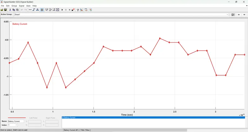
the drive cycle is imported into the signal builder block. the process is shown below.
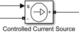
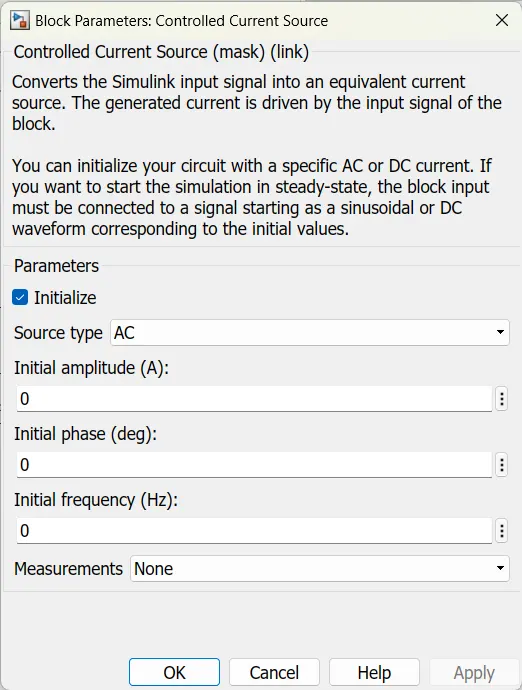
Controlled current source:
Resistor:
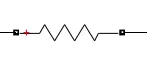
for the resistor, i'm taking the series RLC branch and selecting the resistor. the properties of the resistor are shown below.
Battery:
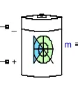
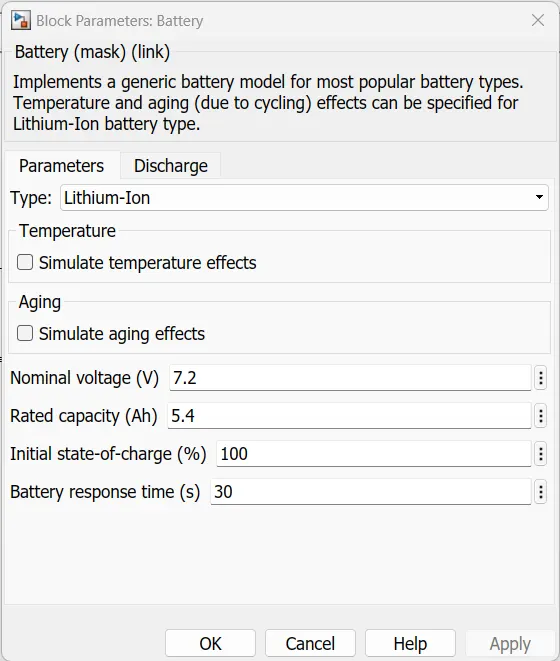
the battery with the default values is taken. the properties of battery is shown below figure.
Bus selector:
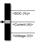
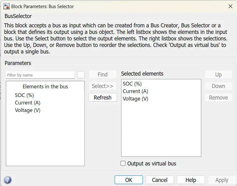
Scope:

Powergui:
Drive cycle input is shown below:
Model explanation:
In this model, the signal builder is taken as the input of the simulation. In this signal builder given drive cycle is imported and given to a controlled current source block. the controlled current source block is connected to battery. A resistor is connected between controlled current source and battery block. a bus selector block is connected to battery measurement port. In this bus selector block we choose the SOC, Current, and Voltage parameters. And these signals are given to a scope block, the signal builder block signal also given to the scope to observe the response of the model.
Results:
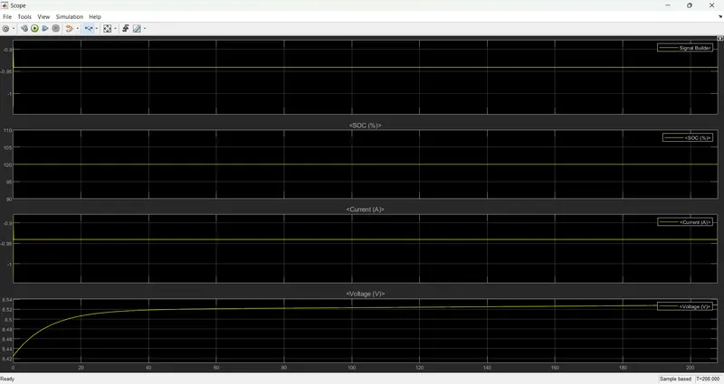
The simulation is run for 208 seconds and the battery response is observed in the below plots.
Plot:
after zooming the plot the signal is shown below:
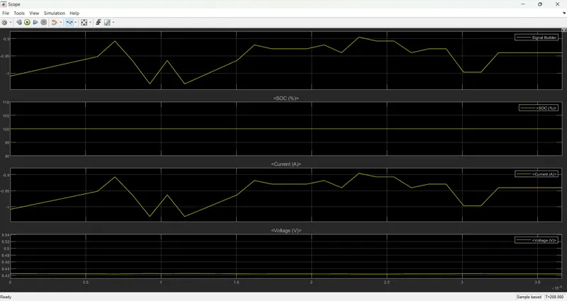
In the above plot, we can observe the drive cycle and the battery SOC are maintained at 100%.
The current signal is similar to the signal builder output signal.
The voltage is starting from 8.42 volts to 8.52 volts.
conclusion:
The maximum heat generation of the battery is calculated by using the given drive cycle. SOC of the battery model is designed in Simulink and simulated for 208 seconds. the response of the model is observed in scope.