Week-6 Challenge: EV Drivetrain
OBJECTIVE:
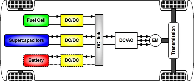
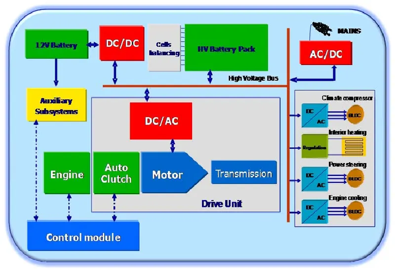
- Which power converter circuits are employed in an electric and hybrid electric vehicle?
- Electric Vehicle's powertrain with a 72V battery pack is shown in the diagram below. The duty ratio for acceleration operation is 'd1' and for the braking operation the duty ratio is 'd2'. What is EV steady-state speed if the duty cycle is 70%?
- Develop a mathematical model of a DC Motor for the equation (ω=V/Kϕ -Ra/Kϕ^2. T) using Simulink.
- Refer to the blog on the topic: Induction Versus DC brushless motors by Wally Ripple, Tesla Explain, in brief, the author’s perspective.
OBJECTIVE-1:
What is a power converter?
Power electronic technology deals with processing and controlling the flow of electrical energy in order to supply voltages and currents in a form that is optimally suited for the end user’s requirements.
A power electronic converter uses power electronic components such as SCRs, TRIACs, IGBTs, etc. to control and convert the electric power. The main aim of the converter is to produce conditioning power with respect to a certain application.
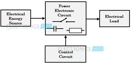
The block diagram of a power electronic converter is shown in the figure above.
It consists of an electrical energy source, a power electronic circuit, a control circuit, and an electric load. This converter changes one form of electrical energy to another form of electrical energy.
The power electronic circuit consists of both the power part and the control part. The power part transfers the energy from source to load and it consists of power electronic switches (SCR or TRIAC), transformers, electric choke, capacitors, fuses, and sometimes resistors.
The control circuit or block regulates the elements in the power part of the converter. This block is built with a complex low-power electronic circuit that consists of either analog or digital circuit assembly.
Power electronic converters perform various basic power conversion functions. This converter is a single power conversion stage that can perform any of the functions in AC and DC power conversion systems.
The type of functions performed by power electronic converters are categorized into the following types.
- AC to DC = Rectifier: It converts AC to unipolar (DC) current
- DC to AC = Inverter: It converts DC to AC of desired frequency and voltage
- DC to DC = Chopper: It converts constant to variable DC or variable DC to constant DC
- AC to AC = Cycloconverter, Matrix converter: It converts AC of the desired frequency and/or desired voltage magnitude from a line AC supply.
AC to DC Converters or Rectifiers
An AC to DC converter is also called a rectifier, which converts AC supply from main lines to DC supply for the load.
The block diagram of an AC to DC converter is shown in the figure below
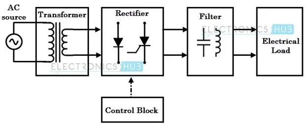
The transformer adjusts the primary AC source supply to the input of the rectifier stage. Usually, it is a step-down transformer that reduces the supply voltage to a circuit operating range. The rectifier converts the low voltage AC supply into a DC supply.
It comprises a diode and/or thyristors based on the type of rectifier. The output of the rectifier is of pulsed DC and hence it is filtered using a filter circuit, which is usually made with a capacitor or a choke.
The control block controls the firing angle of thyristors in the case of phase-controlled rectifiers. Since the diode is not a controllable device, a control block is not needed in the case of diode rectifiers.
Rectifiers are majorly classified into two types
- Uncontrolled diode rectifiers
- Controlled rectifiers
Uncontrolled Diode Rectifiers
This type of rectifier converts AC voltage from mains into a fixed DC voltage.
Since the diodes are uncontrollable components (which do not require any triggering), these converters are called uncontrolled converters as they produce a fixed voltage. The input voltage can be either single-phase or three-phase.
The diode rectifiers are classified into the following types.
1. Single-phase half-wave rectifier
2. Single-phase center-tapped full-wave rectifier
3. Single-phase full-wave bridge rectifier
4. Three-phase Half-wave diode rectifier
It employs three diodes and its anode terminals are connected to a three-phase source via transformer as shown in the figure.
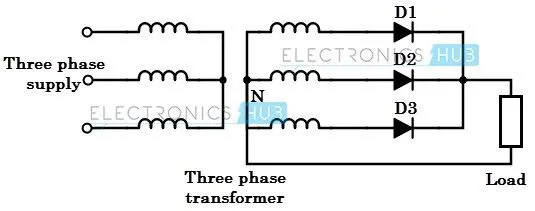
The load is connected between the common cathode point and neutral terminal of the star-connected source.
When R-phase is at its peak value, maximum conduction occurs through diode D1 as it is forward biased and no conduction takes place through it during negative alteration of phase R. During Y-phase and B-phase maximum values, the other two diodes conduct in a similar manner.
The main disadvantage of this rectifier is that the secondary winding consists of a DC component of current which can cause the transformer core to go under saturation problem.
Therefore, it is not advisable to use a three-phase half-wave rectifier for large power applications.
5. Three-phase full-wave diode bridge rectifier
This type of rectifier is suitable for high-power applications, typically the power output being higher than 15KW.
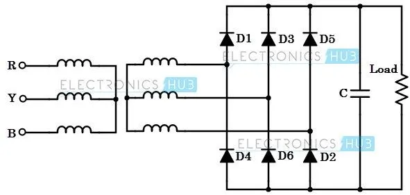
The circuit of the full-wave diode bridge rectifier is shown in the above figure.
It requires six diodes for the operation of the circuit. This type of circuit doesn’t need any neutral connection from a three-phase source therefore, a star, as well as delta-connected sources, can be used.
Here the output current flows through one diode of the upper group and one diode of lower group of diodes. If anode of a diode is at high potential, this upper group diode will conduct while other two diodes are reversed biased.
Similarly, the diode having the cathode at lower potential will conduct while other two diodes are off. The diode pair’s conduction for the above circuit is given as D6 D1, D1 D2, D2 D3, D3 D4, D4 D5, and D6 D1.
Since one diode from the upper group and one diode from the lower group are always conducting; negative members of three-phase voltages are rectified, so the output voltage consists of six segments of line voltage during one cycle.
For this reason, three-phase bridge rectifiers are called six pulse rectifiers.
These are efficient rectifiers as compared to half-wave converters. Due to six pulse output, ripple content in the output is very low, typically about 4.5%.
This avoids the additional filter circuit in many high-power applications. Even if a filter is required, a small-sized filter is enough because of an increase in ripple frequency to six times the input frequency.
Phase Controlled Rectifiers
These are similar to the uncontrolled rectifiers but the only difference is that the uncontrolled diodes are replaced by a controlled thyristor family of devices such as SCRs.
These are also called phase-controlled rectifiers. Unlike diodes, thyristors can be controlled by triggering them at desired instants in order to vary the output voltage.
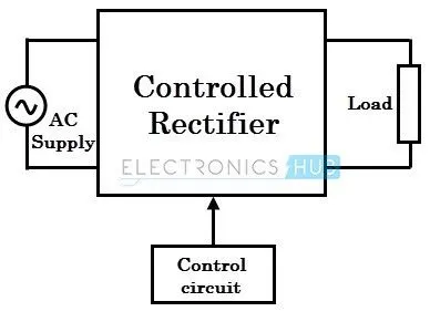
The block diagram of a controlled rectifier is shown in the above figure.
That transfers the DC power to the load in a controlled manner by varying the triggering angle of thyristors (by the control circuit) using different technologies such as a microprocessor or microcontroller-based techniques.
The start of thyristor conduction varies the average value of the output voltage of the converter. Similar to the uncontrolled rectifier types, these thyristor-based converters are also classified into the following types.
Single-phase half-wave rectifier:
In this, a single thyristor or SCR is connected between the secondary of the transformer and a resistive load as shown in the figure. The primary of the transformer is connected to a single-phase supply and considered that load is resistive.
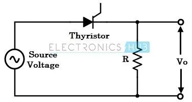
During the positive half cycle of the input AC supply, thyristor T1 is forward biassed, and when it is triggered at some firing angle through the gate terminal, it starts conducting current to the load.
Since the SCR is a unidirectional device, it turns OFF during the negative half-cycle. So the output voltage is produced only for the positive half cycle.
The output power delivered by this half-wave rectifier is controlled by phase control, i.e., varying firing angle to the gate terminal. A load of this rectifier can be an RL load and an RLE load with a freewheeling diode.
Single-phase full-wave mid-point rectifier
This converter rectifies both positive and negative half-cycles of the input supply. It uses two SCRs with a center-tapped secondary transformer as shown in the figure.
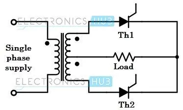
In the positive half-cycle of the input supply, thyristor T1 is forward biased while T2 is reverse biased. WhenT1 is triggered, the supply voltage appears across the load.
It conducts till 180 degrees of input supply and turns OFF due to natural commutation. During the negative half-cycle, thyristor T2 is forward biased and when it is triggered, it starts conducting. It conducts till the next positive half cycle.
The load could be RL or RLE depending on the type of application it is employed. This type of converter produces an output voltage twice that of a single-phase half-wave rectifier.
These are essential when one of the terminals on the DC side has to be grounded. However, a center-tapped transformer with a VA rating twice that of the load is required and also high voltage rating thyristors are needed in this converter.
Single-phase full-wave bridge rectifier
The circuit diagram of a full-wave bridge rectifier using thyristors is shown in the figure below. It consists of four SCRs which are connected between a single-phase AC supply and a load.
This rectifier produces controllable DC by varying conduction of all SCRs.
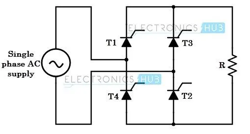
In the positive half-cycle of the input, thyristors T1 and T2 are forward biased while T3 and T4 are reverse biased. Thyristors T1 and T2 are triggered simultaneously at some firing angle in the positive half cycle, and T3 and T4 are triggered in the negative half cycle.
The load current starts flowing through them when they are in a conduction state. The load for this converter can be RL or RLE depending on the application.
By varying the conduction of each thyristor in the bridge, the average output of this converter gets controlled. The average value of the output voltage is twice that of a half-wave rectifier.
Three-phase half-wave converter
The output from a single-phase converter is small; when high power is required, three-phase rectifiers are used. A three-phase half-wave rectifier with thyristors is shown in the figure below.
The three-phase supply is given to this converter through a three-phase transformer with the star-connected secondary.
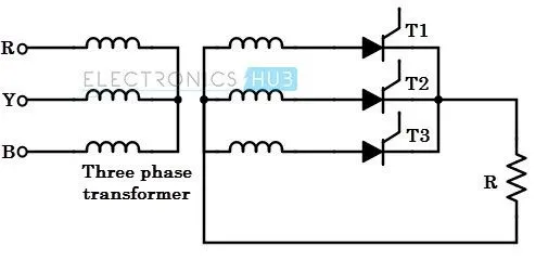
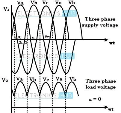
It works similar to the three-phase diode bridge rectifier. In this, thyristor T1 is at the highest positive anode voltage in the interval π/6 to 5π/6. During this interval, T1 can be made to conduct by giving a firing pulse to its gate.
This thyristor T1 continues to conduct till thyristor T2 is made to conduct in the interval 5π/6 < wt < 3π/2. Now the load current starts flowing through T2. Similarly, thyristor T3 is starts conducting once thyristor T2 is turned OFF.
In this, there are three pulses of output voltage during each complete cycle of the supply voltage. Thus, the ripple frequency is three times the supply frequency.
For this reason, this converter is also called a 3-pulse converter. This converter can be connected to different loads such as RL and RLE loads.
Three-phase full-wave converter
It is obtained by connecting a DC terminal of two three-pulse converters in series. It is also called a 6-pulse bridge converter. This type of converter is used in industrial applications where two-quadrant operation is required.
Here the load is connected via a three-phase half-wave connection to one of three supply lines. Thus, there is no need for a transformer; however, for isolation purposes, a transformer is connected as shown in the figure.
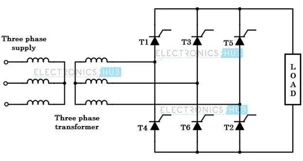
Here thyristors T1, T3, and T5 forms a positive group, whereas thyristors T4, T6, and T2 forms a negative group. And thus, positive group SCRs are turned ON for positive supply voltage and negative group thyristors are turned ON for negative supply voltages.
In this, one of the thyristors from the positive, whose anode voltage is maximum positive will conduct at any instant, and simultaneously one of the thyristors from the negative group, whose cathode voltage is maximum negative will conduct.
This converter can be connected to RL or RLE loads. By controlling the firing angle to the respective thyristor, the average power delivered to the load is changed.
The firing angle of a particular thyristor in a positive group is measured from the instant when its anode becomes maximum positive.
Similarly, the firing angle for a thyristor in the negative group is measured from the instant when its cathode terminal attains a maximum negative value.
DC to DC Converters
Many DC-operated applications need different levels of DC voltage from a fixed DC source.
Some of these applications include subway cars, DC traction systems, control of large DC motors, battery-operated vehicles, trolley buses, etc. They require variable DC to produce variable speed, so a power conversion device is needed.
A DC chopper is a static device that converts a fixed input DC voltage to variable DC output or a fixed DC output of a different magnitude (which can be lower or higher) than the input value. The block diagram of a DC chopper is shown in the figure below.
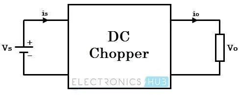
The chopper circuit is connected between the DC input source and DC load. This chopper consists of power electronic switching devices such as thyristors which are connected in such a way that they produce the required DC voltage to the load.
The output voltage is controlled by adjusting the ON time of the thyristor (or switch) which in turn changes the width of the DC voltage pulse at the output. This method of switching is called pulse width modulation (PWM) control.
The output of the chopper can be less or greater than the input and also it can be fixed or variable. These can be unidirectional or bidirectional devices based on the application it is intended for.
DC choppers are mainly used in DC drives, i.e., electric vehicles and hybrid electric vehicles.
DC choppers are classified into three basic types based on input and output voltage levels and are discussed below.
Step-down Chopper or Buck converter
A step-down chopper produces an average output voltage lower than the input DC voltage. The circuit for this converter is shown in the figure below.
Here the switching component is a thyristor that switches the input voltage to the load when it is triggered at particular instants.
A diode acts as a free-wheeling diode that allows the load current to flow through it when the thyristor is turned OFF. If this diode is absent, a high induced EMF in inductance may cause damage to the switching device.
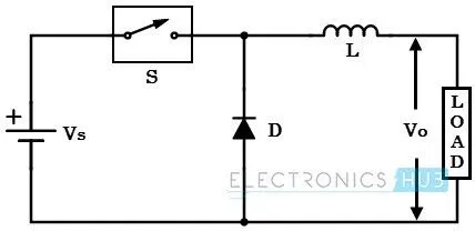
The average output voltage of the converter is varied by controlling the turn ON/OFF periods of the thyristor. When the thyristor is turned ON, the output voltage is the same as the input voltage and if it is turned OFF, the output voltage is zero.
The output voltage is equal to (TON / T) Vin. So, by controlling the duty ratio K = (TON / T), the output voltage will be increased.
Step-up Chopper or Boost converter
In this chopper, the output voltage is always greater than the input voltage. The configuration of a boost converter is shown in the figure below.
Here also a switch is used, which is connected in parallel with the load. This switch is a thyristor or an SCR.
Similar to the buck converter, a diode is placed in series with the load that allows the load current to flow when the thyristor is turned OFF.
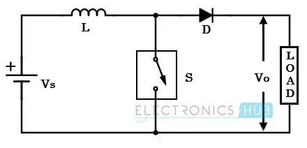
When the thyristor is turned ON, the diode is reverse-biased and hence it isolates the load circuit from the source. So the inductor charges to the maximum input voltage source.
When the thyristor is turned OFF, the load gets the voltage from the input as well as from the inductor. So the voltage appearing across the converter output will be more than the input.
Here the output voltage is equal to (1/ 1 – d) times the input voltage, where d is the duty ratio (TON / T). By varying this duty ratio, the output voltage will be varied till the load gets desired voltage.
Buck/Boost converter
This chopper can be used both in step-down and step-up modes by continuously adjusting its duty cycle. The configuration of the buck-boost converter is shown in the figure below that consists of only one switching device, i.e., one thyristor.
Along with an inductor and diode, the additional capacitor is connected in parallel with this circuit.
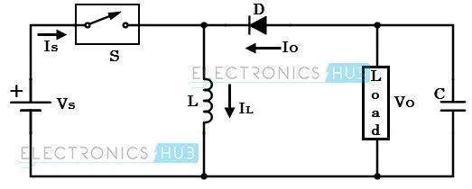
When the thyristor is turned ON, the supply current flows to the inductor through the thyristor and induces the voltage in the inductor.
When the thyristor is OFF, the current in the inductor tends to decrease with the induced emf reversing polarity. The output voltage of this converter remains constant as the capacitor is connected across the load.
By varying the value of duty ratio to a certain value, the output voltage is lower than the input voltage, typically in the range 0 ≥ k > 0.5, thus a buck converter.
And the output is higher than the input voltage if the duty ratio is in the range of 0.5 > K ≥ 1, thus acting as a boost converter.
AC to AC Converters
AC/AC converters connect an AC source to AC loads by controlling the amount of power supplied to the load. This converter converts the AC voltage from one level to the other by varying its magnitude as well as the frequency of the supply voltage.
These are used in different types of applications including uninterrupted power supplies, high power AC to AC transmission, adjustable speed drives, renewable energy conversion systems, and aircraft converter systems.
The types of AC-to-AC converters are discussed below.
AC/AC Voltage Converters
These converters control the RMS value of output voltage at a constant frequency. The common application of these converters includes starting AC motors and controlling power to heaters.
A single-phase AC/AC voltage converter consists of a pair of anti-parallel thyristors along with a control circuit as shown in the figure below.
The other names of this controller are single-phase full-wave converter and AC voltage controller.
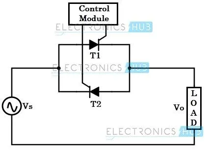
During the positive half cycle of the input signal, thyristor-1 is forward biased and it starts conducting when the triggering is applied. Thus the power flows from source to load.
In the negative half cycle of the input, thyristor-2 is forward biased and starts conducting when it is triggered, while thyristor-1 is turned OFF by natural commutation.
By varying the triggering or conduction angle of each thyristor during each half-cycle, the magnitude of the voltage appearing across the load is controlled.
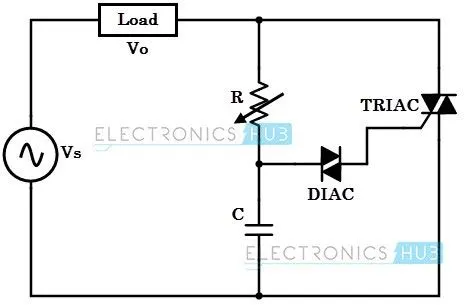
The other popular form of AC voltage controller is the use of TRIAC in place of two anti-parallel thyristors. The figure below shows TRIAC based AC controller along with a triggering control circuit.
Here diac controls the positive and negative triggering to the TRIAC so that the average output voltage to the load is controlled.
AC/AC Frequency Converters
These converters are mainly used for varying the frequency of the input source to desired level of the load. An AC/AC frequency converter changes the frequency of input voltage/current of the load compared to the frequency of the source.
Some of these converters may control the magnitude of voltage besides the frequency control. These are mainly used for adjusting the speed of AC drives and also for induction heating.
The two major classes of these converters include
1. Cyclo converters
and
- Matrix converters.
Matrix Converter
Since the cyclo-converters satisfactorily work only for a certain range of frequencies, matrix converters are invented that have unrestricted frequency conversion capability.
These are constructed using full-controlled static devices, and mostly use bidirectional switches. With the use of these switches in three-phase matrix converters, any phase of the load can be connected to any phase of the input supply.
By using pulse width modulation techniques, the load frequency and voltages are controlled from zero values to their maximum values.
DC to AC Converters or Inverters
These converters are connected between the DC source of fixed input and variable AC load. Most commonly, these DC to AC converters is called inverters. An inverter is a static device that converts fixed DC supply voltage to variable AC voltage.
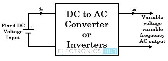
Here the fixed DC voltage is obtained from batteries or by DC link in most power electronic converters. The output of the inverter can be variable/ fixed AC voltage with variable/fixed frequency.
This conversion from DC to AC along with variable supply is produced by varying the triggering angle to the thyristors. Most of the thyristors used in inverters are employed with the forced commutation technique.
These can be single-phase or three-phase inverters depending on the supply voltage. These converters are mainly divided into two groups. One is PWM-based inverters and the other is multilevel inverters.
Further, these are classified as voltage source inverters and current source inverters. Each type is subdivided into different types such as PWM, SVPWM, etc. Multilevel inverters are more popular in industrial applications.
OBJECTIVE-2:
In this challenge, we have to find the Steady-state speed of the vehicle at 70% duty cycle.
Solution:
Given Data:
Motor and Controller Parameters:
Rated Armature voltage= 72 V
Rated armature current= 400 A
Ra= 0.5Ω, KΦ= 0.7 Volt second
Chopper Switching frequency= 400 Hz
Duty cycle = 70% =0.7
Actual voltage = battery voltage x duty cycle
= 72 x 0.7
= 50.4 v
Dc motor torque equation is
`"T=" (Vk∅)/R_a -((k∅)^2/R_a ) .ω`
`"T=" (50.4 x 0.7)/0.5-((0.7)^2/0.5) .ω`
`"T= " 70.56-0.98 .ω --------(1)`
`"T= " 24.7+(0.0051) .ω^2 -------------(2)`
Comparing the equations 1 and 2 we get
`70.56-0.98 .ω "= " 24.7+(0.0051).ω^2`
`〖0.0051.ω〗^2+0.98ω-45.8 "=0"`-------(3)
solving the equation (3) by quadratic equation we get the below values
`ω=38.91 rad/sec`
`ω=-231 rad/sec`
The steady-state speed of EV at 70% of duty cycle is 38.91 rad/sec in rpm 371rpm
OBJECTIVE-3:
Developing a mathematical model of DC Motor using Simulink,
The equation is
ω = V/Kϕ - Ra/Kϕ^2 .T
Inputs for the equation are,
V= 72v, Kϕ=0.7, Ra= 0.05
for the torque, ramp signal block is taken.
A simulation of the above equation is shown in the below figure.
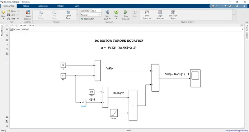
After running the simulation for 10sec, the plot will generate according to the input values.
the plot is shown in the below figure.
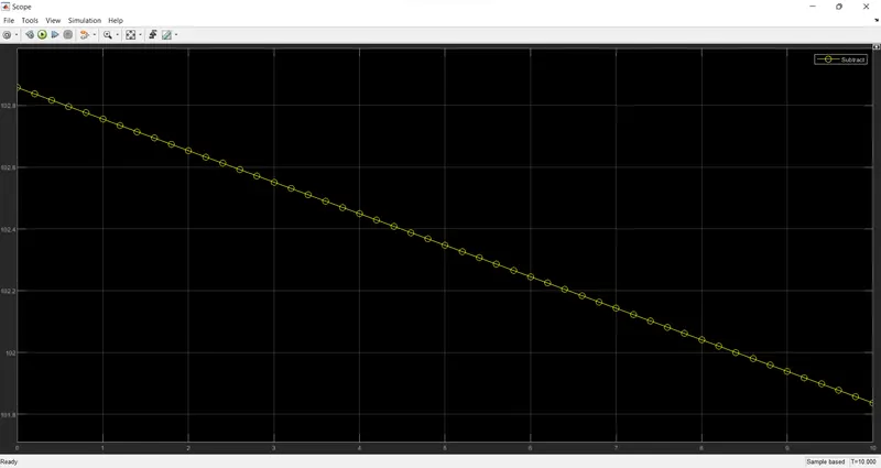
In this plot time is taken on X-axis and torque is taken on Y-axis.
OBJECTIVE-4:
The Author Wally Ripple Prior to joining Tesla Motors, he was an engineer at AeroVironment, where he helped develop the EV1 for General Motors. and was featured in the documentary movie, Who Killed the Electric Car? Wally has also worked for the Jet Propulsion Laboratory on electric vehicle battery research, among other projects. In 1968, as a Caltech undergraduate student, he built an electric car (a converted 1958 Volkswagen microbus) and won the Great Transcontinental Electric Car Race against MIT.
In this blog, he explains Induction motors, and Dc brushless motors of the differences, advantages, and limitations. Later he compared the previous and the upcoming era based on his experience.
In this article author clearly said that not only one engine is best, every engine has its own specifications and requirements based on its usage. In the earlier days, Lead Acid is used but nowadays Lithium is used in batteries. As well as Dc motors are replaced by Dc Brushless motors and Induction Motors.
Then he Discusses Dc brushless motors and Induction motors. In the Dc brushless machines, Permanent magnets are used to generate the dc magnetic field. But the Induction motor has Steel laminations with buried peripheral conductors that form a shorted structure. As the rotor rotates in dc machines the magnitude and polarity of the stator currents be continuously varied, the torque remains constant and the conversion of electrical to mechanical energy is optimally efficient. The dc brushless motors required the current control device called Inverter, without this device dc brushless motors are useless. For the Induction motors Inverter devices are not required.
Then he explained about three-phase induction motors and brushless motors. Both of these motors are identical with differences in the rotor. When a three-phase induction motor is connected to utility type three-phase power, torque is produced at the outset; the motor has the ability to start under load. No inverter is needed. The Dc brushless motor produces no starting torque when directly connected to fixed frequency utility power, and then they need an inverter to maintain in step with the angular position of the rotor.
Three-phase induction motors cannot operate from DC. Ac is must required this is the limitation of a three-phase induction motor. Adding an inverter to the induction motor and then it becomes possible to provide power from the Dc source or battery.
Then he said in 1990 all the EVs except one were powered by DC brushless drives. Today, all the hybrids are powered by DC brushless drives, with no exceptions. Later he discusses the control code and then the main difference in the DC brushless drive is producing less rotor heat. The DC brushless drive can also operate at a unity power factor, whereas the best power factor for the induction drive is about 85%. This means the dc brushless drive efficiency is higher than the induction drive.
Then he discussed the ideal brushless drive permanent magnets (PM) strength of the magnetic field, the handling of PMs, and then its cost effect on the machine. He discussed losses, the magnetic field produced by the permanent magnets is adjustable due to this eddy, and hysteresis and i^2 losses are minimized. Unfortunately, there is no easy way of changing B with permanent magnets. In the Induction motors, magnets are not presented so the field value can be adjustable and the losses are reduced, efficiency will increase.
The author concludes DC Brushless drives will likely continue to dominate in the hybrid and coming plug-in hybrid. The Induction drives maintain dominance or the higher performance pure electrics. The hardware of both the induction and Brushless dc drive is the same. In the future, we can see the Brushless DC Motors and Induction motors work side by side in the hybrid and electric vehicles.