Project 1 (Mini Project on Vehicle Direction Detection
Answer:
Aim:
- The Main Aim of this project is to create a Model Based Development of a Simulink Model for Vehicle Direction Detection as per the Requirements specified.
- Requirement tagging for Requirement 1 & Requirement 2 subsystems in the Simulink model with the respective selection in word document.
- Create a Simulink Data Dictionary and linking to the Developed Simulink Model.
- Generate C code by using Embedded coder for Developed Simulink Model.
Introduction:
Identifying the direction of the vehicle is one the important & diverse features in Autonomous driving & Advanced Driver Assistance Features. This particular sub-feature of identifying the direction of vehicle is basically identifying the direction the vehicle is taking based on the camera input.
Camera reads the road signs & stores into its memory with unique values for left turn, right turn & straight drive. Depending on the direction it is taking, final indication is given to the driver – as an indication if he is driving in the recommended direction or not.
Vehicle Direction Determination can also be coupled along side features like GPS systems to identify whether the vehicle is reaching its destination in an optimized manner. This sub feature can also be used along with Lane Detection, Highway Warning, Ramp Entry / Exit in Wrong way Detection etc.
Objective:
- Development of MATLAB Simulink model as per Requirement.
- Tag the requirements to the Simulink model, tagging requirement 1 & requirement 2 to their corresponding subsystems is fine.
- For code generation, storage class for input signals; ImportedExtern; Storage class for output signals: Export to file; Storage class for local signals; localizable; Storage class for calibration signals: Const.
- Sample time for all signals as 0.01s.
Requirement-1:
- Steering wheel input as yaw rate (Signal name: SteeringWheel_YawDegreeInput) is the input for this system.
- This is compared against 3 angular values, one each for left turn, right turn & straight drive (Calibration Values: Right_Turn_AngularLimit, Left_Turn_AngularLimit, Straight_Drive_Steering_Angle) to say which specific direction the steering wheel is turning towards.
- Use switch blocks to compare & develop this requirement. Keep this requirement in a subsystem & output of this requirement is a local signal (Signal Name: Vehicle_Turn_Status).
Requirement -2:
- Keep this requirement as a separate subsystem. Inputs to this requirement are local signal from requirement 1 (Signal Name: Vehicle_Turn_Status) & an input signal from camera (Signal Name: Camerainput_RoadSign), which confirms the occurrence of a road sign.
- Signal Vehicle_Turn_Status is compared against calibration values (Calibrationn Values: RightTurn_RoadSign, LeftTurnn_RoadSign, Straight_RoadSign), if each of them is found equal, the each of the three corresponding output is copared against the camera input signal.
- Using a logical operator block, only one among them is finally given as output signal (Signal Name: Vehicle_Direction_Indicator).
SIMULINK MODEL DEVELOPMENT:
The main subsystem ‘Vehicle_Direction’ along with inputs ‘SteeringWheel_YawDe’reeInput', ‘CameraInput_RoadSign’ and output signal ‘Vehicle_Direction_Indicator’ is shown below:
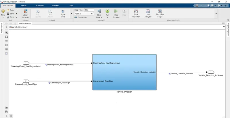
Vehicle_Direction subsystem:
The main subsystem’Vehicle_Direction’ is further divided into two more subsystems which are ‘Requirement1’ and ‘Requirement2’ as shown below:
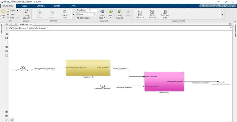
Requirement 1:
- In the Requirement 1 subsystem, the steering wheel yaw degree (Signal name: SteeringWheel_YawDegreeInput) is given as input to the subsystem.
- This input value is compared with 3 angular values, one each for left turn, right turn & straight drive (Calibration values: Right_Turn_AngularLimit, Left_Turn_AngularLimit, Straight_Drive_Steering_Angle) to say which specific direction the steering wheel is turning towards.
- The input signal ‘SteeringWheel_YawDegreeInput’ is compared against three angular values using the relational operators ‘==’, one each for left turn, right turn & straight drive (Calibration values: Right_Turn_AngularLimit, Left_Turn_AngularLimit,Straight_Drive_Steering_Angle) to say which specific direction the steering wheel is turning towards.
- In this case, the output of the relational operator ‘==’ is equal to ‘1’ only when the ‘SteeringWheel_YawDegreeInput’ matches the calibration value angular limit specified in Right_Turn_AngularLimit, Left_Turn_AngularLimit, or Straight_Drive_Steering_Angle.
- The Three switch blocks are used to implement an if-else logic. The output from each relational operator is given as a condition input ( input2) to each Switch block.
- The switch will pass input1 when the condition (Input2=0) is satisfied, else input3 is passed as output.
- Vehicle_Turn_Status signal is obtained at the output of the first switch will be a calibration angular value (Right_Turn_AngularLimit, Left_Turn_AngularLimit,Straight_Drive_Steering_Angle). If none of the conditions get satisfied, zero is passed as the output from the last switch. The signal ‘vehicle_Turn_Status’ is fed to the outport of subsystem ‘Requirement 1’.
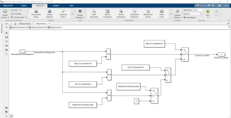
Requirement 2:
- In ‘Requirement 2’ subsystem, the local signal ‘Vehicle_turn_Status’ fed from ‘Requirement 1’ subsystem is taken as input and is compared against calibration vlues (RightTurn_RoadSign,LeftTurn_RoadSign, Straight_RoadSign) using the relational operator ‘==’.
- The Boolean value obtained at the output of the relational operator is compared against a Boolean input signal from camera (Signal Name: CameraInput_RoadSign), Which confirms the occurrence of a road sign using ‘AND’ operator.
- The Boolean output signal obtained from each of the three ‘AND’ blocks are fed to the outport ‘Vehicle_Direction_Indicator’ to indicate the vehicle direction. The output ‘Vehicle_Directionn_Indicator’ will be a three dimension signal having three Boolean elements, with the first element to indicate ‘Right Turn’, second element to indicate ‘Left Turn’ and third element to indicate ‘Straight Drive’.
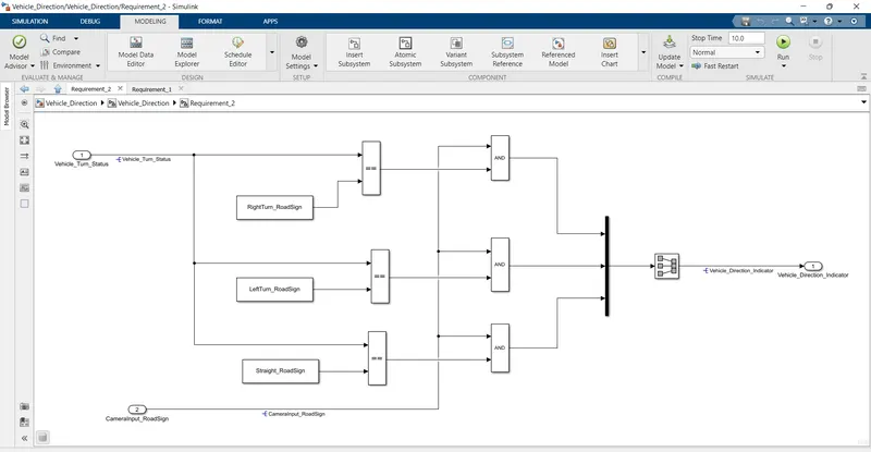
Requirements tagging to subsystems:
The requirements ‘Requirement 1’ and ‘Requirement 2’ as provided in the Requirements word document are tagged to their corresponding subsystem in the Simulink model.
The steps involved in tagging a requirement in the Simulink model is to ffirst highlight the requirement statement in the word document, then right click on the subsystem in the model that has to be tagged, then select ‘Requirements’ and then ‘Link to Selection in Word’.
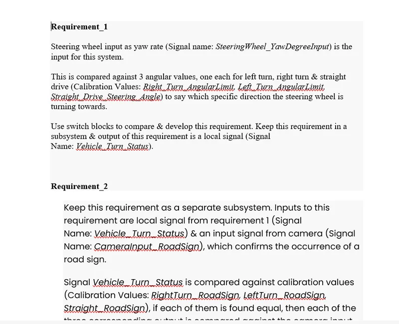
Requirement-1 Taging to subsystem:
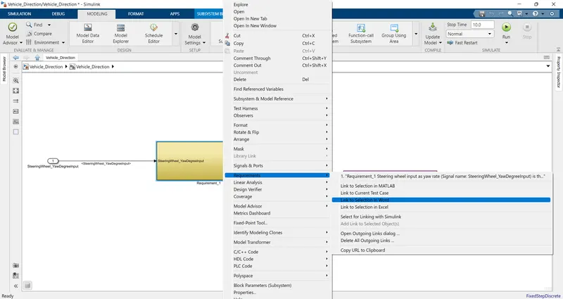
Requirement-2 Taging to subsystem:
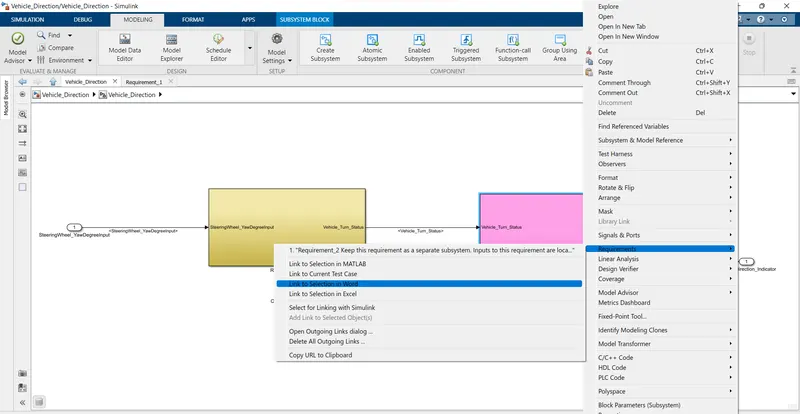
Simulink Data Dictionary File Creation:
First open the Simulink window and then go to the modelling window then select link to data dictionary.
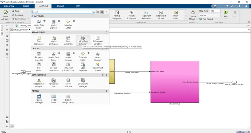
Then model properties window is open then select new and check box Enable model access to base workspace and click apply and ok as shown in below.
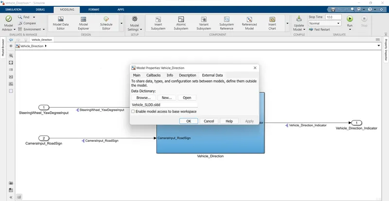
After creating the Simulink data dictionary file, open the model explorer and select the sldd file.
Add all signals and constants as given in input data.
- Storage class for input signals: ImportedExtern; Storage class for Output signal: Export to File; Storage class for local signals: Localizable; Storage class for calibration signals:
- Choose sample time for all signals as 0.01s.
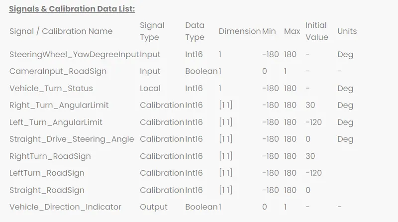
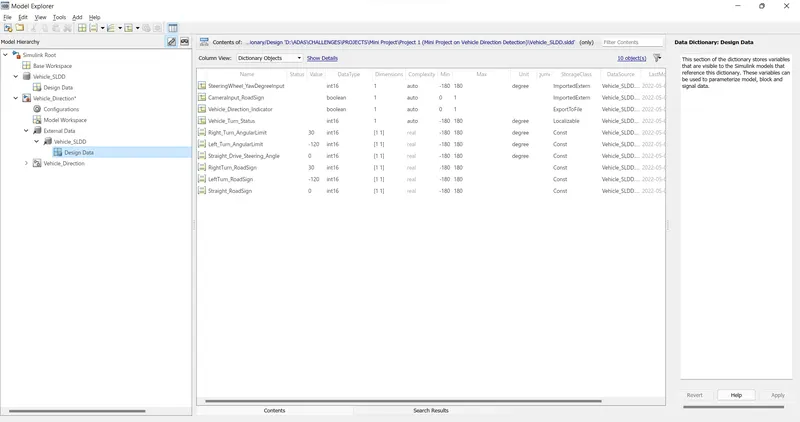
Solver and code Generation settings:
In the solver settings change the type to variable to fixed step and sovler is discreate and no continous
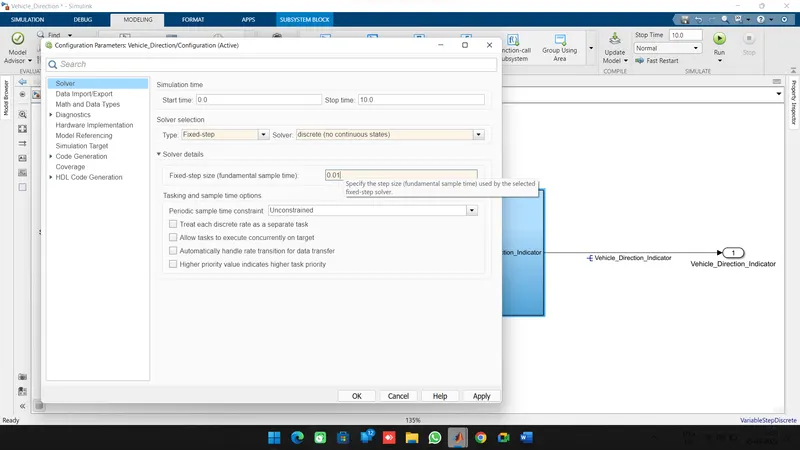
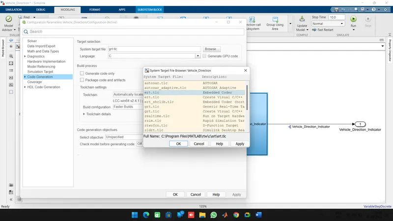
For code generation change the system target file to ert.tlc and embedded coder.
MAAB Guidelines Check in Model Advisor:
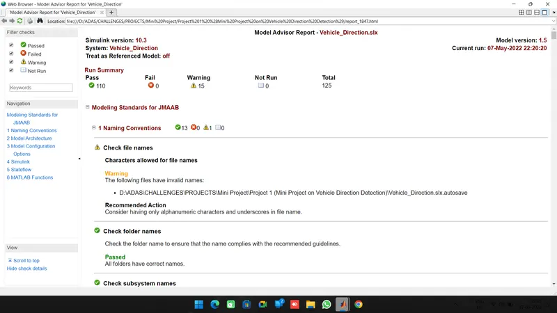
By using Model Advisor tool a check is performed to know the developed model meet the standards for MAAB.
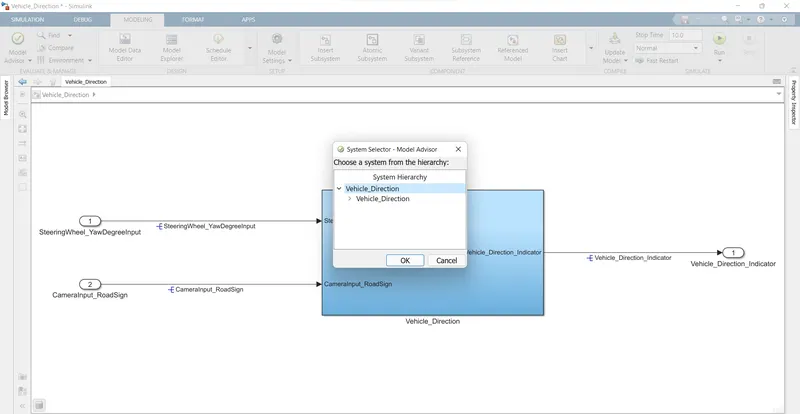
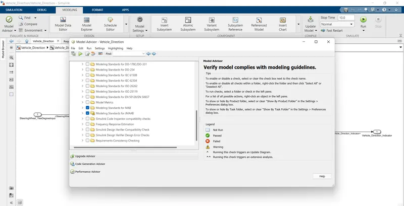
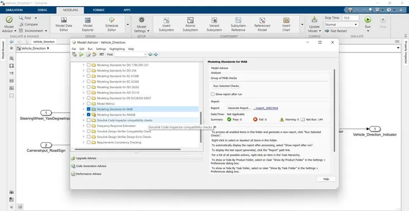
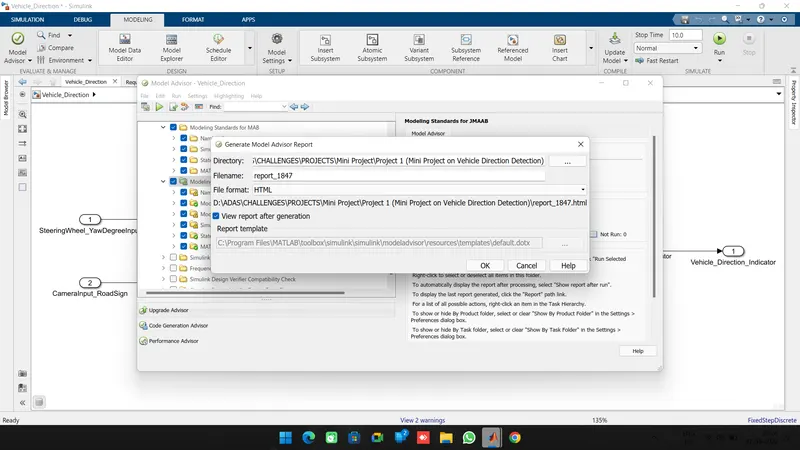
After completion of model advisor checking click on GENERATE REOPRT. an html file will be generated is shown below.
Code generation:
for code generation go to app tab and select embedded coder for c code generation.
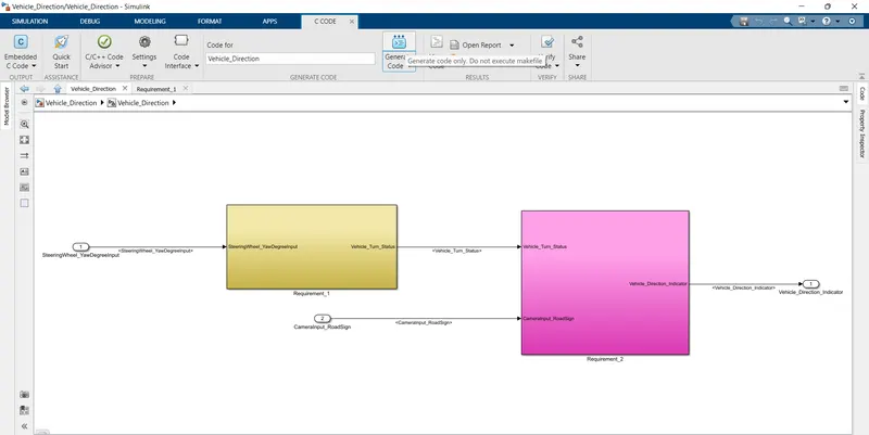
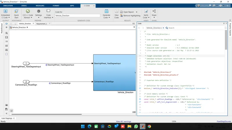
after selecting the code generation c code is generated and new tab will be open is show below.
/*
2	 * File: ert_main.c
3	 *
4	 * Code generated for Simulink model 'Vehicle_Direction'.
5	 *
6	 * Model version                  : 1.5
7	 * Simulink Coder version         : 9.5 (R2021a) 14-Nov-2020
8	 * C/C++ source code generated on : Sat May  7 22:27:11 2022
9	 *
10	 * Target selection: ert.tlc
11	 * Embedded hardware selection: Intel->x86-64 (Windows64)
12	 * Code generation objectives: Unspecified
13	 * Validation result: Not run
14	 */
15
16	#include <stddef.h>
17	#include <stdio.h>              /* This ert_main.c example uses printf/fflush */
18	#include "Vehicle_Direction.h"         /* Model's header file */
19	#include "rtwtypes.h"
20
21	/*
22	 * Associating rt_OneStep with a real-time clock or interrupt service routine
23	 * is what makes the generated code "real-time".  The function rt_OneStep is
24	 * always associated with the base rate of the model.  Subrates are managed
25	 * by the base rate from inside the generated code.  Enabling/disabling
26	 * interrupts and floating point context switches are target specific.  This
27	 * example code indicates where these should take place relative to executing
28	 * the generated code step function.  Overrun behavior should be tailored to
29	 * your application needs.  This example simply sets an error status in the
30	 * real-time model and returns from rt_OneStep.
31	 */
32	void rt_OneStep(void);
33	void rt_OneStep(void)
34	{
35	  static boolean_T OverrunFlag = false;
36
37	  /* Disable interrupts here */
38
39	  /* Check for overrun */
40	  if (OverrunFlag) {
41	    rtmSetErrorStatus(Vehicle_Direction_M, "Overrun");
42	    return;
43	  }
44
45	  OverrunFlag = true;
46
47	  /* Save FPU context here (if necessary) */
48	  /* Re-enable timer or interrupt here */
49	  /* Set model inputs here */
50
51	  /* Step the model */
52	  Vehicle_Direction_step();
53
54	  /* Get model outputs here */
55
56	  /* Indicate task complete */
57	  OverrunFlag = false;
58
59	  /* Disable interrupts here */
60	  /* Restore FPU context here (if necessary) */
61	  /* Enable interrupts here */
62	}
63
64	/*
65	 * The example "main" function illustrates what is required by your
66	 * application code to initialize, execute, and terminate the generated code.
67	 * Attaching rt_OneStep to a real-time clock is target specific.  This example
68	 * illustrates how you do this relative to initializing the model.
69	 */
70	int_T main(int_T argc, const char *argv[])
71	{
72	  /* Unused arguments */
73	  (void)(argc);
74	  (void)(argv);
75
76	  /* Initialize model */
77	  Vehicle_Direction_initialize();
78
79	  /* Attach rt_OneStep to a timer or interrupt service routine with
80	   * period 0.01 seconds (the model's base sample time) here.  The
81	   * call syntax for rt_OneStep is
82	   *
83	   *  rt_OneStep();
84	   */
85	  printf("Warning: The simulation will run forever. "
86	         "Generated ERT main won't simulate model step behavior. "
87	         "To change this behavior select the 'MAT-file logging' option.\n");
88	  fflush((NULL));
89	  while (rtmGetErrorStatus(Vehicle_Direction_M) == (NULL)) {
90	    /*  Perform other application tasks here */
91	  }
92
93	  /* Disable rt_OneStep() here */
94
95	  /* Terminate model */
96	  Vehicle_Direction_terminate();
97	  return 0;
98	}
99
100	/*
101	 * File trailer for generated code.
102	 *
103	 * [EOF]
104	 */
105
Results:
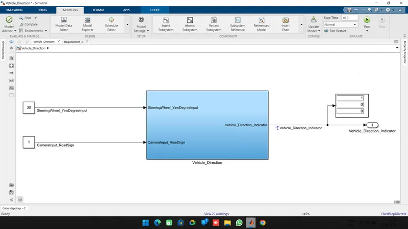
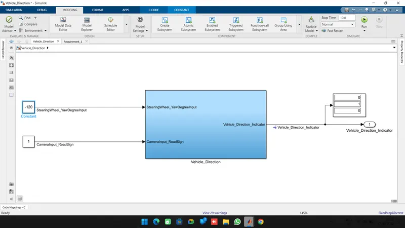
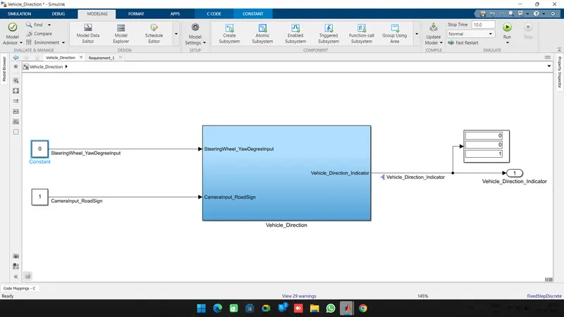
for the SteeringWheel_YawDegreeInput new constant block is replaced with constant block and input is defined based on right, left and straight drive values.
for the CameraInput_RoadSign input signal inport block is replaced with constant block and value is assigned as 1 or 0.
A display block is connected at outport block to view the output of the vehicle direction detection.
for right turn input is given as 30:
for the Left turn input is given as -120:
for the Straight drive input is given as 0:
Conclusion:
A simulink model for vehicle direction detection is developed based on given requirements 1 & 2. and simulink data dictionary file is created and attached to simulink model. This model is verifyed and reached MAAB guidlines requirements. C code is generated for this model.
Note: Simulink model file, SLDD, C Code file and required files are attaching in a zip file and uploaded.