Project 2
1. Design a Warehouse Building located in Chennai using STAAD Pro Connect Edition. The specification must be as follows:
|
Width |
30m |
|
Length |
50m |
|
Eave Height |
9m |
|
Bay spacing |
6m |
|
Soil type |
Medium |
|
Safe Bearing Capacity |
200 kN/m2 |
|
Roof slope |
1 in 12 |
Assume suitable sections for structural elements. Follow IS800:2007, IS1893 and IS 875
- Prepare a Design Basis Report for the project
- Create structural model using STAAD Pro Connect Edition
- Prepare DL, LL, WL and EQL load calculations as per IS 875 standards
- Design using MS – Excel
- Steel column
- Rafter
- Base plate
- Pedestal
- Z- purlin
- Design Foundations using STAAD Foundation.
- Attach necessary sketches and drawings wherever required.
- All stipulations, assumptions and design parameter must adhere to Indian Standards.
AIM:
Designed a warehouse located in Chennai using STAAD Pro Connect Edition. And prepare design-basis report, design of foundation
PROCEDURE:
Creating Modal
- Open STAAD.Pro CONNECT Edition Software
- Go to New option left side on the home interface
- Specify the file name, location, unit and modal type
- Click on Create, modal user interface will open
- Now, I can create beam in geometry
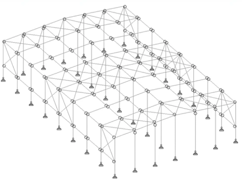
Define Property of Structure
- Goto Properties tab, click on Define
- Give property to all the sections.
- Create beta angle for wind column
- Go to material and add property as steel.
- Go to specification and add release moment for wind column.
- Create support as pinned.
Adding Load and Load Case
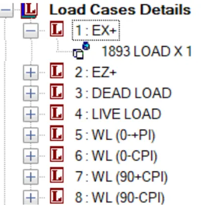
- Add Load case detail
- Ex and Ez
- Dead load and Live load
- Wind load (0+Cpi),
- (0-Cpi)
- (90+Cpi)
- (90-Cpi)
Load Combination
- Go to Analyse and add Perform analysis
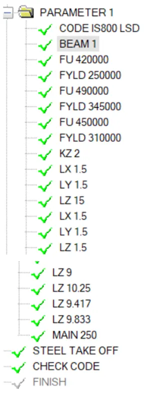
- Go to Design
- Select IS code 800
- Add Parameters
- Beam 1
- Kx,ky,kz,Lx,ly,lz
- Add check code
Results
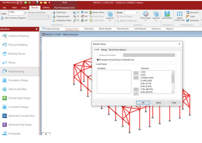
Now go to post processing
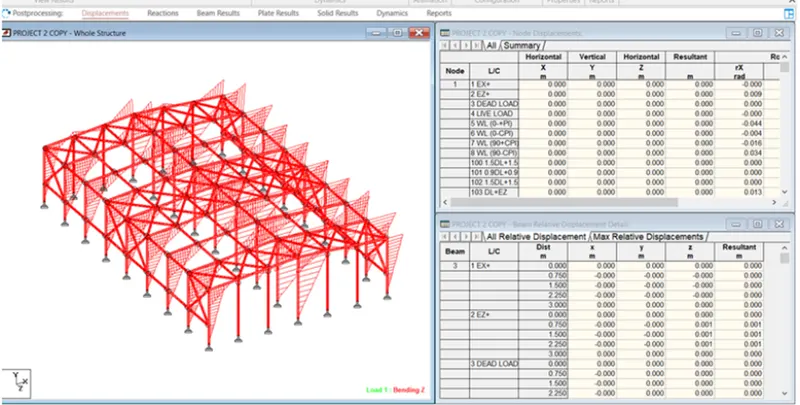
Design of foundation
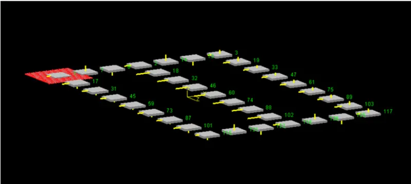
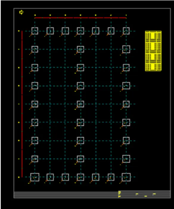
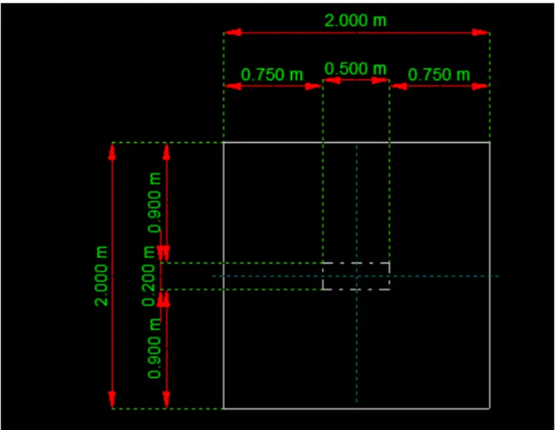
Import the modelled file in staad foundation.
Design of foundation calculation excel file are attached
Design Basis Report are attached
2. Design a simply supported gantry girder to carry electric overhead travelling crane
Given:
Span of gantry girder = 7 m
Span of crane girder = 9 m
Crane capacity = 250 kN
Self-weight of trolley, hook, electric motor etc. = 40 kN
Self-weight of crane girder excluding trolley = 100 kN
Minimum hook approach = 1.0 m
Distance between wheels = 3 m
Self-weight of rails = 0.2 kN/m
Aim : Design a simply supported gantry girder to carry electric overhead travelling crane.
The Design of simply supported gantry girder to carry electric overhead travelling crane calculation sheet added