Project 2
BACKGROUND, TECHNICAL SPECIFICATIONS, AND ASSUMPTIONS
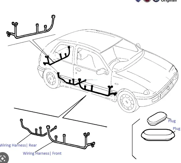
Here are a few examples of real-world examples that were taken into account when constructing the wiring harness for this project.
To perform this job, the following industry best practices and regulations regarding wiring harness packaging must be adhered to:-
- When designing the wiring harness, ease of manufacture, installation, removal, and maintenance must be taken into account.
- Avoid routing through tiny structural holes or apertures to reduce handling and chaffing during installation.
- When assembling or servicing a harness, avoid routing and clipping in regions that are difficult to access or in the blind zone.
- If more slack is required due to the environment or the harness bending requirement, give it. Slack values between 1 and 5 percent are used for this project.
- Protect the harness by avoiding routing it close to edges with sharp edges.
- The wire harness should be simple to install and remove.
- To avoid paying extra for specialized mounting solutions, clips and clamps for the wiring harness should be widely accessible on the market.
- A minimum of 25mm should be left between the clip and the branch point.
- There should be at least 50mm between the two branch locations as a minimum.
- When designing the wiring harness in the CAD environment, it should be ensured that there are no instances of fouling. To prevent fouling, additional clips or clamps may be employed.
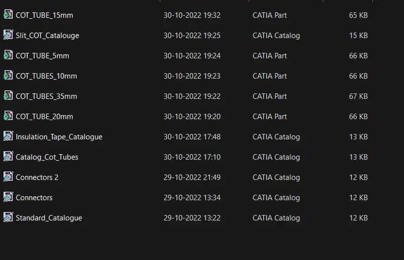
Catalog Created for protective Tubes-
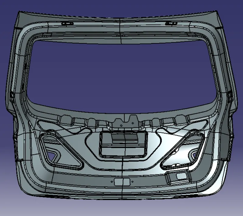
STEP 1 - DOWNLOAD THE BACK DOOR ASSEMBLY
STEP 2- SELECTING CONNECTORS AND SUPPORT CLIPS
Here we use three connectors which are mentioned below:
- C-776438 - Inline Connector (12 pole connector).
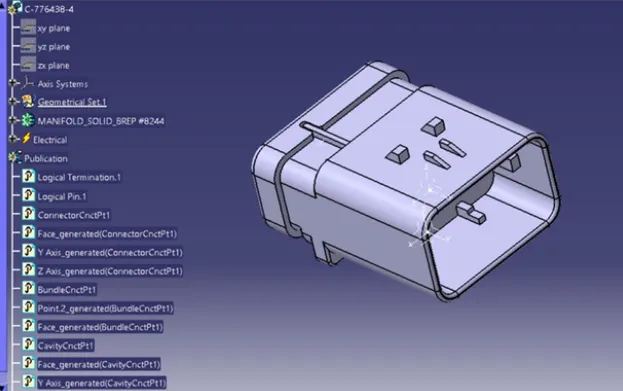
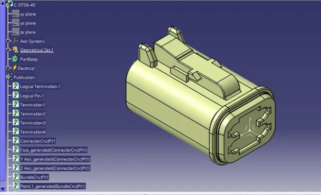
- C-DT06-4S - For taillight (4 pole connector).
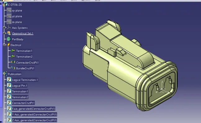
- C-DT06-2S - For number plate light and for viper sensor (2 pole connector)
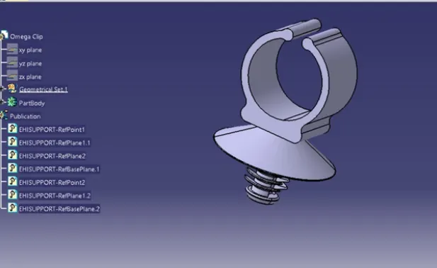
- OMEGA CLIP
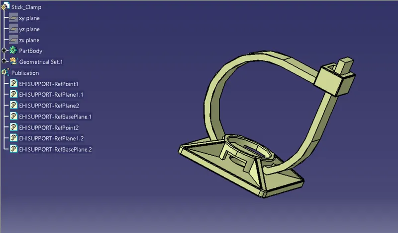
- STICKY CLAMP
STEP 3 - Mounting the Clips and Place the Connectors
- All the arrow marking symbol shows the position of all the clips and clamps according to the requirements.
- Here we used 8 sticky clamps and 12 omega clips.
- We used a variety of commands, including manipulation, snap, smart move, compass, and so on, to place the Omega clips and Connectors.
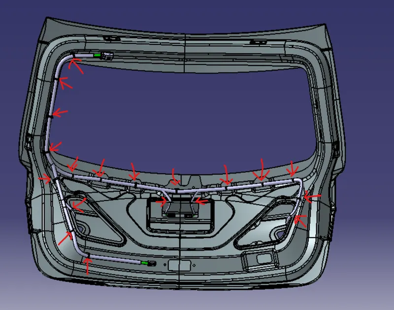
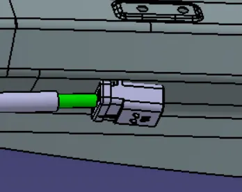
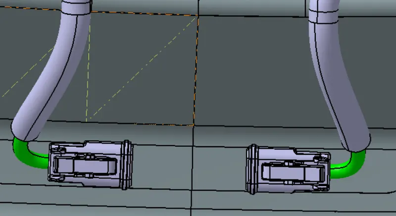
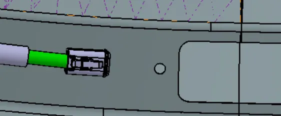
- All the connectors are placed according to their requirements.
- 5 connectors are used and 1 inline connector is used.
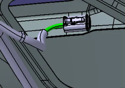
STEP 4 - Bundle Routing:
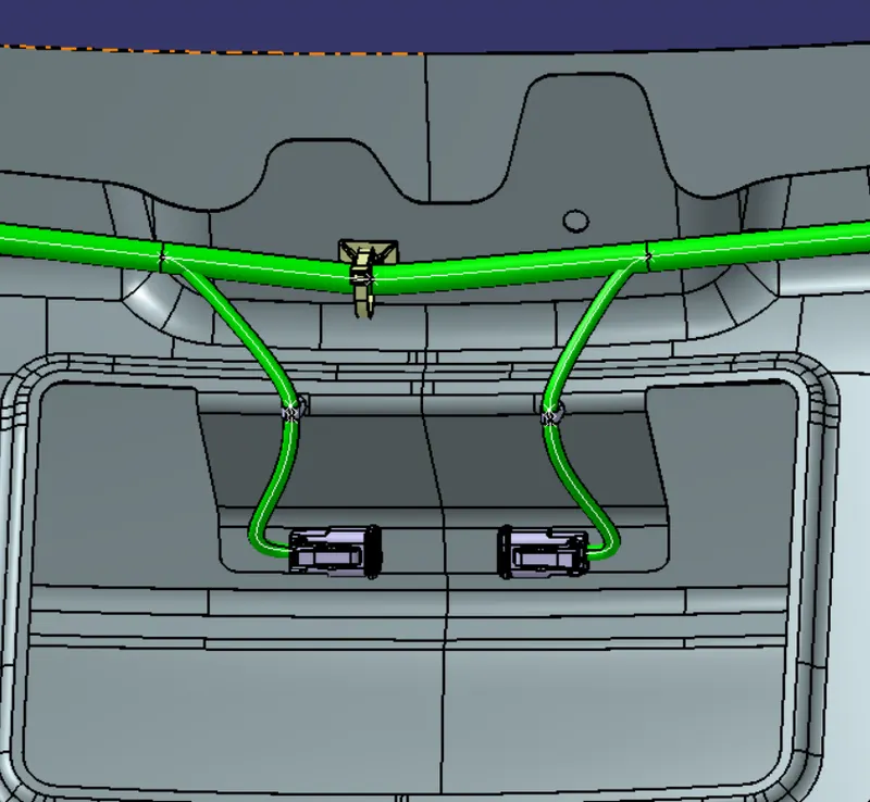
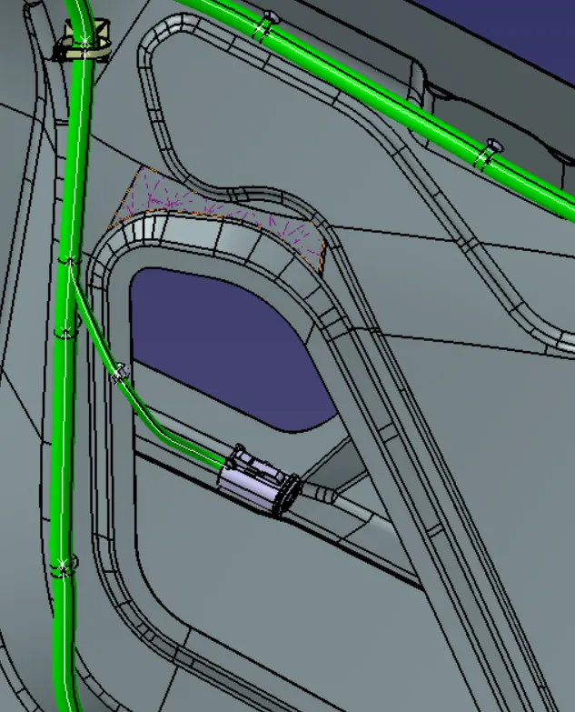
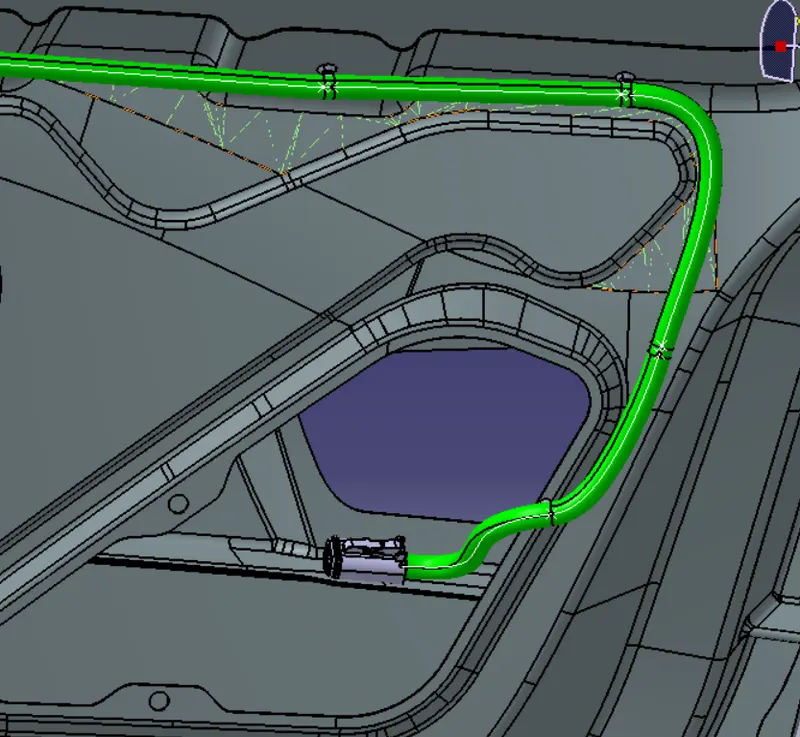
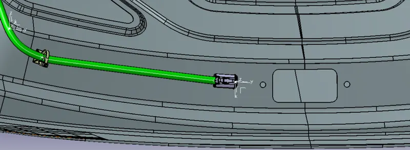
- The bundle segment is steered toward the 4 and 2 Pin connections using sticky clamps and omega clips, maintaining a bend radius ratio of 1.4 throughout the routing process.
- Here the bundle diameter we use 10mm and 5mm.
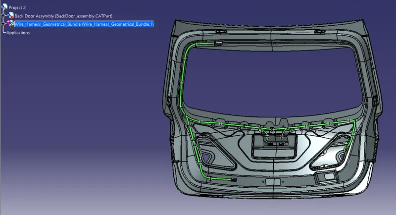
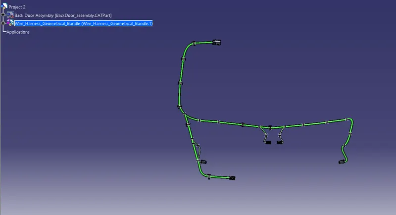
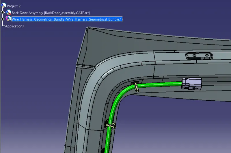
STEP 5 - Adding protective coverings
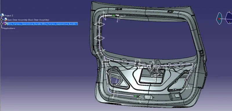
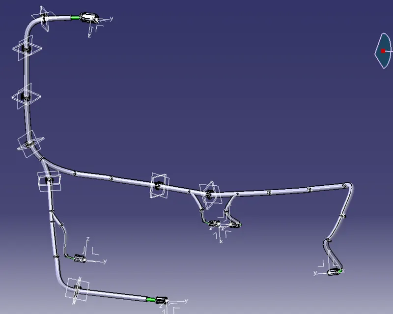
The whole wiring harness layout for the Backdoor is shown in the image below. Now, all bundle segments must be covered with protective coverings.
STEP 6 - BUNDLE SEGMENT CHECK
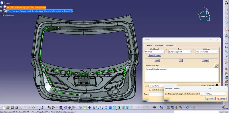
Before moving on to Edit>Search>Advanced>Workbench-Electrical>Type-Bundle Segment>Attribute-Fully Connected in this step, we must first make sure that multi-branch capability is selected.
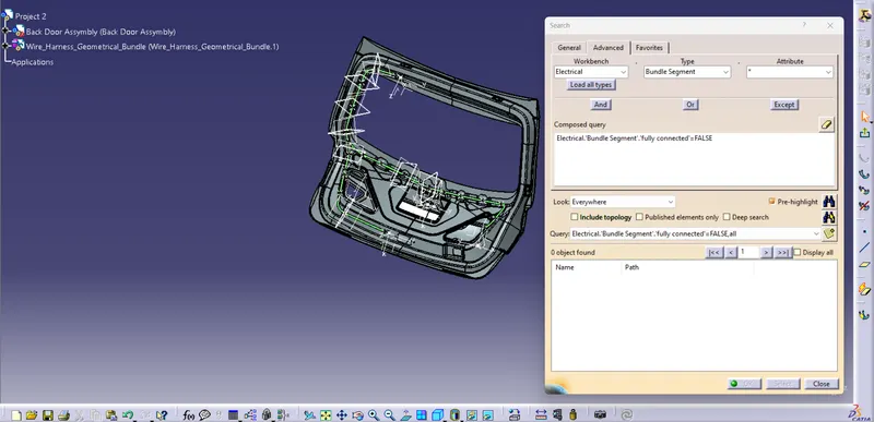
All connected bundle segments are displayed when "True" is chosen, whereas all disconnected bundle segments are displayed when "False" is chosen.
In this instance, we selected the 'FLASE' option and ran a search. As there is an error in the bundle segment so its shows nothing.
STEP 7 - HARNESS FLATTENING
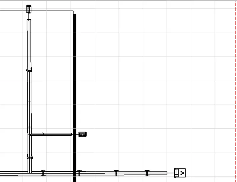
To produce a flattened view in this stage, we'll use the Electrical Harness Flattening workbench in Catia V5. The flattening file should be saved in the same folder as the other harness assembly files, as well.
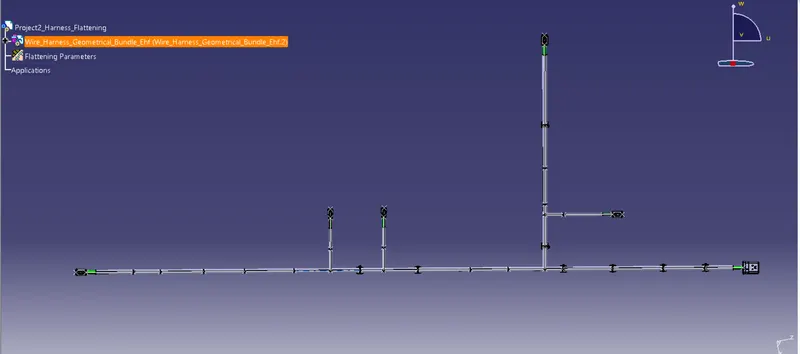
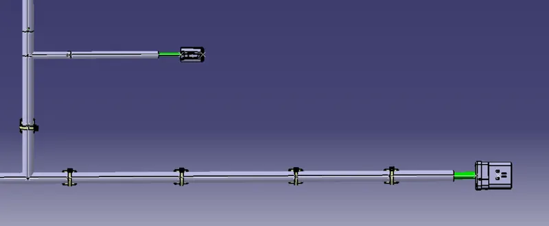
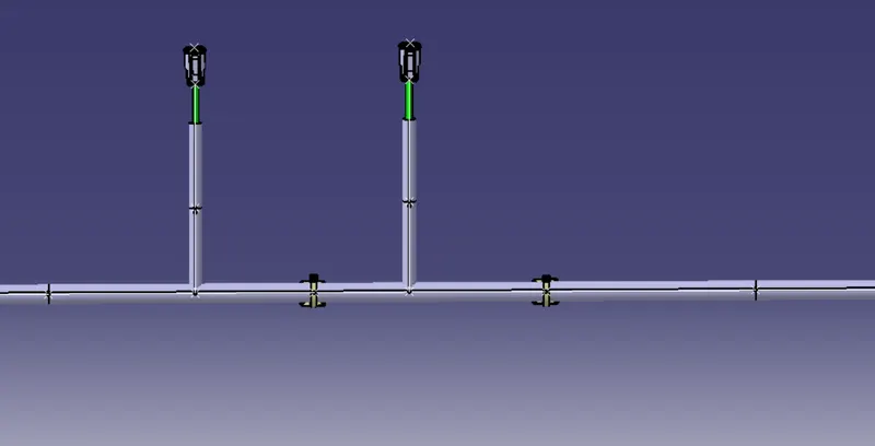
STEP 8 - DRAFTING
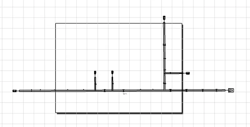
Creating a new drawing file and specifying all necessary drawing settings are shown in the above figure. The Drawing file needs to have the front view of the Backdoor wire Harness Flattening product file. We need to define drawing properties, as seen in the preceding figure. It should be noted that in the "Dress up settings," the 3D wireframe is always ON. The bundle segments won't be seen in the drawing view if this option is disabled. Final Drawing view: Backdoor wire harness flattens.
Conclusion:
So, after creating a drawing and routing the bundle assembly with protective covering, the drawing is now prepared for pre-release