Project 2
PROJECT :2 BACKDOOR
AIM:
Route the Wiring harness on Given car body and Prepare flatten view drawing in CATIA V5. Application of all Packaging rules, Industry best practices studied in this course shall be demonstrated in design. Apply Protection coverings to all bundle.
GIVEN BACKDOOR MODEL:
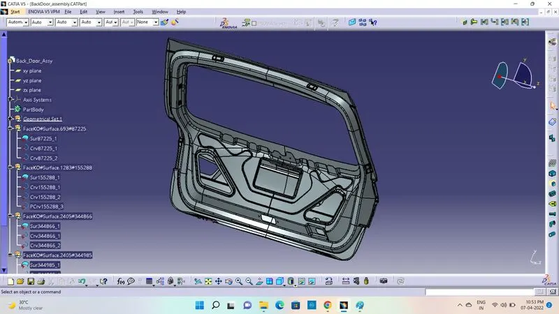
PROCEDURE & ASSUMPTIONS:
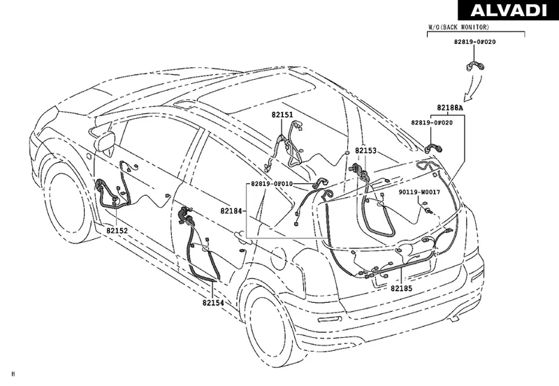
- Provide clips/clamps as per requirement.
- Make sure that there is no any fauling case while designing the wire harness. Additional clips/clamps may be used to avoid fauling case.
- Give additional slack if needed. 5-15% slack is sufficient.
- Avoid routing on sharp edges or else provide protection over the harness.
- Follow the clearance distance and keep away the harness from heat generation components.
- Protection should be provided as needed according to surrounding temperature.
- Branch length should be greater than 50mm.
- Minimum distance between two branch points should be at least 50mm.
- Minimum distance between clip and branch point should be at least 25mm.
- Avoid too many sheet metal brackets on the engine.
- The wiring harness should be easy to assemble and easy to access.
- While using dummy connectors, ensure that whatever positions you are defining that are practical. Bundle diameters and another placements can be defined properly for the wire harness routing.
- If the packaging area is too tight and there are many packaging constraints then we can think of creating harness channel which can be used to route and protect the wire harness effectively.
STEP:1
CONNECTOR:
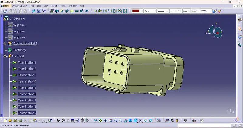
C-776438-4d-3d:
- Download all Connectors from Website and Defined ElectricallyAby Geometrical Sets.
- Points and Axis Sytems are used to defining the Connectors.
- we should define it as a electrical device and it also defined as the 12 pole connector.
- It as to be defined as the connector connectoin point and a bundle connection point.
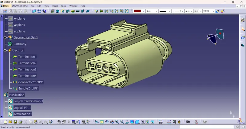
C-1563684-1-b-3d:
- As we mentioned for the previous connector as well as the same Points and Axis Sytems are used to defining the Connectors.
- we should define it as a electrical device and it also defined as the four-way connector.
- It as to be defined as the connector connectoin point and a bundle connection point.
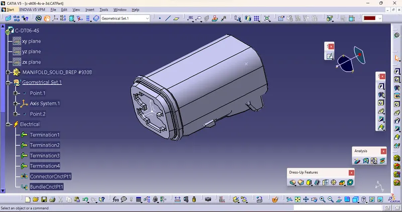
C-DT06-4S-a-3d:
- It defined as the four-way connector.
- It as to be defined as the connector connectoin point and a bundle connection point.
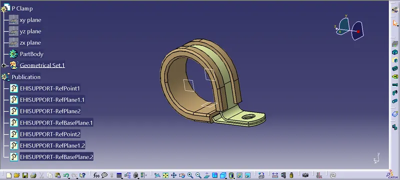
STICK CLAMP:
- The wire clamp stick is used to hold tie wires in place, hold jumper wires while taps are being made or removed, and to hold wires when cutting and removing.
- It is safer to avoid the wire lossening in the car door and also it holds the wire bundle in prooper direction.
STEP:2
ASSEMBLY PROCESS:
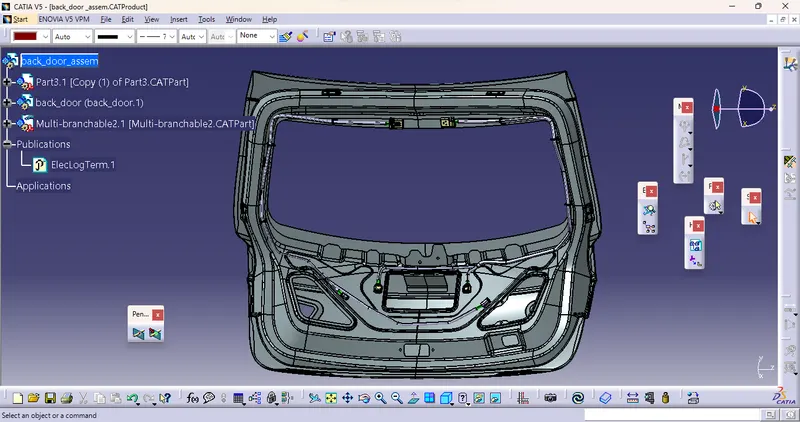
- First of all, the connector should be placed over the backdoor with the help of assembly design workbench.
- Place the connector one by one on the backdoor with the help of the manipulation toolbar and the compass.
- Arrange it all together and placed it in all proper manner to route the wiring bundle through the direction of the connectors.
- From the electrical harness workbench,we need to select the geometeric bundle option and move on to the mltiple-bundle segment.
- Now, remember one thing we have route the two multiple-bundle segments.
- Then, route the bundle by the route definition and add the 'Add branch point' to avoid the same bundle errror.
STEP:3
ROUTING PROCESS:
- First Defining all the connectors as electrical components and the clips as the supporting equipment.
- Locate all the connector , clip, and cavity at the desired location.
- Now by using multi-branch bundle route all the connector with the clip and clamp
- By create a catlouge and add the protection cover od 15mm diameter and 8 mm diameter.
- Now by using protection covering tool , protect all the bundle.
- Create a gap from the end and start extremity by 10mm or 20mm.
STEP:4
CHECK THE BUNDLE CONNECTIVITY
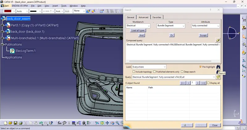
- To check the bundle connectivity error press 'ctrl+f'.
- Then, we have select the advance and 'electrical', 'bundle segment', 'fully connected'.
- click to the false then 'search' it will show nothing. obiviously it is fully connected.
- This how to check continutiy of bundle segments of assembly and after doing all process give all bundle to pvc protection covering and move further to make new produts as flattening of given following bundle of harness and make sure hareness parameters will define correctly.
STEP:5
ELECTRICAL HARNESS FLATTENING
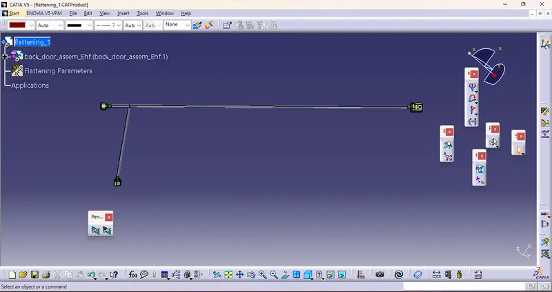
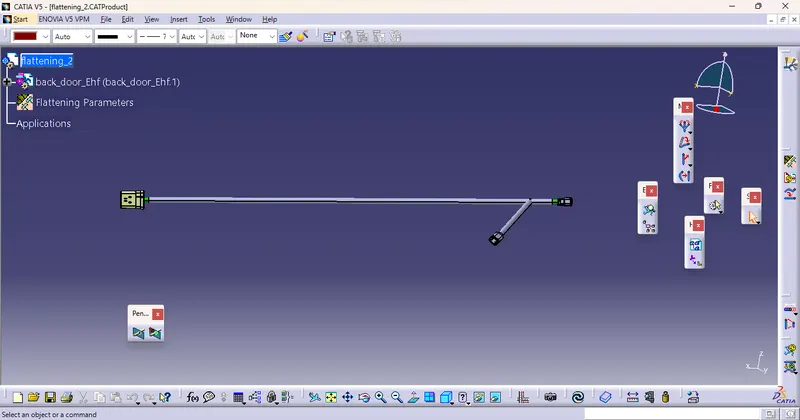
- So, we have the two multiple-bundle segments to used for the harness flattening.
- Before that we have to enable the 'harness flattening parameters' in the electrical harness flattening workbench.
FLATTENING:1
FLATTENING:2
STEP:6
DRAWING SHEET