Project 2
Route the Wiring harness on the Given car body and Prepare to flatten view drawing in CATIA V5. Application of all Packaging rules, Industry best practices studied in this course shall be demonstrated in design. Apply Protection coverings as required.
Available connector 3D data can be used, or you can download the connectors from www.te.com
Prepare & Submit all necessary reports like clearance, Clipping/Clamping selection, Harness fixing requirements, Harness continuity, and Assumptions if any along with CATIA 3D data.
DACK DOOR WIRING HARNESS ASSEMBLY
AIM
Route the Wiring harness on given Car Hatch and prepare a flatten view drawing in CATIA V5.
Objective:
The objective of this project is to route the wiring harness and prepare to flatten view drawing for the tailgate of the car. All types of packaging rules have to be considered while routing the harness and industry based practices shall be demonstrated in harness design. All necessary details like clearance, clipping/clamping selection, harness fixing requirements, and harness continuity should be provided in order to design the wiring harness.
Introduction
The back door of the car is also known as Tailgate. This is a critical part of back impacts that occur in accidents, which should ensure that crashes wouldn’t injure the passengers. The back door consists of one inner panel and two outer panels. Most of the time the back doors are made from steel or aluminium or plastic based on the budget and the weight of the car the material is selected. In the case of the aluminium, the strength of the back door would be stronger, therefore, reinforcement is not required indeed which will reduce the overall weight of the part. But aluminium is a bit more expensive than steel.
THE BACK DOOR IMAGE IS SHOWN WITH REINFORCEMENT

BACKGROUND, TECHNICAL SPECIFICATIONS, AND ASSUMPTIONS-
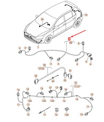
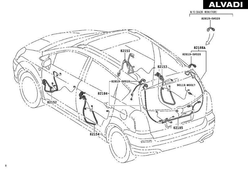
Below are a few references from the real world which were considered while designing the wiring harness for this project
1.Easy manufacturing, installation, removal, and maintenance have to be considered while designing the wiring harness.
2. Routing through small structural holes or openings shall be avoided to minimize chaffing and handling during installation.
3. Avoid harness routing and clipping in the blind zone or hard-to-reach areas during harness assembly or in service.
4. Provide additional slack if needed according to the surrounding and harness bending requirement. For this project, a slack value between 1-5% is used.
5. It should be made sure that there is no case of fouling while designing the wiring harness in the CAD environment. Additional clips/ clamps may be used to avoid fouling.
6. Avoid harness routing near sharp edges or else provide protection over the harness.
7. Enough mounting equipment such as clips and clamps should be provided.
8. The branch length should be greater than 50mm.
9. The minimum distance between the clip to the branch point should be at least 25mm.
10. The minimum distance between the two branch points should be at least 50mm.
11. The wiring harness should be easy to assemble and easy to excess.
12. Clips/ clamps used for the wiring harness should be easily available in the market to avoid extra cost for custom mounting solutions.
The back door image is shown below
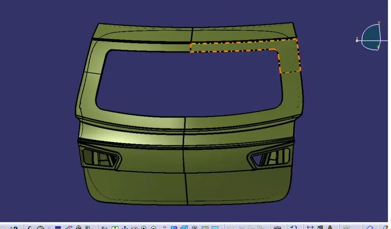
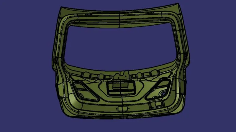
- We have created context assembly for the tail gate of the car as main assembly as shown in above figure.
- This context assembly contains the 3D cad data for the tail gate of the car and car tail gate harness geometrical bundle.
THE CONNECTOR AND CLAMP ARE SHOWN BELOW
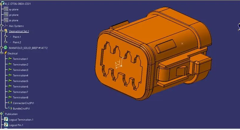
- Here, we will use 3-Pole and 8-Pole connectors for this assembly and for that we have downloaded these connectors from TE.Com
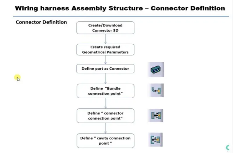
- We should have to define it electrically that is to define geometrical parameters, bundle connection point and connector connection point.
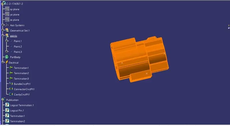
THREE POLE CONNECTOR
CODE : C-2-174357-2
EIGHT POLE CONNECTOR
CODE : C-DT06-08SA-CE01
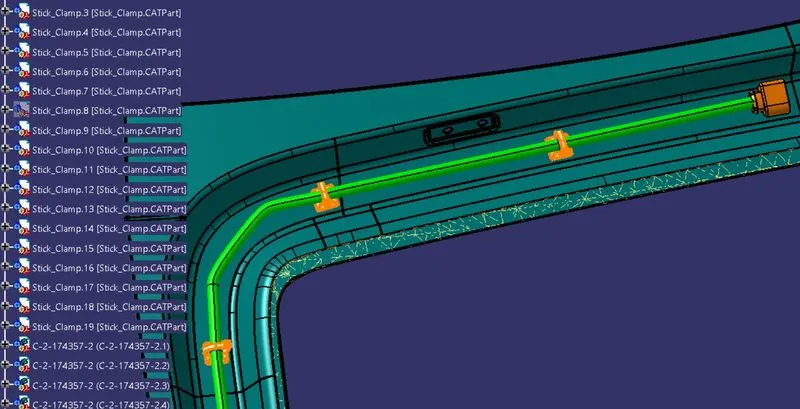
IN THIS MODEL WE ARE NOT USING HOLE INSERT OF MAKING HOLES WE USING STICKY CLAMPS TO AVOID HOLES FEW STICKY CLAMP IS USED TO PROTECT YOUR WIRE IN PLACE.
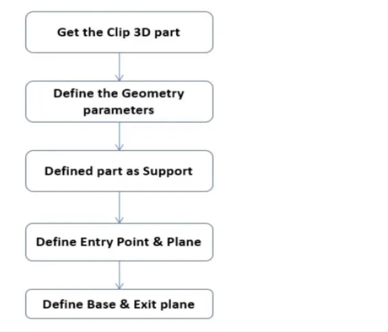
- The given clip was downloaded and opened in CATIA as a part file.
- And define two points that will be used as entry and exit points.
- after that, a plane has to be created at the points.
- A base plane has to be defined at a distance of 2 to 3 mm from the clip.
- again we define the exit point in the first definition as the entry point.
- finally, we got two entry and two exit points.

All the 3-pole connectors are added inside the Body harness geometrical bundle assembly. Manipulation tools along with a compass, snap, and smart move features should be used to locate all 4 connectors in their desired locations. These connectors are shown in orange colour for clarity.
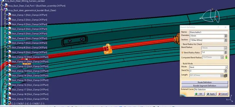
BUNDEL PARAMTERS IS SHOWN FOR TOP BUNDEL
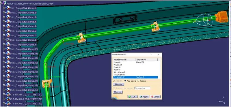
Locating and placing clips in the desired locations is shown below
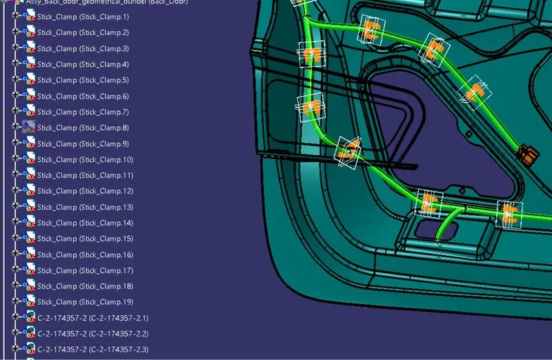
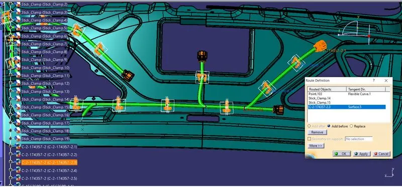
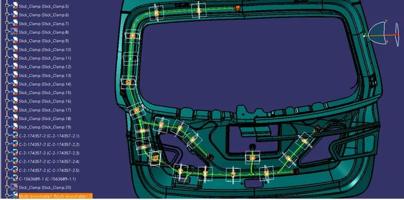
- Let, we have started bundle routing from the interconnection connector and the assumed diameter of the main trunk is 10mm.
- The diameter of the bundle leading to 2 tail lights and 2 number plate lights is 1omm and 5mm respectively.
- The bend ratio is assumed to be 1.4 to 1.5 and appropriate slack between 1-10% is given wherever needed.
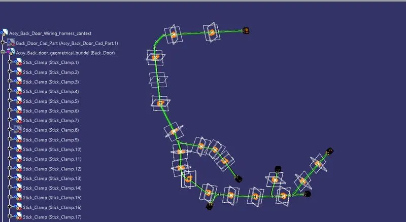
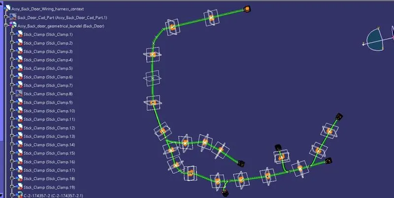
bundle with back door cad part
Protective Covering
Adding a protective covering to the harness bundle is important to keep the bundle together and protect it from any wear and tear. For the current harness assembly, we will be using a brown-colour PVC tape. Start and end extremity should be given wherever needed for the PVC tape.
Checking Bundle Continuity
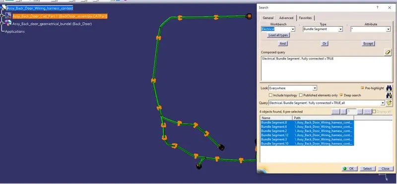
Selecting the 'True' option will show all the connected bundle segments while selecting the 'False' option will show all the non-connected bundle segments. Here, we have selected the 'True' option and searched for results. All the bundle segments are highlighted found showing that all the bundle segments are electrically connected as shown in the below figure.
The 'False' option will show all the non-connected bundle segments.
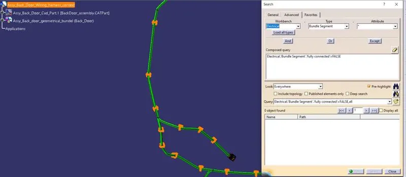
in the step, for creating flattened view we have to work in the Electrical Harness Flattening workbench of Catia V5. We should also make sure that the flattening file is saved in the same folder where other files of harness assembly are saved.
flattening parameters is shown bellow
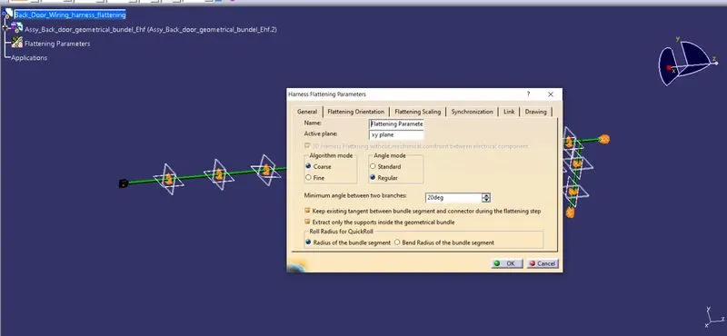
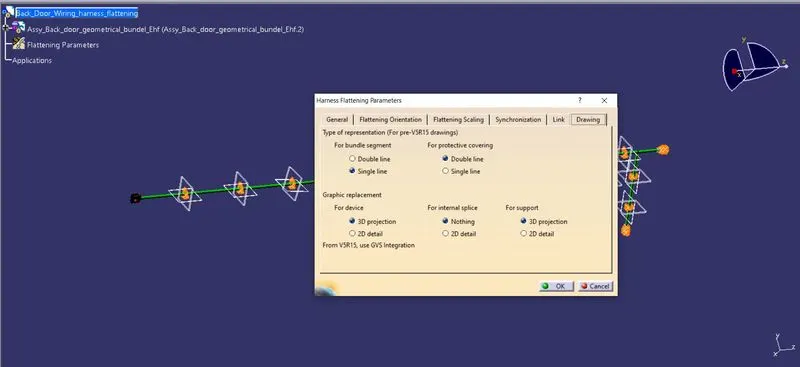
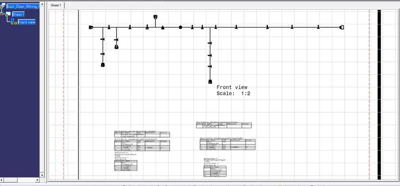
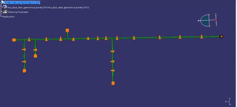
complete flattening is shown below the image.
In the above figure, we are creating a new drawing file and defining all the necessary drawing parameters. We have to insert the front view of the Engine Harness Flattening Product file into the Drawing file.
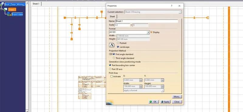
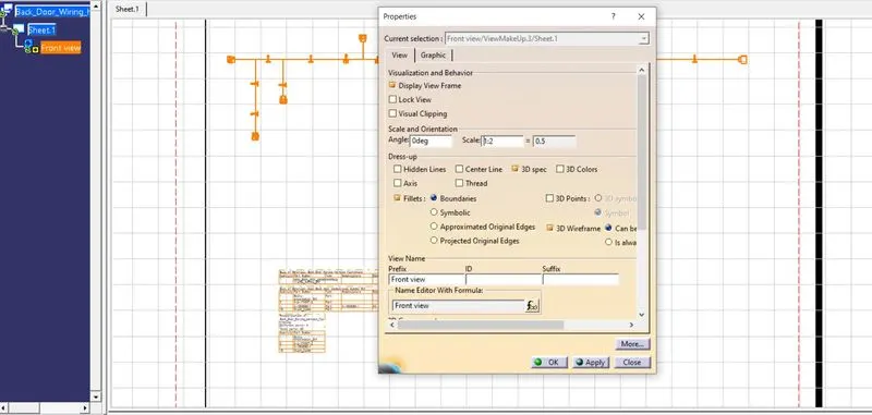
drafting is shown in below
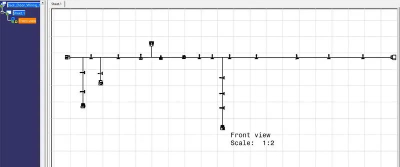
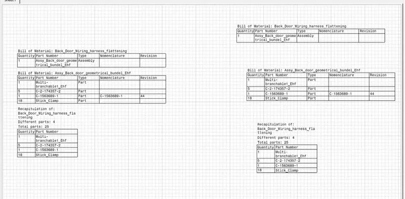
BOM is shown below