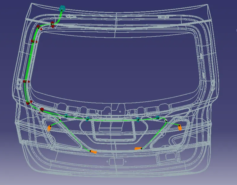
Project 2
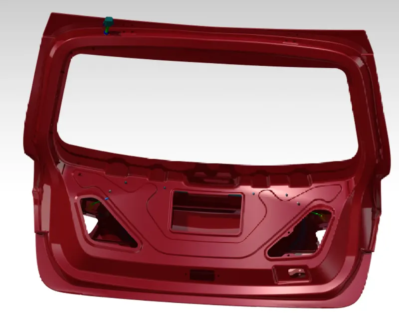
AIM - Route the wiring harness on given car's BACKDOOR and prepare flatten view drawing in CATIA V5.
Objective: The objective of this project is to route the wiring harness and prepare flatten view drawing for the tailgate of the car. All types of packaging rules have to be considered while routing the harness and industry based practices shall be demonstrated in harness design. All necessary details like clearance, clipping/clamping selection, harness fixing requirements, harness continuity should be provided in order to design the wiring harness.
PACKAGING RULES AND ASSUMPTIONS MADE IN THIS PROJECT
- Wiring harness routing shall provide ease in manufacturing, accessibility, easy removal, and easy maintenance of attached equipment and wiring harness.
- Routing through small structural holes and openings shall be avoided, minimize chaffing and handling of the wiring harness during installation.
- Avoid the harness routing and clipping in the Blind zone of the Operator during harness assembly or in service.
- Routing shall offer protection against possible damage through common misuses such as being handhold and temporary support for test equipment.
- Provide additional slack to the harness according to the surroundings and harness bending requirements.
- Ensure the routing meets the clearance requirements with different surrounding parts.
- Avoid routing over the bolts, near to the bolted joints. It may damage the harness or puncture the harness. Keep harness away from panel mounting screws.
- Avoid harness routing near sharp edges, if not possible provide protection to the harness.
- The maximum distance between two clips on a straight branch is 200mm.
- Provide Clips and clamps if the harness is going to bend at multiple locations.
- The use of too many sheet-metal brackets should be avoided.
- The branch length should be more than 50 mm.
- Min distance between clip and branching point to be 25 mm.
- Min distance between two branch breakouts should be 50 mm.
Download car body model on which wiring harness to be routed :-
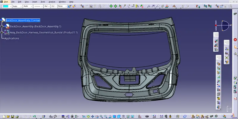
Backdoor modal is download as an igs file .which is saved as a CAT PROJRCT , for easy hendeling of larger assenbaly this CAT .
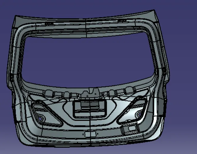
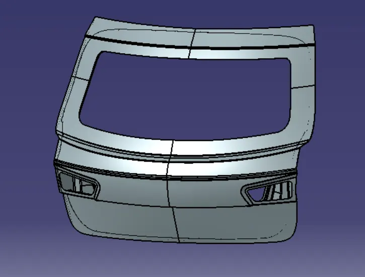
Creating Backdoor assembaly context:-
Define the Connectors :-
Here, according to the requirement, we are using
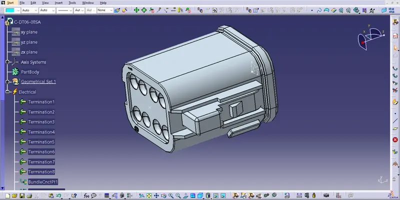
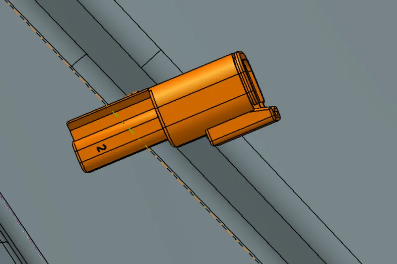
- 'C-DT06-08SA' Which is a 8 Pole connector is used as an inline Connector
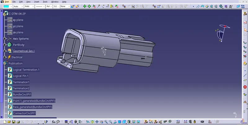
- 'C-DTM-04-2P' which is a 2-pole connector for Taillight and Number Plate Light
This CAD data was obtained from te.com. To electrically define a connector, we must first define the geometrical parameters such as the bundle connection point and connector connection point in the Electrical Part Design workbench for the downloaded connector.
'C-DT06-08SA'
In above figure, we have defined 8-Pole connector electrically for two tail lights of the car.
'C-DTM-04-2P'
Here, we have defined 2-Pole connector electrically for two number plate lights of the car as shown in above figure.
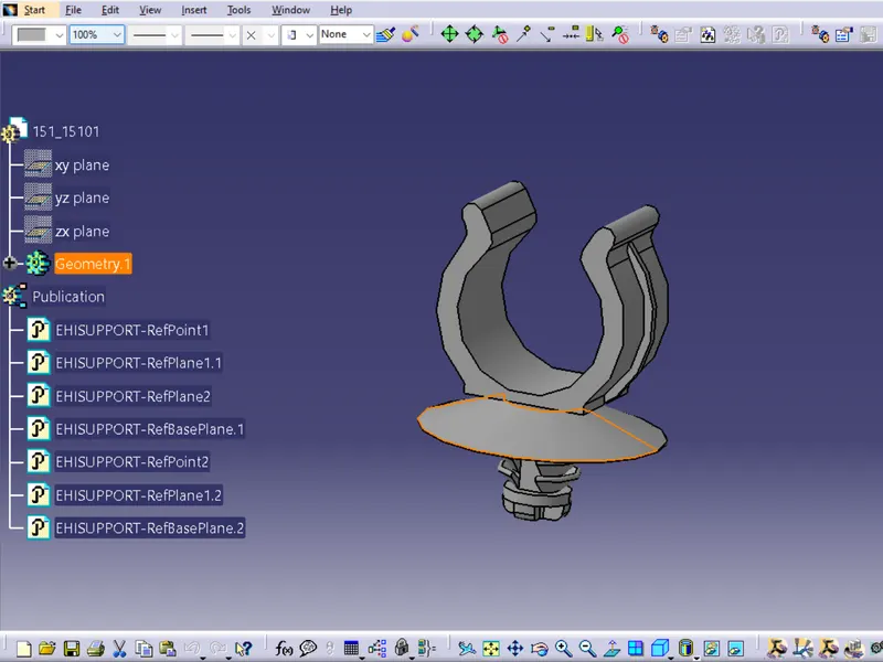
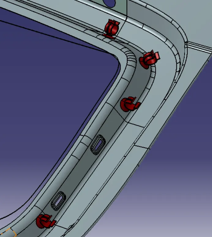
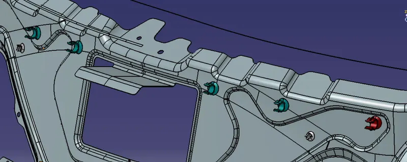
For Support, we use Omega Clips
We need to mount the Omega clips on the Backdoor to provide support as well as act as a guiding channel, so we must first define it electrically with geometrical parameters, entry, and exit points on both the left and right sides of the clips, as shown in the figure below.
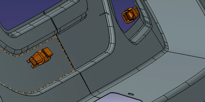
Adding connectors to the 2 tail lights and 2 number plate lights
- We have added both 2-pole connectors and 8-pole connectors inside the tail gate harness geometrical bundle assembly.
- We have used commands like manipulation, compass, snap and smart move to place all the 4 connectors to their desired location.
- We have placed all the connectors at their desired position as shown in below figures.
ounting the Omega Clips and Placing the Connectors
Mounting Points of the Omega Clips
Bundle Segment Branching routing Defination :-
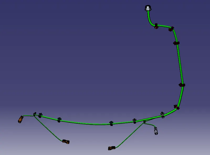
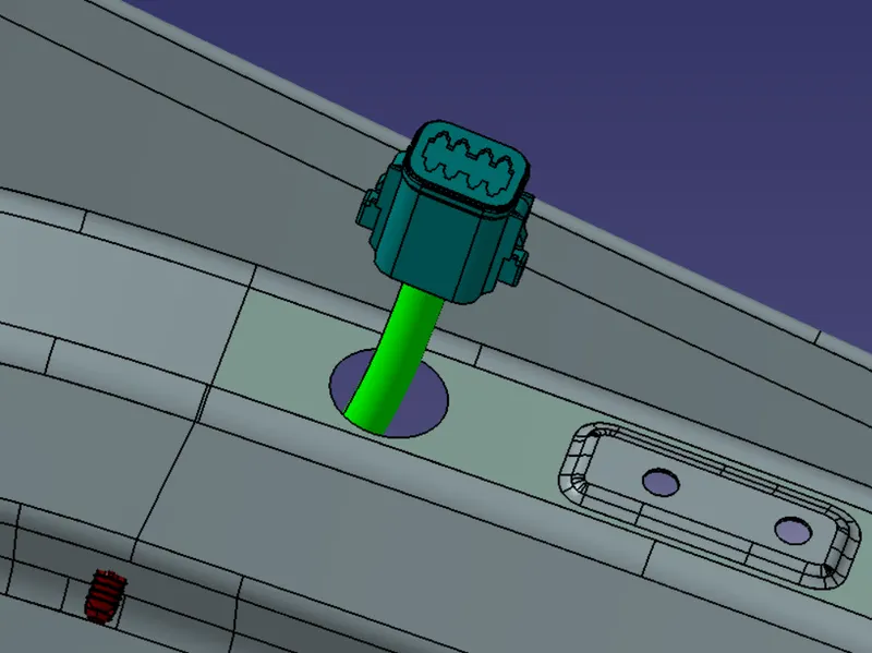
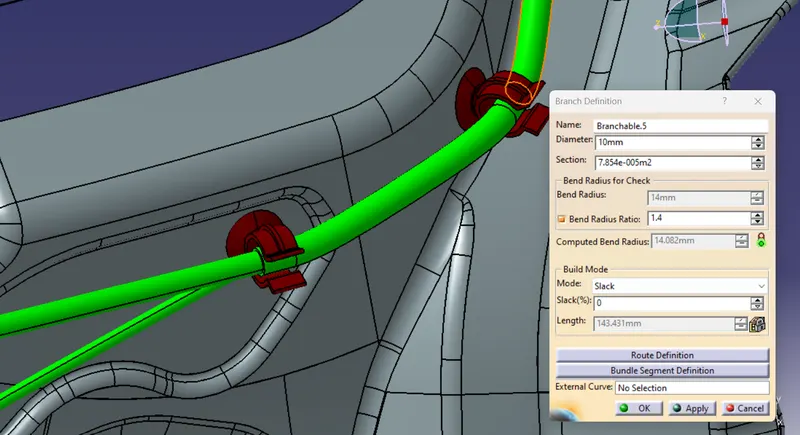
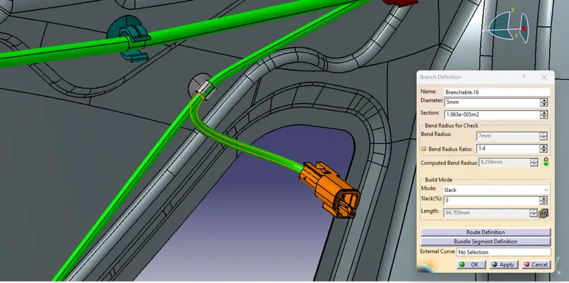
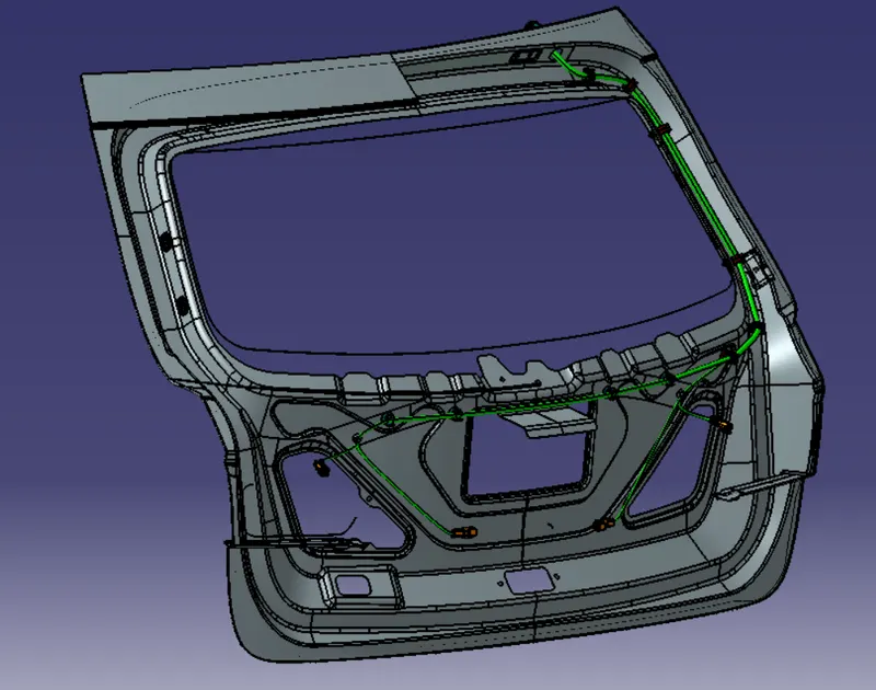
Before, bundle routing we have to make a curve by creating points in hollow part of the given tailgate. So we have made a curve through 11 points from the interconnection connector as shown in below image.
 \
\
Checking bundle continuity
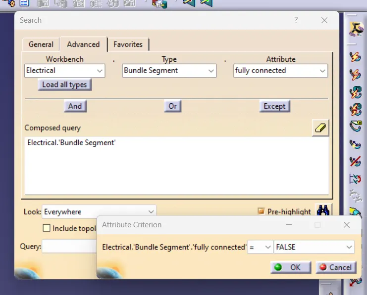
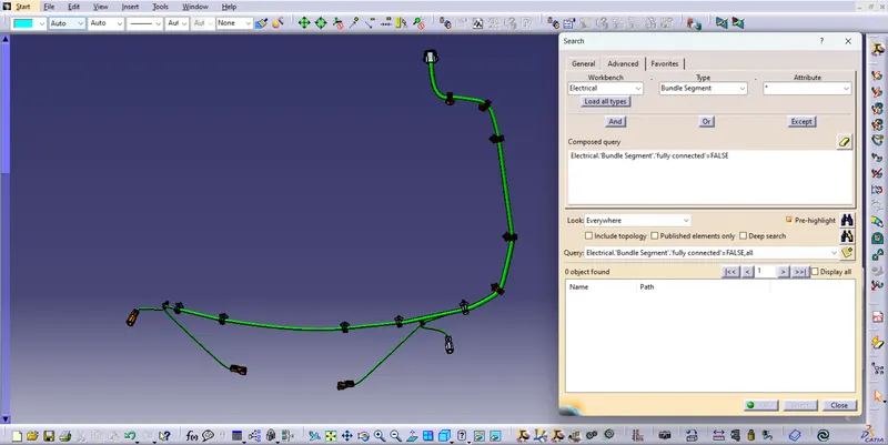
First, we have to select multi-branchable and go through the sequence as Edit>Search>Advanced>Workbench-Electrical>Type-Bundle Segment>Attribute-Fully Connected.After selecting 'FALSE' condition will show all the connected bundle segments while selecting 'False' condition will show all the non-connected bundle segments.Here, we have selected 'True' condition and search for the results. All the bundle segments are highlighted and showing that all the bundle segments are connected electrically as shown in below image.
Create flattening of wiring harness bundle.
To make a flattened view of any wiring harness we should be working in the Electrical Harness Flattening workbench of CATIA V5.We should also make sure that the flattening file is saved in the same folder where we have all the parts of the harness assembly.
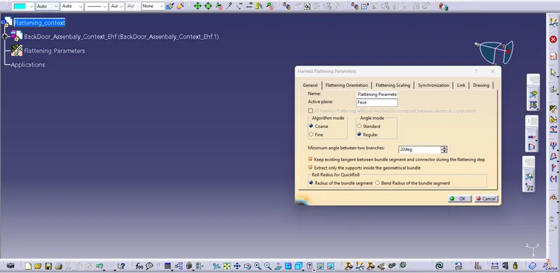
After that, we have to extract and bring the bundle assembly into the car tail gate flattening product file.To flatten the harness assembly, we have selected Face as an active plane and selected all the branches as shown in below image.
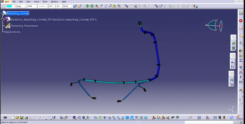
Now, we have a flatten view of the wiring harness geometrical bundle assembly as shown in below image.
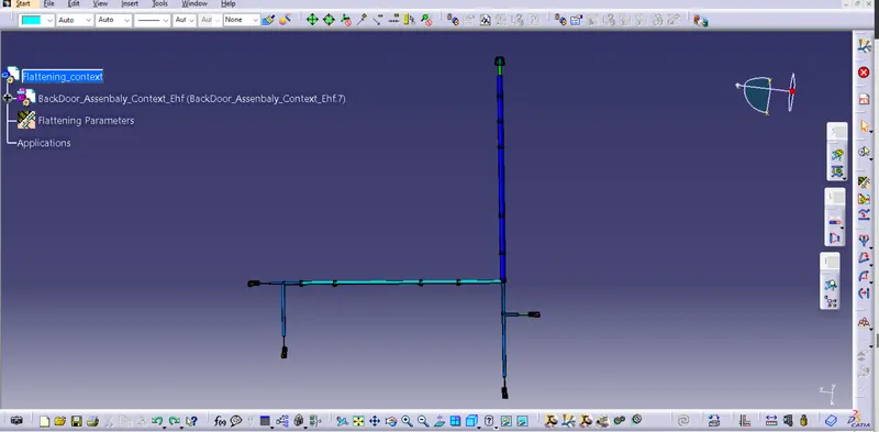
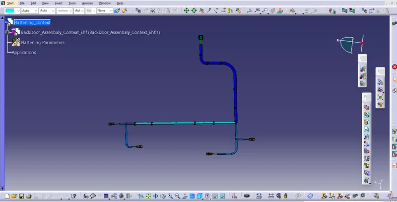
After creating flatten view, we have to rotate the connectors and clips in right direction along the selected plane using manipulation as shown in below image. We have designed the fatten view by using feature like roll for better representation of the harness as shown in below image.
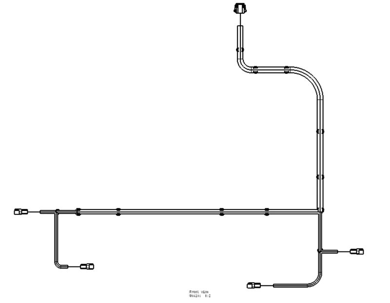
Creating a flatten-drawing view for the wiring harness assembly.
Conclusion:
Routing of the wiring harness for the car tail gate assembly has done and prepared flatten-view drawing in Catia V5. Applied all the packaging rules while routing the wiring harness, implemented industry best practices in the harness design. Also, provided details like clearance, clipping selection, harness fixing requirements, harness continuity in order to design the harness.