Project 2
Aim:
Run simulations, change the threshold, create plots and measure current and hydrogen consumption. Specify the outputs. How to run the model.
Simulation Model:
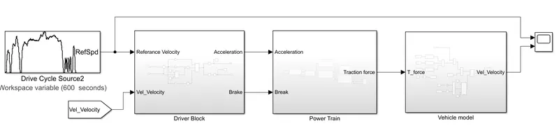
The total model is divided into 3 parts
- Driver block
- Power train block
- Vehicle Model
1) Driver Block:
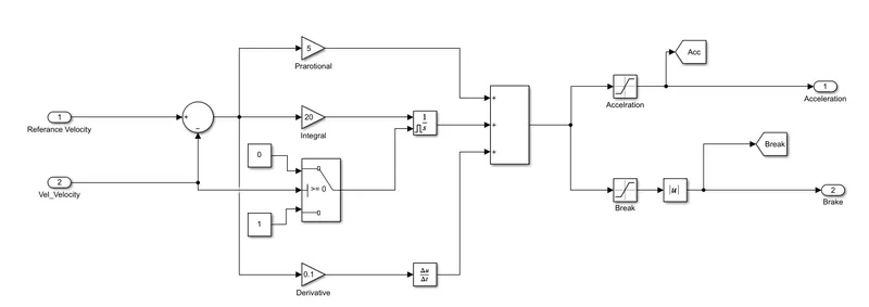
By taking the referance speed and vehicle speed as inputs the Accelerating and Brake command are generated with the help of PID controller as shown above. A switch is used for the Ibtegrator block to avoid the Integral windup when the vehicle velocity is becomes zero.
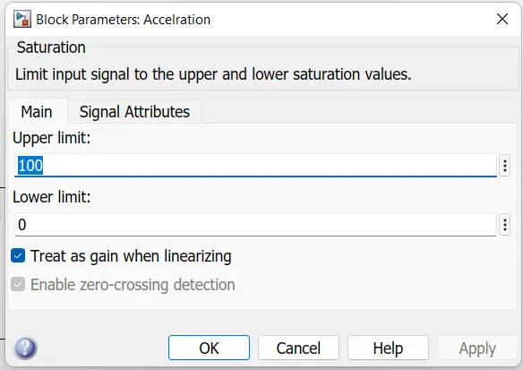
Acceleration saturaion block
Brake Stauraion block
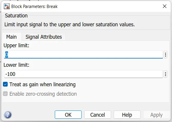
Absloute block is used to eliminate the negitive alue of brake command.
2) Power tran block:
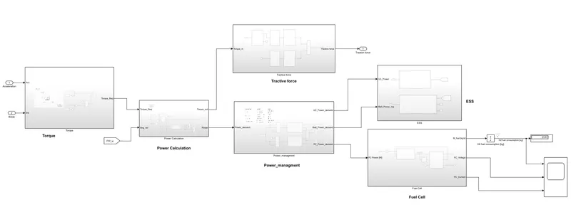
It is a combination of
- Torque calculation
- Power calculation
- Power management System
- Tractive force
- ESS and FC
1) Torque calculation:
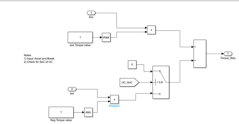
According to the flow chat given below the Torque is calculated
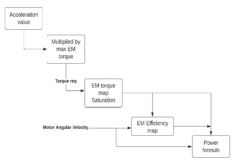
2) Power calculation:
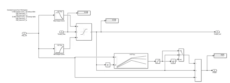
Power is calculated based on the formula
P = torque * angular velocity / Efficiency
Block parameters
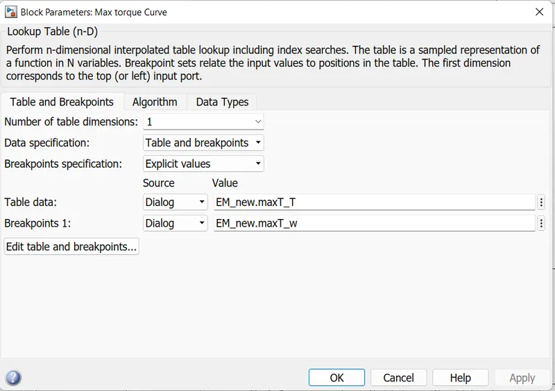
Max torque curve
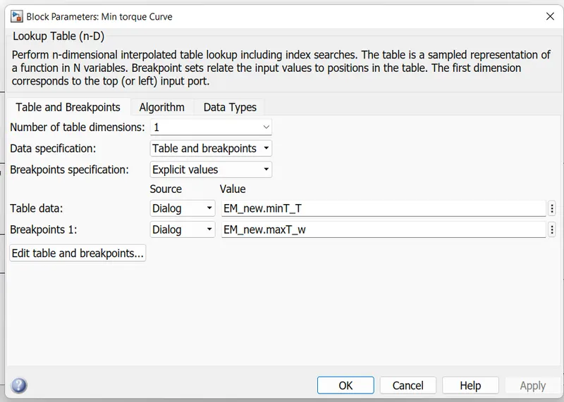
Min Torque curve:
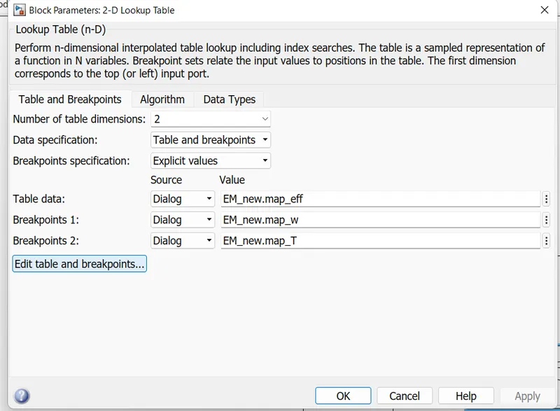
Efficiency,torque, Speed 2-D curve
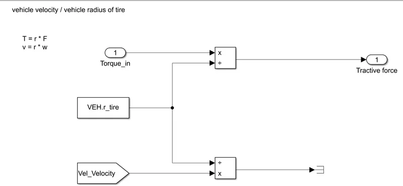
3) Tractive Force;
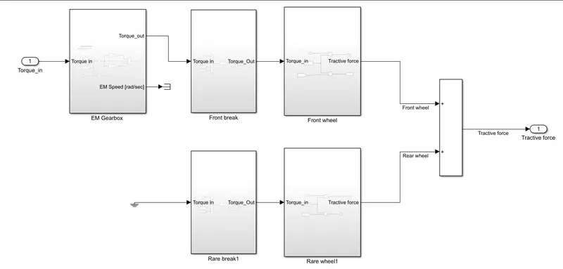
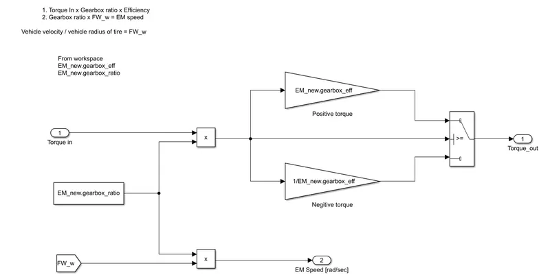
EM gear box:
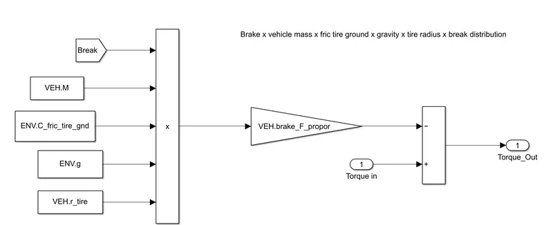
Front brake :
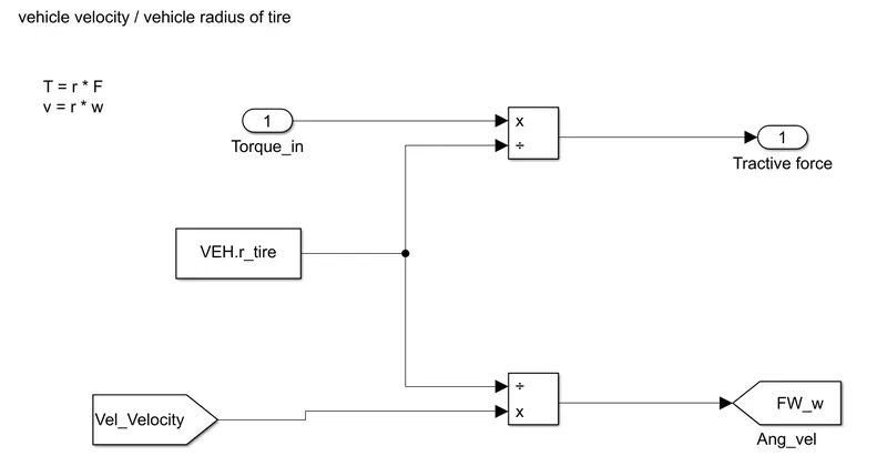
Front wheel:
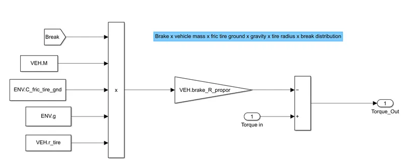
Rear Break
Rear wheel:
3) ESS and FC
ESS
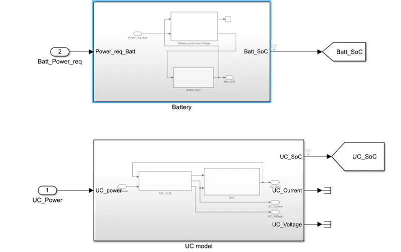
Battery:
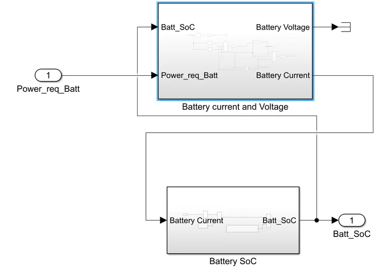
Battery Current and voltage:
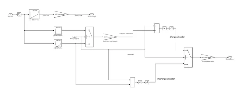
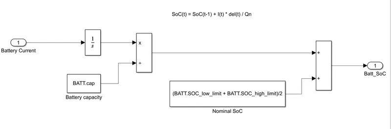
Battery SOC:
UC:
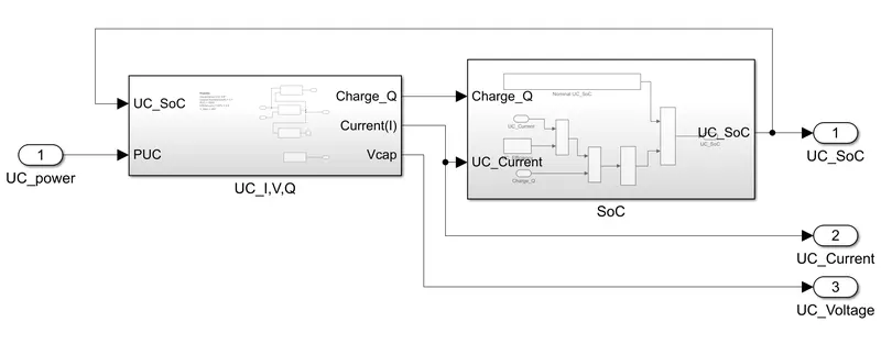
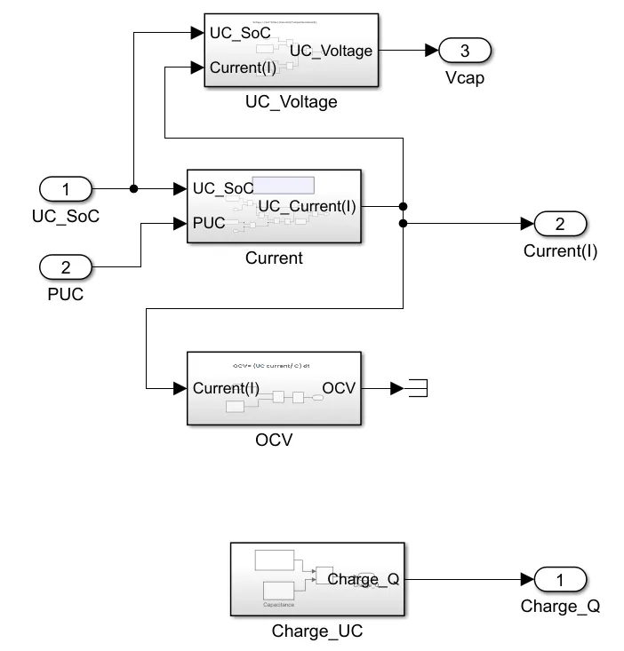
UC_I,V,Q
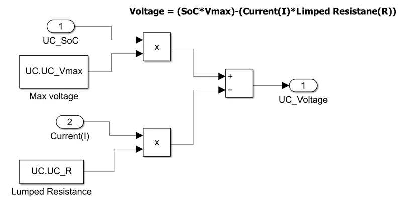
UC voltage:
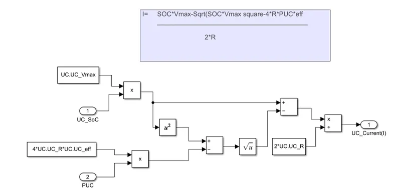
UC current:
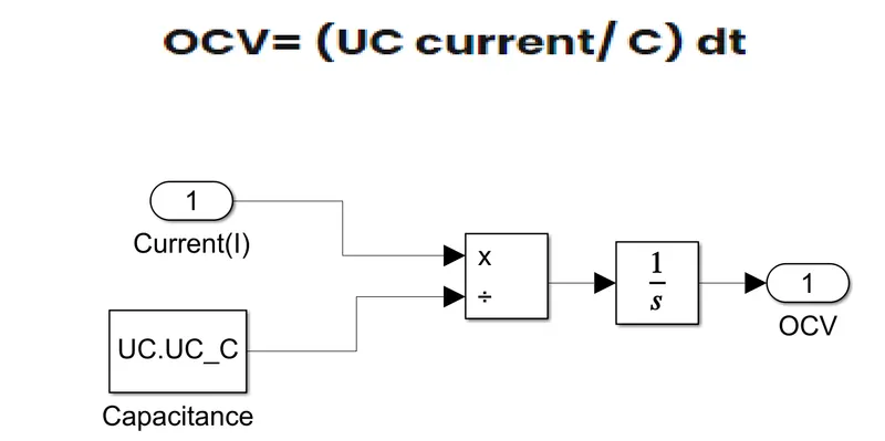
UC OCV
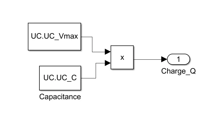
UC Charge:
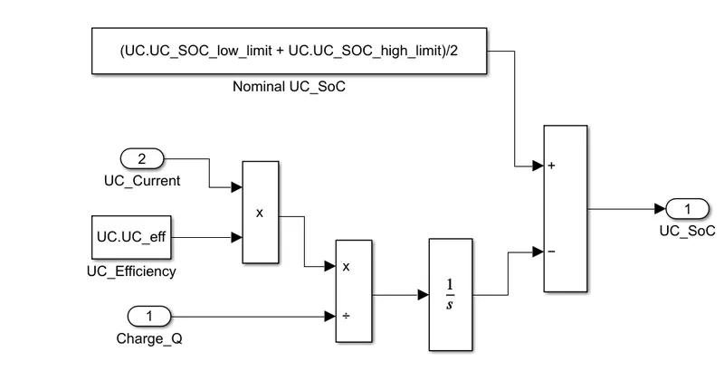
UC SOC:
FC:
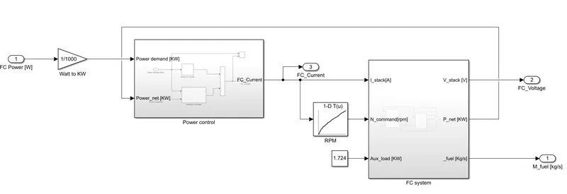
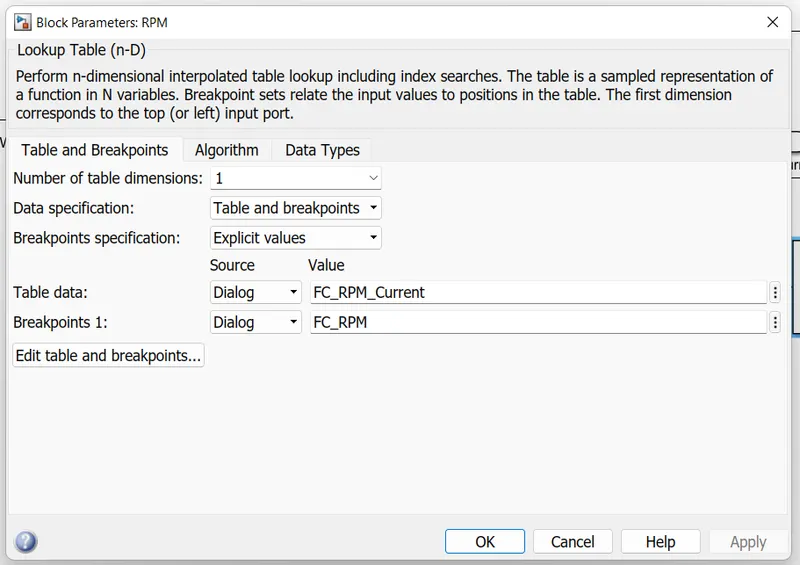
RPM:
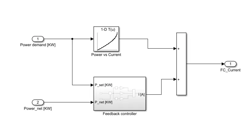
FC power control:
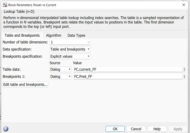
Power Vs Current Block parameters
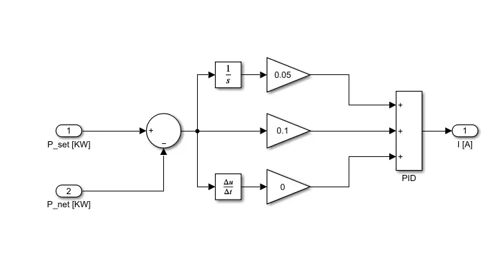
Feedback control:
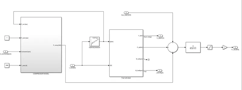
FC System
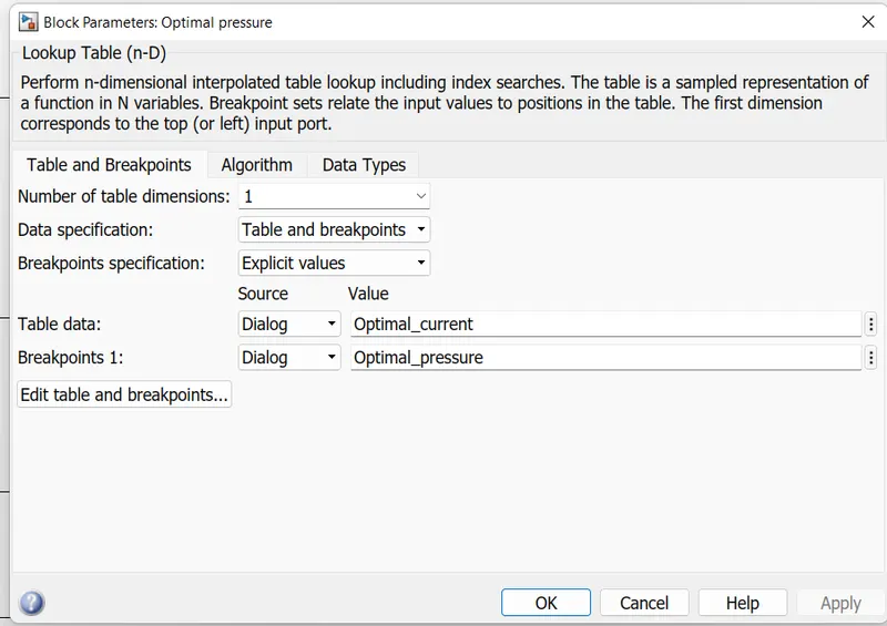
Optimal pressure
Compressor:
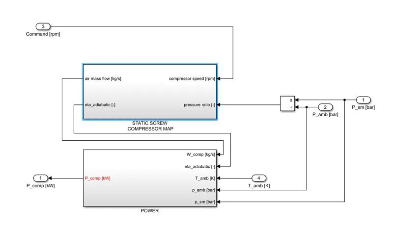
Static screw compressor map:
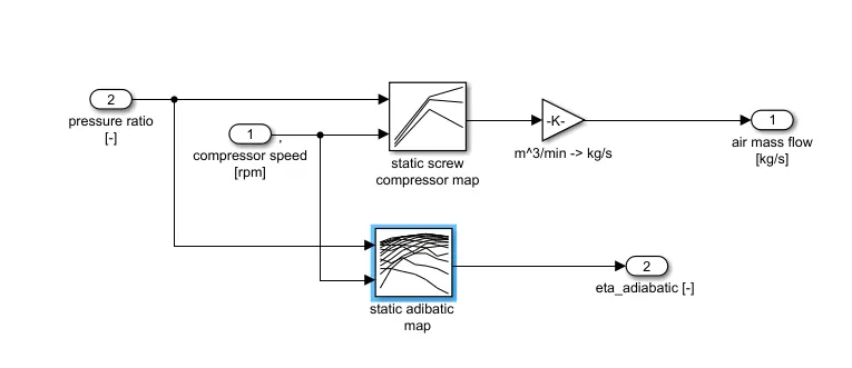
static screw compressor map
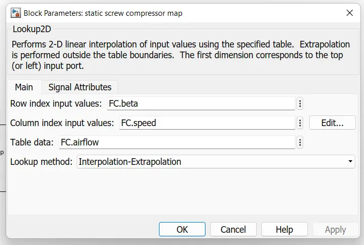
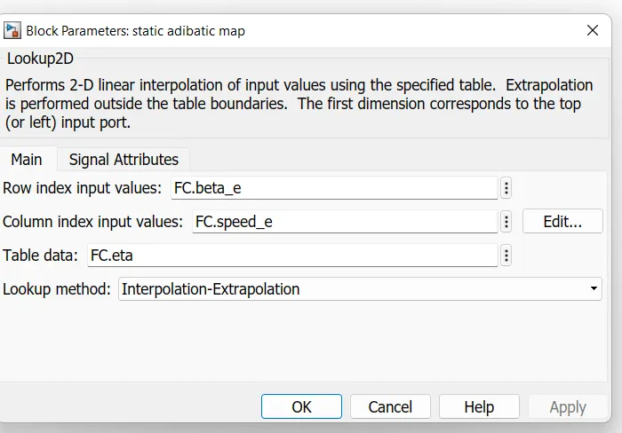
static adibatic map:
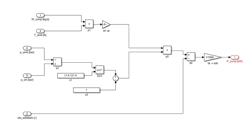
POWER:
FC stack
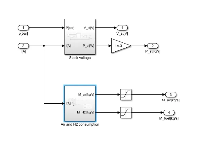
Stack volatge:
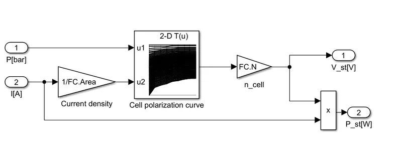
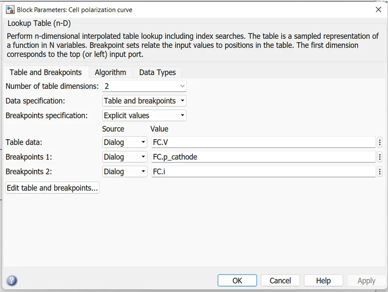
Cell polarization Curve
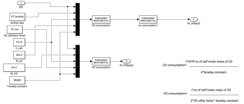
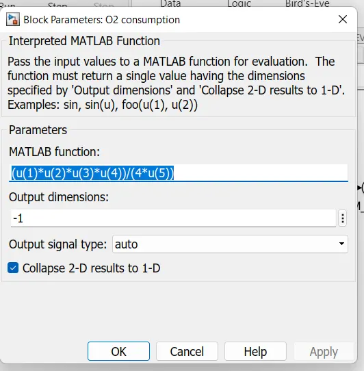
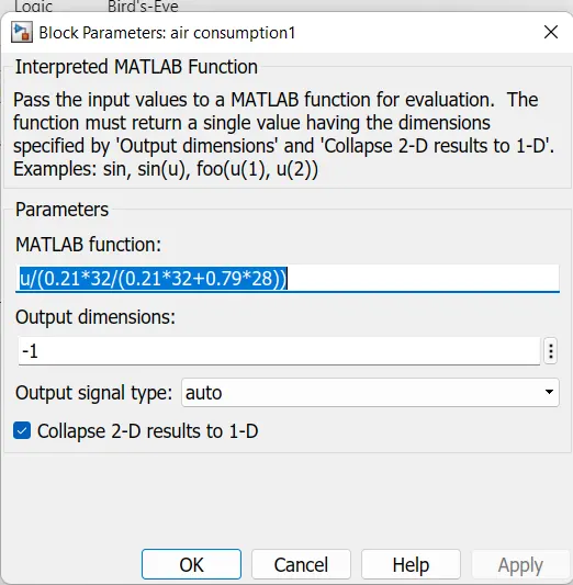
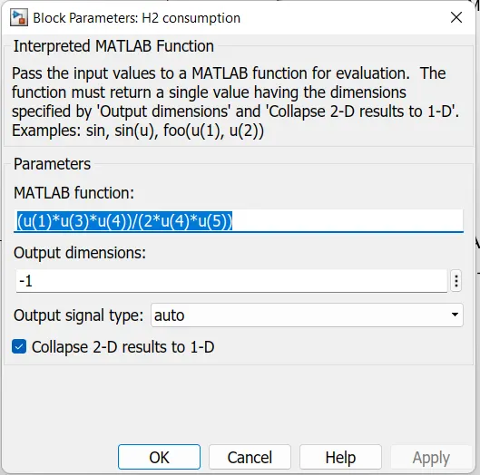
Air and H2 consumption
3) Vehicle Body
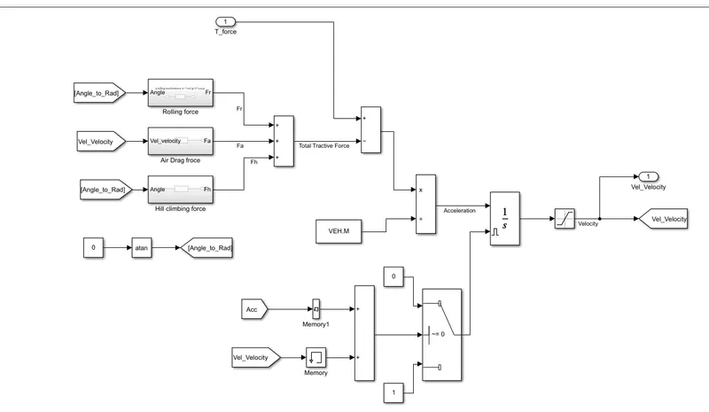
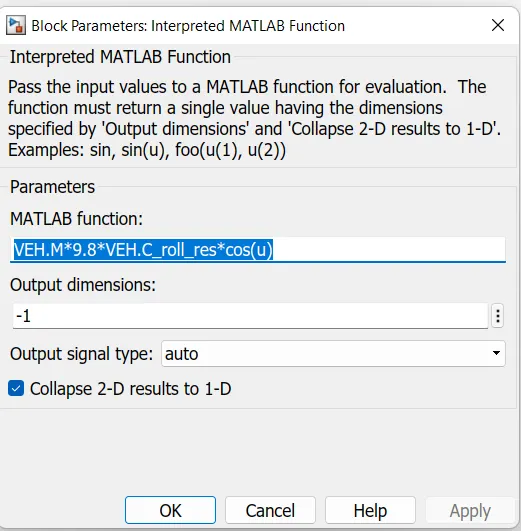
Rolling resistance:

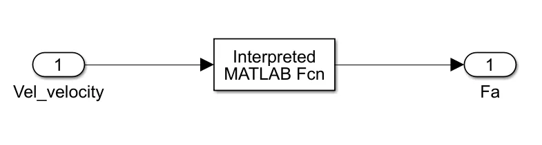
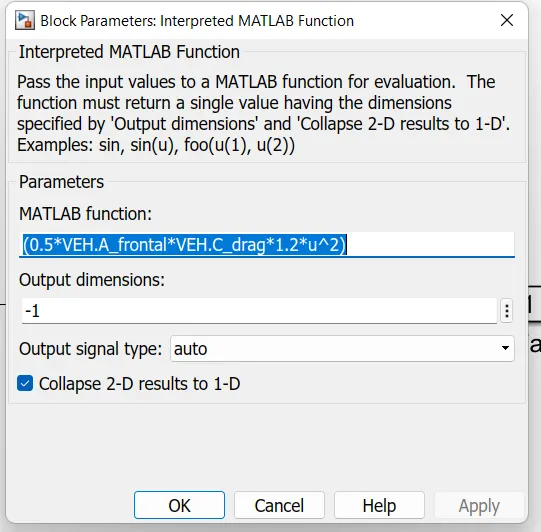
Air drage Resistance:
Hill climbing resistance:
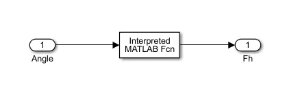
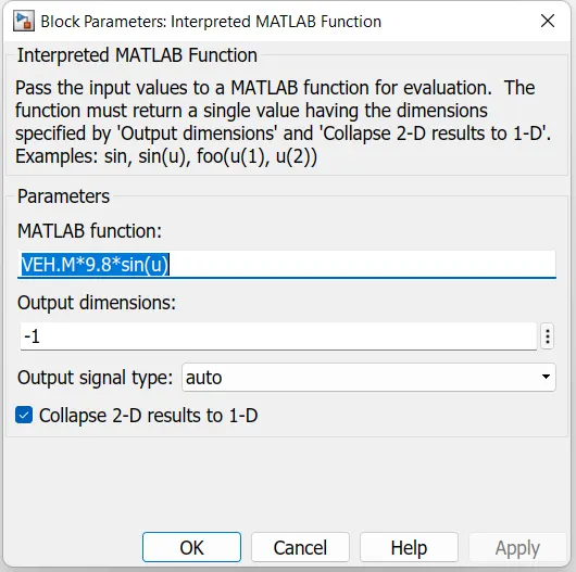
All these forces are added as shown above and subtraced from the Torque force. This resusltant force is divided by the Mass to get the acceleration of the vehicle
F = M*a
a = F/M
- a= acceleration of vehicle
- F = resultant force
- M = mass of the vehicle
This acceletion is integrated to get the velocity. The integratior is provided by a Level trigger to reset it beacuse to avoide the Integral Windup. When ever the velocity or Accelatrion of the driver pedal is zero the integrator shold be reset other wise it will get into Integral windup i.e., it goinh to take the previous value to avaluate and the even the velocity is zero the the out of integrator will increase.
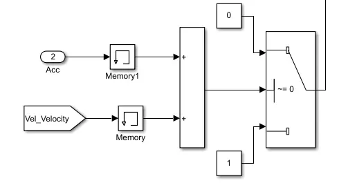
After integrating it we need to limit it for positive speed because the negitive speed will appeare when the Vehicle is going in reverse.
NOTE:
The block parameters which are not shown are taken as default values.
Before running the Model load the given Mat file in the workspace.
Outpurts:
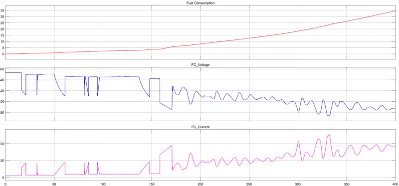
1st graph shows the H2 consumption. At the end of the cycle for 400 sec the total H2 consumption is a 34.68 kg.
The Voltage is around 280 to 360 V accoring to the power demand.
the current is aroun 0 to 120 A according to the Power demand.
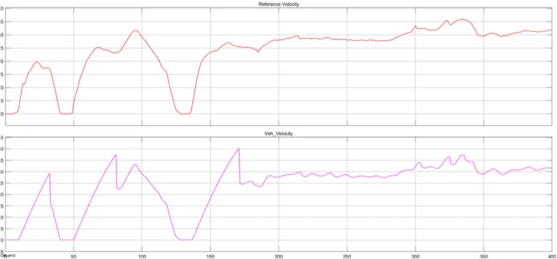
The 1st graph shows the input - referance speed and 2nd graph shows the output - vehicle speed, which is almost similar to the input. This indicates that the vehicle is following the input speed.