Project 2
ELECTRICAL DEFINITION
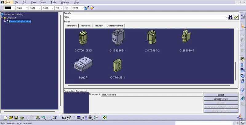
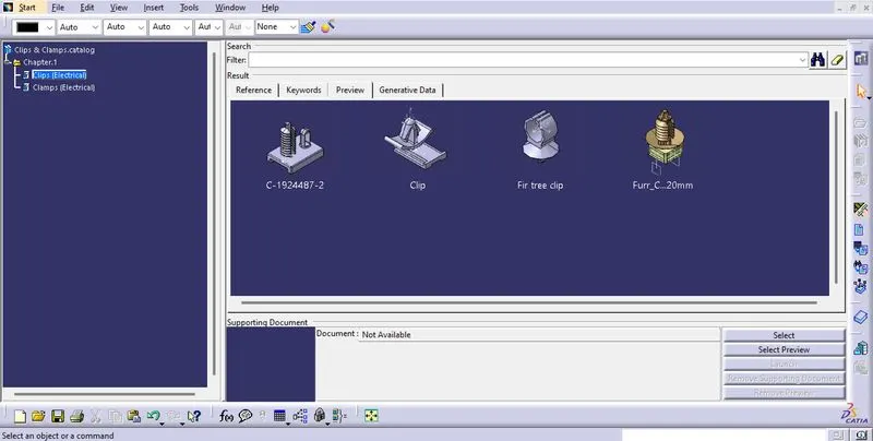
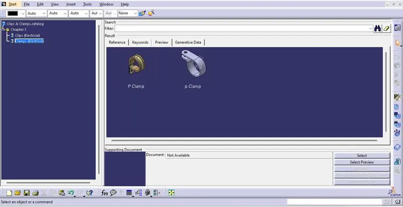
- There were previously defined components added to the catalogues.
- Therefore they were used for routing the backdoor.
COMPONENT PLACEMENT
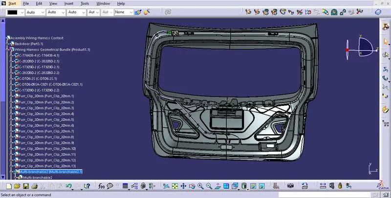
- I used 7 connectors in total.
- Interconnection connector - 1
- Tail lamp connector- 2
- Plate lamp connector - 2
- Latch connector - 1
- Windshield wiper connector - 1
- All these connectors were positioned tentatively on the backdoor.
- Clamps were also positioned at suitable positions.
ROUTING
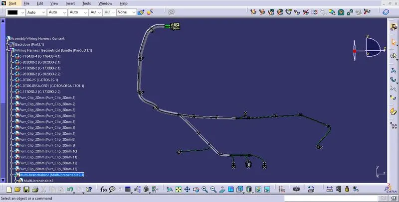
- Once all the components were placed, the product file was defined as a geometric bundle in the wiring harness workbench.
- A multi-branchable was also defined.
- Bundle segments, branching points and sub branches were defined.
- Sufficient slack was provided for bundles connecting to connectors.
- Special attention was given to preventing fouling.
- Ample number of clips were provided for connection.
- Poke-Yoke was applied for the plate lamp connectors.
- The minimum distance parameters for branching points and clips were satisfied.
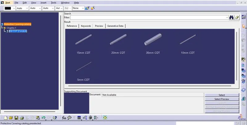
- Protective covering was applied.
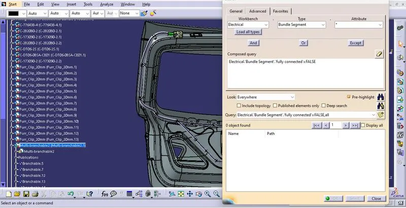
- The bundle was checked for full connectivity which was found to be satisfactory.
FLATTENING
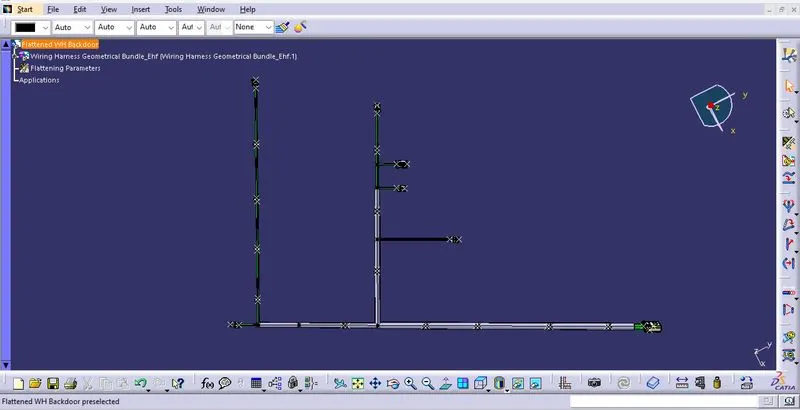
- A new product file was created for flattening and was opened in the flattening workbench.
- All flattening parameters were defined.
- Then the harness assembly was extracted and flattened.
- The sub branches positions were altered using the rotate command.
DRAWING
- A new drawing file was created.
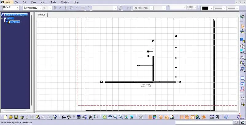
- The flattened harness was projected on to the drawing by selecting the view.
- In order to view the bundles, the properties were altered to change the visibility of wireframe.
- The drawing was scaled down to fit the sheet size.