Project 2
PROJECT 2
Aim: The main aim of this project is to gain the knowledge about the concept of design and analysis of an industrial building when subjected to the loading like lateral force such as wind and earthquake forces is understood and the various parameters that are to be taken into consideration while designing of an industrial building is learnt. And to determine the sizes that are required for the building to taken up the foces that are coming on to it.
Ans: MODELLING PROCEDURE
- As soon as the STAAD software is opened the analytical model is selected and then the units that are used for load and distance measurement are selected and then the file is saved at the appropriate location.
- Next the nodes are created with the help of the structure node option that appears at the right side of the screen. In that the co-ordinates are entered in the format of X, Y, Z system. Where the X is along the horizontal direction and Y is along the vertical direction and Z is also along the horizontal direction. For example if the node as to be created at a distance of 5m in the X direction then the co-ordinated would be 5, 0, 0. The same procedure is adopted to model the entire frame. In case of repetitive distance measurement then the particular node is selected and the transitional repeat option is used to repeat the number of operation.
- Then these nodes are connected with each other with the help of the add beam option which helps to create the beams and columns and rafter. The beams are connected as per the requirement. The beams can also be repeated with the help of the transitional repeat option or with the help of the copy beam option.
- Thus the structure that is required is modelled. The extra beams that are not required are deleted.
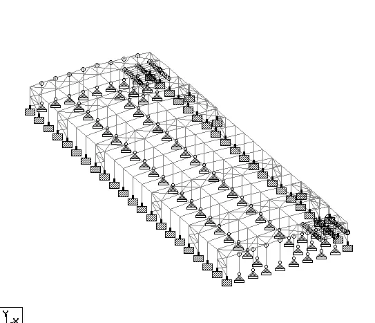
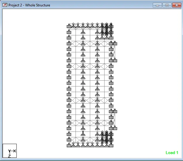
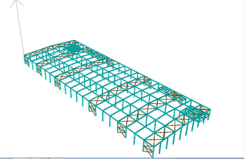
ASSIGINGING MEMBER PROPERTY AND SUPPORT PROCEDURE
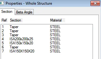
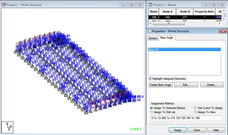
- In order to assign the member properties to the members select the geometry command, under that select the property command. A dialogue box appears. In the dialogue box select section data base for the steel structure. Then select Indian. Under that the various sections that are available in the market are displaced.
- After selecting Indian it provides various sections for all shapes of the sections. The different shapes available in the steel sections are I sections, Angle sections, Channel sections, Tube sections etc.
- The members that are required for the structure are selected and then the add option is selected which appears at the bottom of the window.
- In the same manner all the member properties that are required from the different shapes are add to the chart.
- Then each member property is selected and it is assigned to the members as per the question given. For example ISMB500 has been asked to assign to the columns. The property ISMB500is selected first and then the columns are selected.
- After that the assign to the selected beams option is selected which appears below the dialogue box is selected. Thus the property ISMB500 is assigned to the columns.
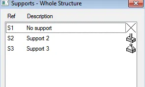
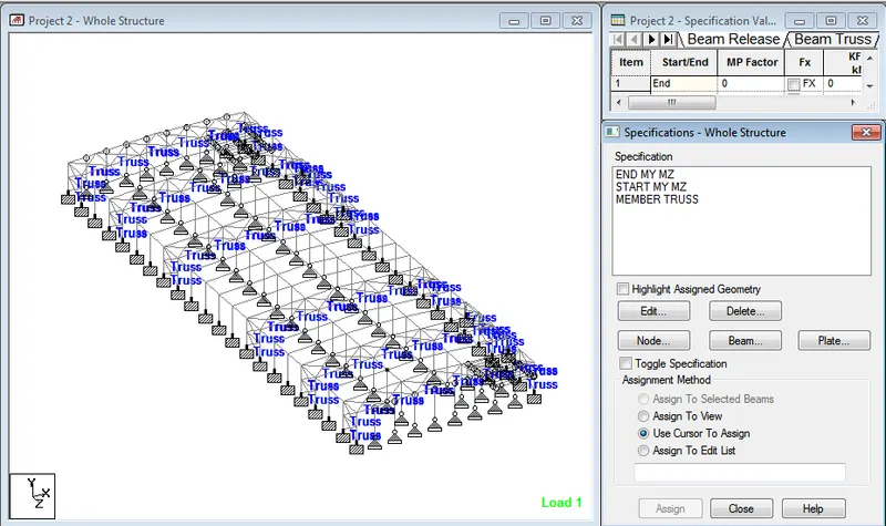
- Then the support to the columns should be assigned. Under the geometry section Support command is selected. A dialogue box appear, in that create option as to be selected. Then the dialogue box with various support conditions appears like fixed, pinned etc. as per the requirement fixed and pinned support condition are to be selected and then the add button is clicked.
- The fixed support are assigned to the exterior columns and the pinned support are assigned to the interior columns.
DEFINING LOAD AND LOAD COMBINATION PROCEDURE
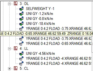
- In order to define the loads go to the loading option under geometry and select the load case option and define the loading types as dead load and live load. Name dead load types as DL and live load type as LL
- Now select DL and click on the add button to add that comes under DL. As per the given question the DL are 1.53kN/m for rafter and LL of 0.375kN/m for rafter.
- For 1.53kN/m and 0.375kN/m select the command as uniform force from the loading command and enter the value of the load with negative sign so that the load acts in the downward direction.
- Click on the load to be assigned and then select the member for which the particular load as to be assigned and the select the assign to the selected beams or nodes.
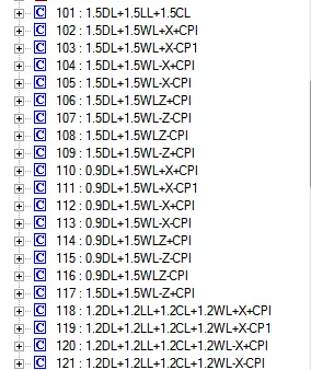
- In order to define the load combination select the command option and under command option select loading, under loading there is a option called load combination select that. Then the dialogue box appears with the load that we have defined. Select DL and LL and give the factor as 1.5 for both DL and LL. Save the combination with appropriate name.
Calculation of Design Loads
- Dead Load
- Dead Load on Rafter
- Weight of Roof Sheet = 5 Kg/m2
- Weight of Purlin and sag rods = 5 Kg/m2
- Additional weight = 5 Kg/m2
Total weight of rafter = 15 Kg/m2
Dead load on rafter = 15 x 10 x 8 = 1200 N/m = 1.2 kN/m
Dead Load on Purlin = 10 x 10 x 8 = 800 N/m = 0.8 kN/m
Mezz Slab self-weight (150 mm thk slab) = 0.15 x 25 kN/m3 = 3.75 kN/m2
Floor Finishes and additional load on Mezz Floor = (150 + 500) kg/m2 = 0.65 kN/m2
Weight of 230mm thick brick wall (4-meter height) on Mezz floor = 20 kN/m3 x 0.23 x 4 = 18.4 kN/m
- Live Load
Live Load on Roof and canopy = 57 kg/m2 x 10 x 8 = 4.56 kN/m
Live Load on Mezz Floor = 400 kg/m2 = 4 kN/m2
- Collateral Load
Collateral Load on Roof
- Load of Electrical fittings = 0.1 kN/m2
- Load of Sprinklers = 0.03 kN/m2
- Load of rockwool Insulation and bubble wrap insulation = 0.15 kN/m2
- Load of Solar Panels = 0.15 kN/m2
- Load of Ceiling = 0.1 kN/m2
Total Collateral load on Roof = 0.53 x 8 = 4.24 kN/m
Collateral Load on Mezz Floor (due to false ceiling & electrical fittings)
= 0.2 x 8 = 1.6 kN/m
Collateral Load on column due to Bracket Beam
Load due to service line supported on the beam spanning 8 m width= 150 kg/m x 8 x 10 = 12 kN
Moment acting on column due to service line = 12 x 0.75 = 9 kNm
Collateral Load on Jack Beam due to service line= 2.5 kN/m
Collateral Load on Mezz False Ceiling = 3.2 kN/m
- Wind Load
Basic wind speed = 50 m/s for chennai
K1 - 1.00
K2 - 1.05 (Terrain Catogory-1. Building height at eaves = 10.50 m)
K3 - 1.00
K4 - 1.00 (For other structures)
Coefficient of cyclonic wind may be taken as 1,
Kd -0.9
Ka (Rafter) - 0.8 or as per tributary area.
Ka (Column) - 0.8245 or as per tributary area.
Ka (Purlin) - 0.9721 or as per tributary area.
Ka (Side Runner) - 0.978 or as per tributary area
Kc -0.9
Design wind pressure = pd = kd x ka x kc x 0.6 x (Vb x k1 x k2 x k3 x k4)2 = 0.652 kN/m2
But should not be less than 0.7 Pz = 0.7 x 1.006 = 0.704 kN/m2
Cpe - As per table 5 & 6 of IS: 875 (Part 3) – 2015
h/w = 10/60 = 0.6
L/w = 170/60 = 2.83
Cpe On wall:
|
Direction |
A |
B |
C |
D |
|
0 deg. |
0.7 |
-0.25 |
-0.6 |
-0.6 |
|
90 deg. |
-0.5 |
-0.5 |
0.7 |
-0.1 |
Cpe On Roof:
Roof angle = 2.86
|
Direction |
EF |
GH |
EG |
FH |
|
0 deg. |
-0.86 |
-0.4 |
||
|
90 deg. |
-0.8 |
-0.4 |
Cpi = 0.2
Wind Load on Columns = (Cpe – Cpi) x A x Pd
Wind about X Direction + Cpi = (0.7 – 0.2) x 8 x 0.704 = 2.816 kN/m on Wall A
Wind about X Direction + Cpi = (-0.25 – 0.2) x 8 x 0.704 = -2.534 kN/m on Wall B
Wind about X Direction + Cpi = (-0.6 – 0.2) x 6.75 x 0.704 = -3.802 kN/m on Wall C & D
Wind about X Direction - Cpi = (0.7 + 0.2) x 8 x 0.704 = 5.069 kN/m on Wall A
Wind about X Direction - Cpi = (-0.25 + 0.2) x 8 x 0.704 = -0.282 kN/m on Wall B
Wind about X Direction - Cpi = (-0.6 + 0.2) x 6.75 x 0.704 = -1.9 kN/m on Wall C & D
Wind about Z Direction + Cpi = (-0.5 – 0.2) x 8 x 0.704 = -3.942 kN/m on Wall A
Wind about Z Direction + Cpi = (-0.5 – 0.2) x 8 x 0.704 = -3.942 kN/m on Wall B
Wind about Z Direction + Cpi = (0.7 – 0.2) x 6.75 x 0.704 = 2.376 kN/m on Wall C
Wind about Z Direction + Cpi = (-0.1 – 0.2) x 6.75 x 0.704 = -1.425 kN/m on Wall D
Wind about Z Direction - Cpi = (-0.5 + 0.2) x 8 x 0.704 = -1.689 kN/m on Wall A
Wind about Z Direction - Cpi = (-0.5 + 0.2) x 8 x 0.704 = -1.689 kN/m on Wall B
Wind about Z Direction - Cpi = (0.7 + 0.2) x 6.75 x 0.704 = 4.276 kN/m on Wall C
Wind about Z Direction - Cpi = (-0.1 + 0.2) x 6.75 x 0.704 = 0.475 kN/m on Wall D
Wind Load on Rafters = (Cpe – Cpi) x A x Pd
Wind about X Direction + Cpi = (-0.86 – 0.2) x 8 x 0.704 = -5.970 kN/m on Side A Rafter
Wind about X Direction + Cpi = (-0.4 – 0.2) x 8 x 0.704 = -3.378 kN/m on Side B Rafter
Wind about X Direction - Cpi = (-0.86 + 0.2) x 8 x 0.704 = -3.716 kN/m on Side A Rafter
Wind about X Direction - Cpi = (-0.4 + 0.2) x 8 x 0.704 = -1.125 kN/m on Side B Rafter
Wind about Z Direction + Cpi = (-0.8 - 0.2) x 6.75 x 0.704 = -4.752 kN/m Side C Rafter
Wind about Z Direction + Cpi = (-0.4 - 0.2) x 6.75 x 0.704 = -2.851 kN/m Side D Rafter
Wind about Z Direction - Cpi = (-0.8 + 0.2) x 6.75 x 0.704 = - 2.851kN/m Side C Rafter
Wind about Z Direction - Cpi = (-0.4 + 0.2) x 6.75 x 0.704 = -0.950 kN/m Side D Rafter
Wind Load on Canopy
Cp - As per table 8 of IS: 875 (Part 3) – 2015
Roof Angle 2.86 deg.
Cp -ve = 1.08
Cp +ve = 0.35
Wind Load on Canopy (Upward) = 1.08 x 8 x 0.704 = 6.082 kN/m
Wind Load on Canopy (Downward) = 0.35 x 8 x 0.704 = 1.971 kN/m
- Seismic Load
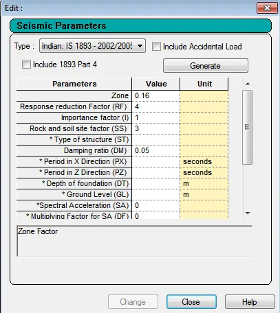
As per IS: 1893 - 2016
Seismic zone - III - Z = 0.16
Rf - 4.0
I - 1.0
SS - 3.0
25% of Live Load on roof considered for calculation of seismic forces.
100% of collateral load on roof considered for calculation of seismic forces.
50% of (Live load + Collateral load) on mezzanine floor considered for calculation of seismic forces.
100% of Dead load considered for calculation of seismic forces.
Conclusion:
From the project carried out it can be concluded that the concept of the design procedure of the industrial building of a PEB structure is learnt and the various loads that acts on the building during the lifetime of the structure is considered for the design of the building and the reasons for the failure of the same is learnt. The method for the determination of the size of the building components are learnt and the calculation of the lateral forces like wind load and the seismic force is also learnt. The design parameters that are to be considered while designing the steel and concrete structure is learnt.
Vijayalakshmi S H