Project 2
Aim:
To understand the model, perform geometry cleanup and choose proper mesh type for the each every component ( shell mesh or volume mesh) in the assembly. Also deploy the mesh for every component and deploy connections between various components in the assembly.
Procedure:
- First step is to open the model. This can be done by clicking on File > Open. Then the model will be loaded as shown below. Now the model should be checked for any geometric errors.
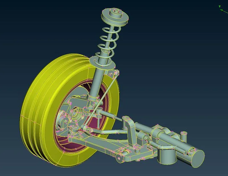
Fig :1 Showing Initial model
- For checking geometric errors, Click on Tools > Checks > Geometry. Then uncheck unmeshed macros and then click on Execute. This will result in displaying the errors in the geometry. Some of these errors can be fixed automatically which can be done by right clicking on particular issue and then click on fix option which will fix automatically. Remaining issues can be fixed manually with the help of options in TOPO module.
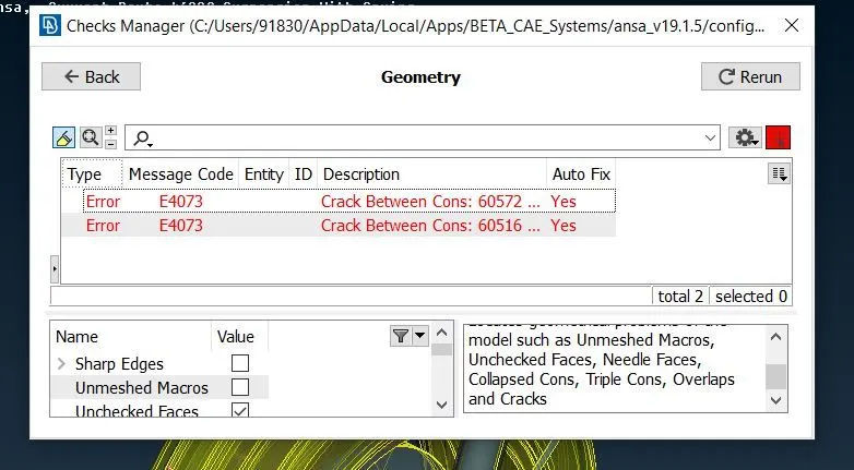
Fig :2 Showing errors in the given model
- After the geometry is free from all errors then proceed further by selecting type of mesh for the given component in the assembly.
- The selection can be done like, for non uniform components and components of more than 5 mm thickness proceed by using volume mesh (tet mesh) and for remaining components proceed by using shell mesh.
- After having proper idea of selection of mesh for various components, proceed further by extracting midsurface for the components where shell mesh is the best possible option. Extract the midsurf using Offset or Middle option in Faces tab in Topo module. After extraction of midsurface once again check for geometric errors and try to solve if found any.
- After the midsurface is free from errors, next step is to provide Quality criteria parameters and mesh parameters for performing Shell mesh.
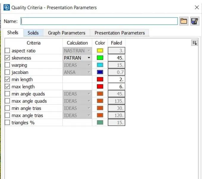
Fig :3 Showing the Quality criteria parameters
- Then proceed further by deploying shell mesh into the extracted midsurface. This can be done by using Spot mesh option in Mesh Generation tab in Mesh module. For achieving good mesh flow and no OFF elements, mesh needs to adjusted which can be done with the help of Reconstruct and Smooth options in Shell Mesh tab in Mesh module.
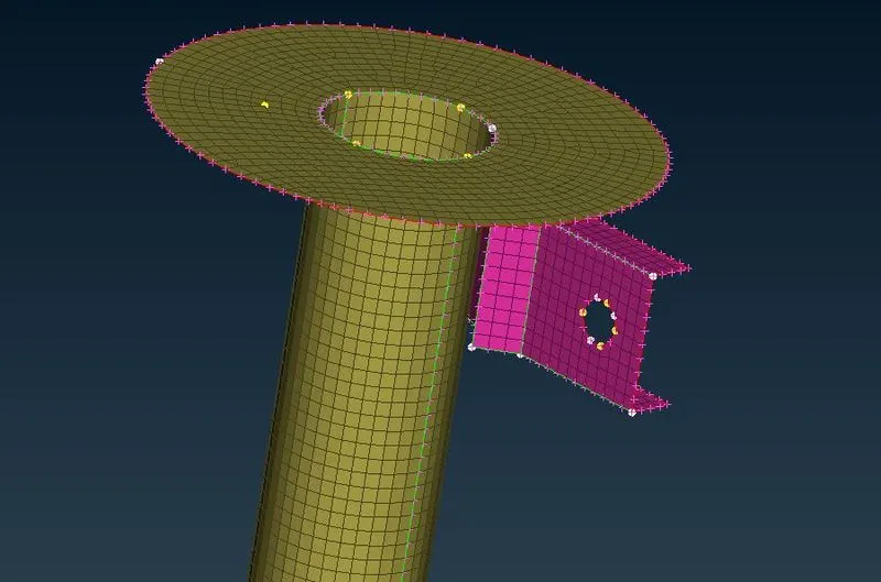
Fig : 4 Showing the Meshed components (Shell mesh)
- Next step is to deploy volume mesh for the components which are of non uniform thicknes type.
- For performing volume mesh, first we need to isolate the particular part then check for any geometric erros. If it is error free then proceed further by performing shell mesh. For performing Shell mesh we have to provide Quality criteria parameters and mesh parameters. For generation of Tet mesh, in mesh parameters tab we have to select tria instead mixed method. This will result in deploying only tria elements on the surface while performing shell mesh.
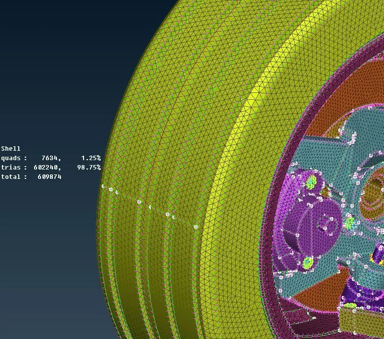
Fig : 5 Showing the Shell mesh generated for volume mesh
- Once the component is completely performed shell mesh, proceed further by defining volume. This can be done by clicking on Define > Manual option in Volumes tab in Volume Mesh module. For definition of volume PID needs to be generated i.e., PSOLID. The defined volume will appear in the list option in Volumes tab in Volume Mesh module.
- For performing Volume mesh, Click on the list. Then a window will pop up showing the defined volume having type (mesh type) and status whether it is meshed or unmeshed. Right click on the volume and then click on remesh option and choose mesh type like Tetra Rapid or Tetra FEM.This will result in generation of volume mesh.
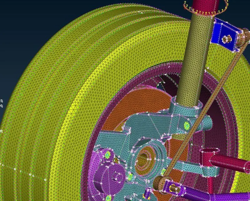
Fig : 6 Showing Meshed model (volume meshed)
- In this way each and every component in the assembly are deployed with volume mesh. whichever needs to be volume meshed.
- In this particular assembly , Tyre and Rim has specific quality parameters and remaining has other quality parameters which needs to be considered while deploying mesh.
- Next step is to deploy connections between various components. For connections, switch to Nastran deck. For representation of bolt, Multinode RBE2 is deployed at holes of two components whichever needs to be connected and a two noded RBE2 is deployed between the two master nodes at two holes.
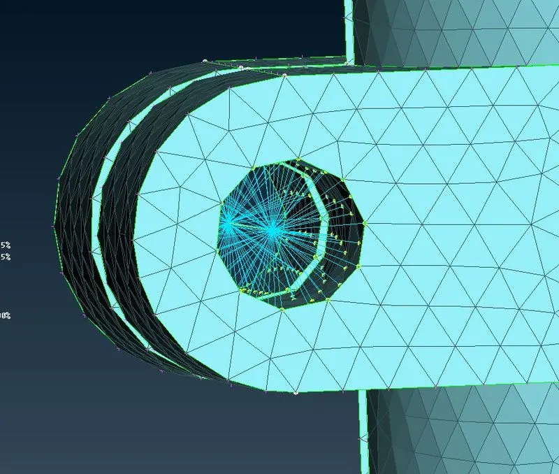
Fig : 7 Showing the Bolt connection (with Multinode RBE2 & 2 noded RBE2)
- For deploying the Seam weld connection, First we need to generate the curve where seam weld needs to be deployed. Use Feat2curve option in perimeters tab in Mesh module. click on this option and select the edges of elements upto which connection needs to be deployed. This process will result in generation of curve of length of elements edges.
- This generated curves needs to be converted into seam weld. This can be done by clicking on Assembly > Convert option.This will result in generation of seam weld line. Now this connection needs to be realised which can be done with the help of Connection manager.
- Click on Connection manager and select the parts whichever needs to be seam welded and keyin some parameters like weld thickness, step length etc. then click on apply and realize.
- Seam weld connection will be realized in the model between the selected parts.
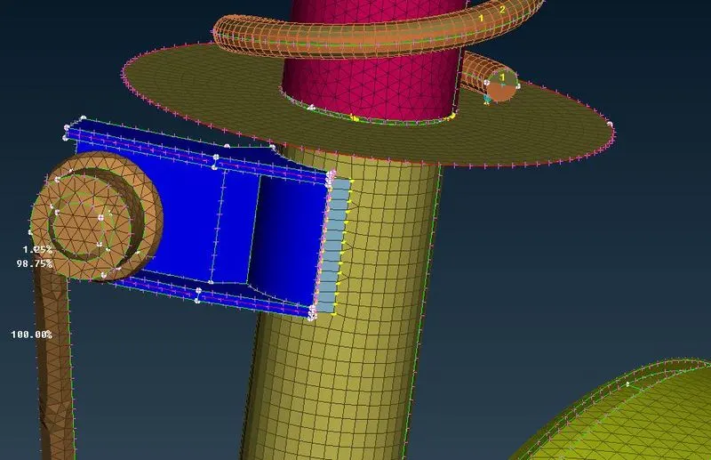
Fig :8 Showing the Seam weld connection
- After the completion of connections, Thickness of FE Model can be enabled by clicking on Draw shell as solid option in Presentation parameters in Quality criteria tab. 1D elements can be view by clicking on Line elements cross section > as solids.
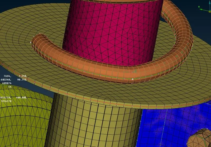
Fig : 9 Showing the FE model With Thickness
- Finally, Symmetry has to be performed on the model to get the other half of the suspension assembly. This can be done by using Transform > Copy > Symmetry. For symmetry use 3 point plane for defining symmetry plane.
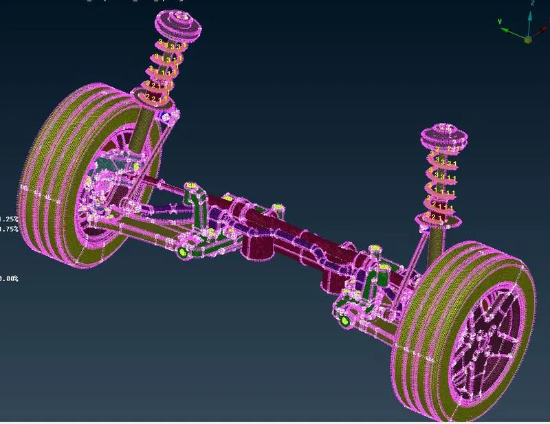
Fig :10 Showing the Final model
Conclusion:
Fig : 11 Showing initial model Fig : 12 Showing the Final meshed model with connections
Learning Outcomes:
- Geometry cleanup
- midsurface extraction
- performing shell mesh
- performing volume mesh
- deploying connections
- symmetry of model
Model Link:https:https://drive.google.com/file/d/1BuBQC34S08wfJbUih8rHJG3XCAcqoQ_W/view?usp=sharing