Project 2
Mathematical Modelling of the vehicle using Fuel Cell, Ultracapacitor and Battery
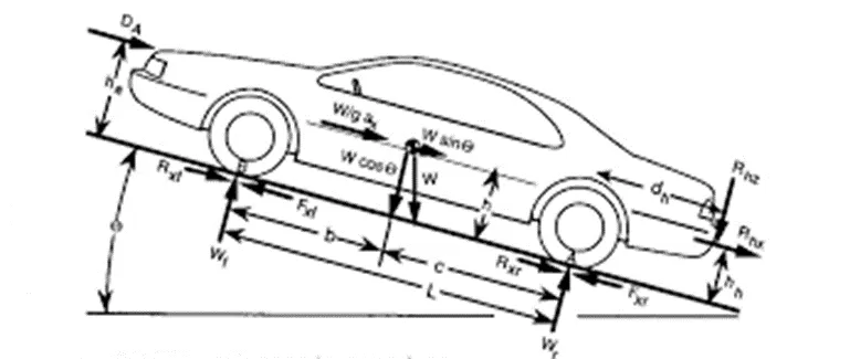
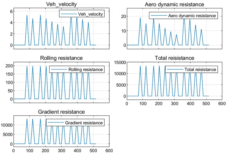
Forces acting on the vehicle are
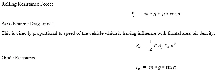
- Rolling Resistance Force
- Aerodynamic force
- Gradient force
Traction force is the sum of all the above forces.
Fte = Frr + Faero + Fg
Vehicle model:
The vehicle when moving on the road has forces acting on it.
When longitudinal forces and lateral forces are considered in a model, it becomes a 2D model.
The lateral forces are not considered for this model. (so it is called 1D model)
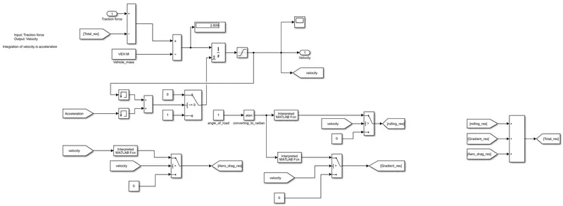
In the 1 D model of the Car, propulsion force and Opposing brake force, rolling resistance force, aerodynamic drag force, and gradient forces acting as opposing forces on the vehicle are considered.
The electric power train block does all the signal processing and generates a tractive/ Propulsion force.
This is then fed into the vehicle model block.
Tractive force propels the vehicle in a forwarding direction by overcoming the resistance it faces.
Vehicle parameters used in the model are:
|
M |
1900 |
|
A_Frontal |
2.86 |
|
C_Drag |
0.417 |
|
C_roll_res |
0.015 |
|
r_tire |
0.3305 |
|
Brake_F_proper |
0.6 |
|
Brake_R_proper |
0.4 |
Input to the vehicle model is from the Electric power train block and Driver block.
Driver Block:
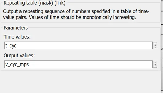
Driver block is taking the input signal from the user-defined block.
The repeating sequence is taken with two input values: t_cyc and v_cyc_mps.
Where t_cyc and v_cyc_mps are defined in the workspace.
Simulation of the Driver block:
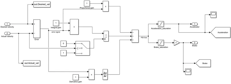
The desired velocity is compared with the actual velocity. If there is an error, the error correction is done with PID controller. If there is no error, them the correction is not required and it disables the integrator.
Compared output is given as input to the accelerator and brake saturations and after saturation the acceleration signal is considered for Acceleration and Brake saturation signal is considered for brake input.
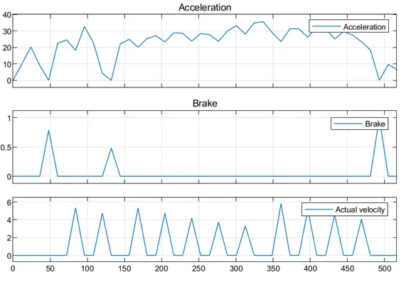
Scope shown is about the Acceleration Brake signal and velocity of the vehicle.
Electric power train:
This block contains the different energy sources and the Energy management system. Also, the Energy storage system.
Accelerator/ Brake block:
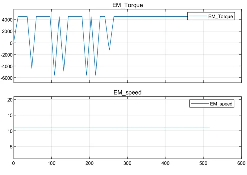
The torque input of the Electric motor is taken from the workspace.
Both positive and negative torque.
Electric motor data is considered from the database:
Gearbox ratio; gearbox efficiency; maximum torque, minimum torque, mass of the EM, max power etc.,
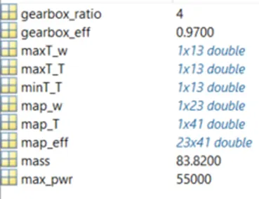
Torque inputs are taken from workspace. (No physical model)
Max torque is considered for acceleration and min torque considered for brake.
For power calculation, P=Tw is used.
Torque is one input and angular velocity is other.
Angular velocity is taken from front wheels.
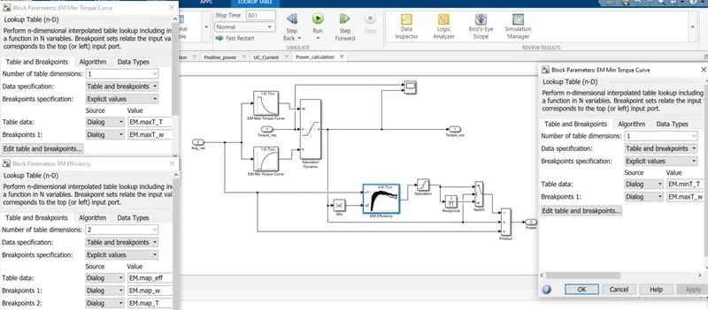
Torque request is verified with the Max torque and Min torque values. The torque chosen should not exceed the max limit.
Saturation dynamic block used to control the torque limits.
Power calculation is developed comparing with the Electric motor efficiency and its saturation levels.
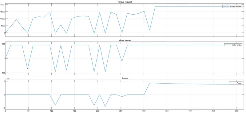
Tractive Force Block:
Torque is given as input to the EM gearbox.
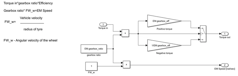
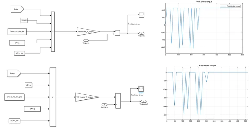
Front brakes block; Followed by rear brake torque
It is a product of brake, vehicle mass, ground friction, gravity, tire radius.
The product outcome is multiplied by using gain block.
Front brake torque is as shown below.
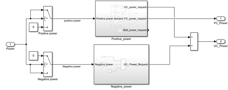
The energy management block is the development of the simulation model that takes the input from power and gives the input to the Fuel cell and Ultracapacitor.
A positive power block consists of sections that gives a comparison of power ranges and the energy usage inputs.
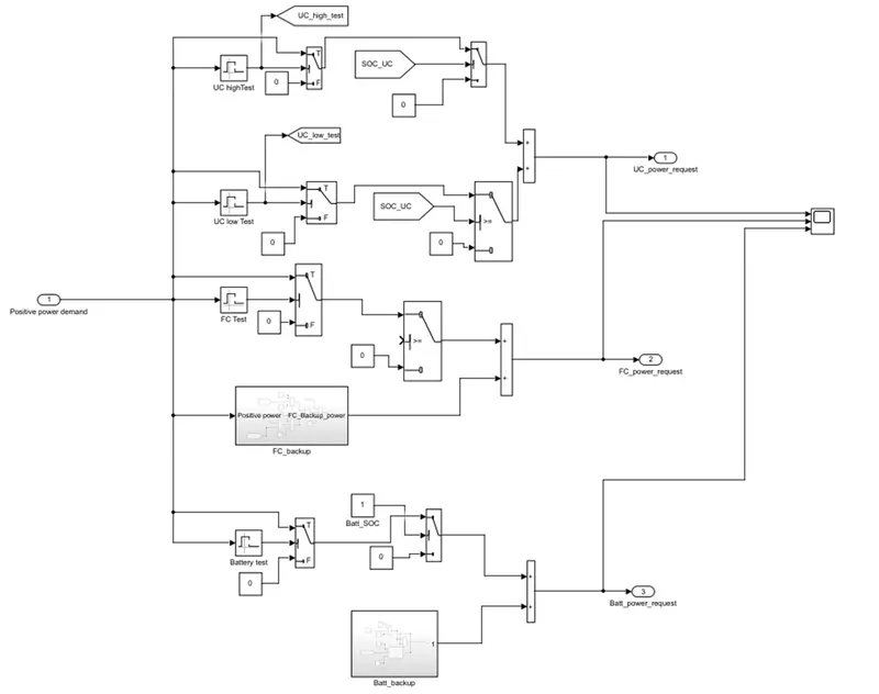
The fuel cell block consists of fuel cell power inputs.
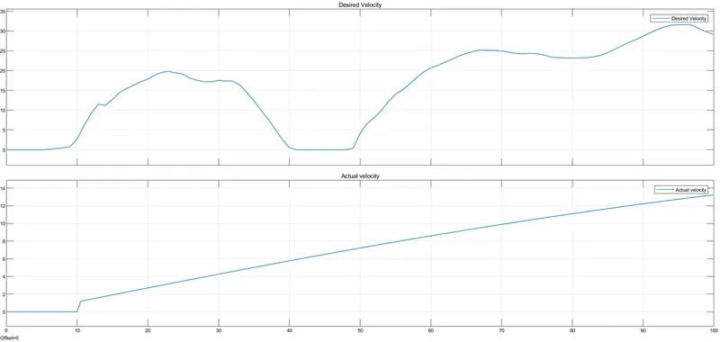
The overall model gives the output result for desired velocity and actual velocity.
Below is the comparative plot.