Project 2
AIM:-
- Design a DC power supply using PFC circuit for general purpose applications with 350V dc output and load in the range of 0-7A. The supply should meet the harmonic standard limits for input power quality such that current THD limits are satisfied with input power factor >0.97 value. The input side is connected to single phase grid with parameters as 230V, 50Hz.
Design the supply to give following specifications:
- Component selection and justification
- Passive component designs including filters
- Controller design
- Simulation results
- Validation with the design criterion
- Redesign the above power supply with the PWM rectifier. Give the difference in both power supplies in terms of cost, control complexity, degrees of freedom, additional features and efficiency.
PFC circuit:-
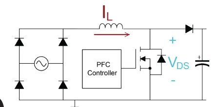
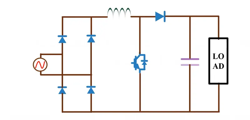
PFC techniques are broadly divided into passive (static) PFC, partial-switching PFC, and active(switching) PFC. Passive (static) PFC inserts a reactor in series with a power supply. Depending onthe capacity of the power supply, a large reactor is required. Therefore, passive PFC is commonlyused for low-capacity power supplies
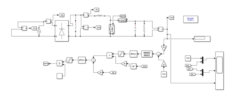
Simulink model
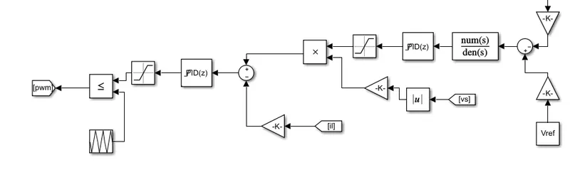
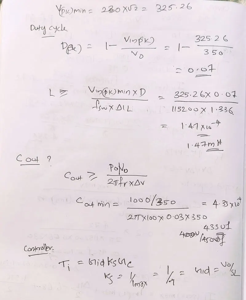
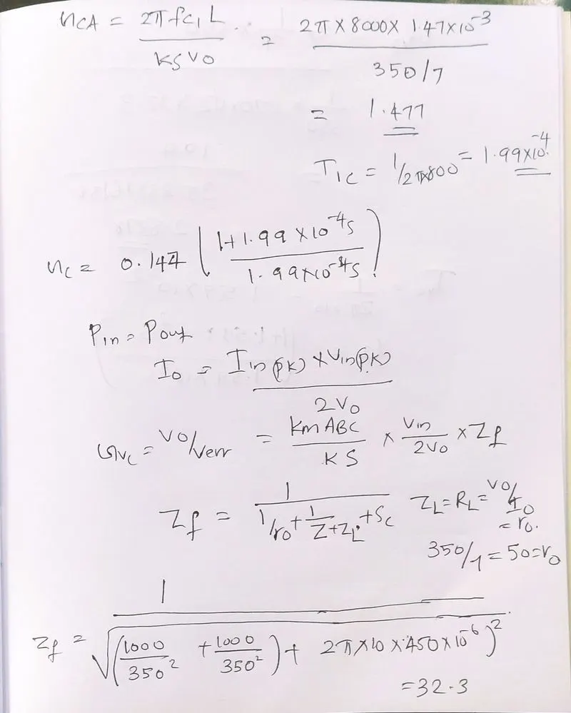
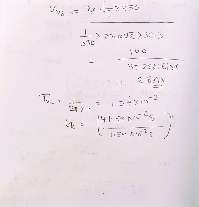
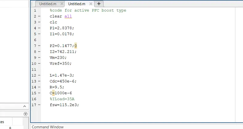
Controller design:-
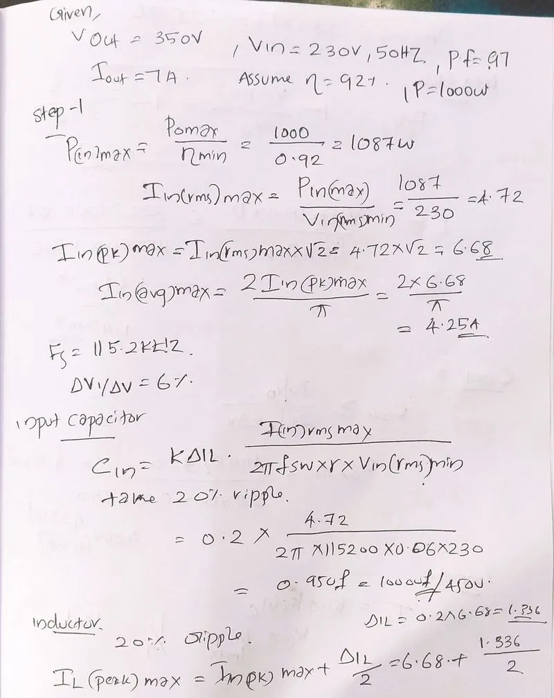
Calculations:-
Results:-
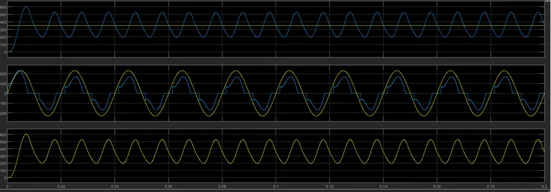
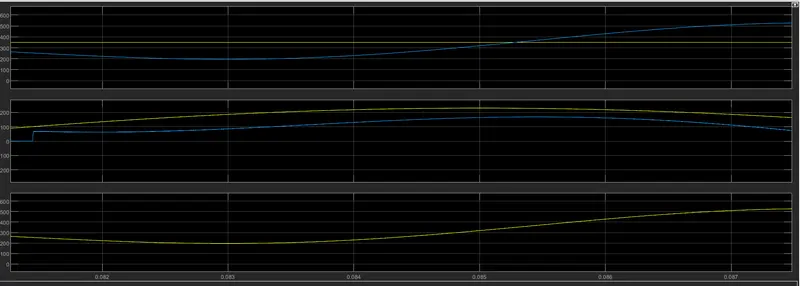
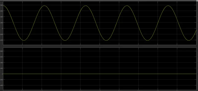
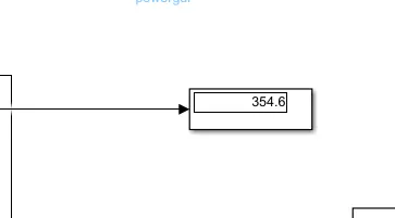
output voltage
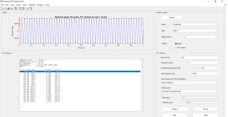
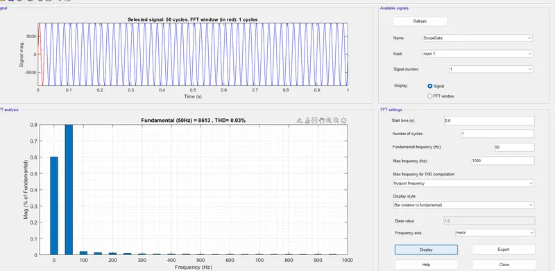
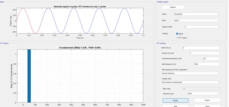
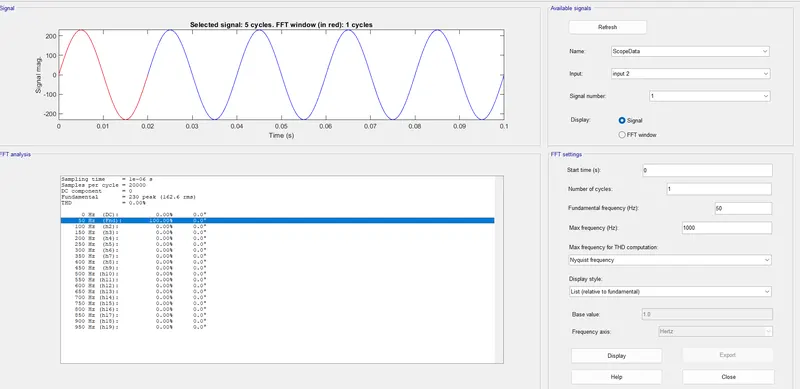
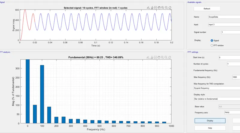
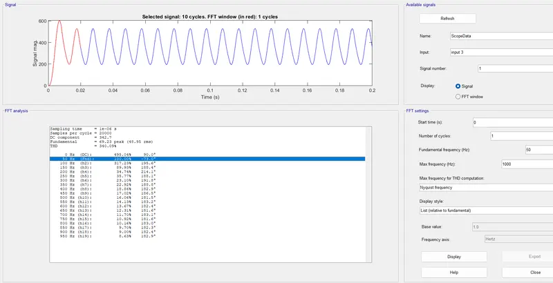
FFT analysis
Design a high-performance high voltage DC power supply for 15 kV dc output and load in the range of 0-10A. The supply should meet the harmonic standard limits for input power quality such that current THD limits are satisfied with input power factor >0.98 value. The input side is connected to three-phase LV grid with parameters as 11kV (line-line), 50Hz.
Design the supply to give following specifications:
- Component selection and justification
- Passive component designs including filters
- Controller design
- Simulation results
- Validation with the design criterion
SIMULINK MODEL
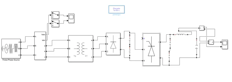
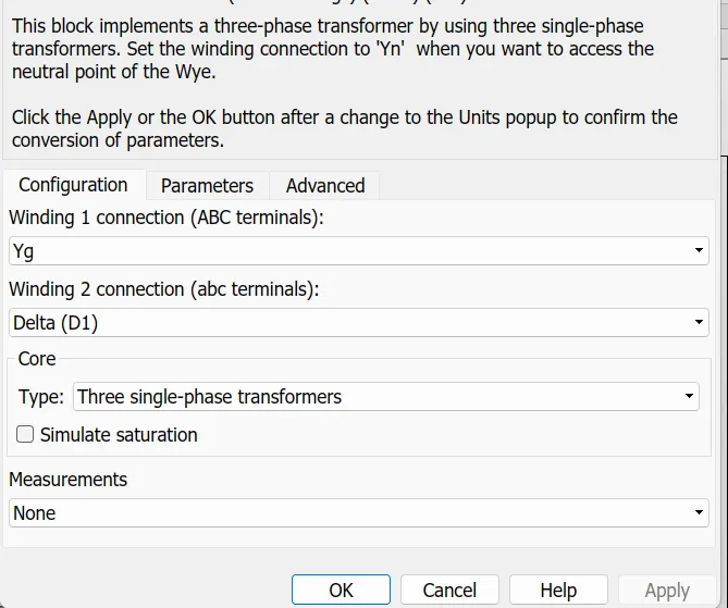
we knoe here 3 phase line voltage is 11kv (11000v) so we cant give this voltage directly in bridge we need to step down the voltage by using a 3 phase 2 winding transformer
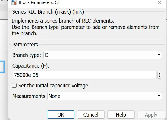
after we need to transfer that voltage in to bridge rectivier dc link capacitor need here 2 capacitor csed
again we need to transfer to a bridge rectifier. now usin thyristor rectifier because opareting high voltage ,and also we need high output voltage
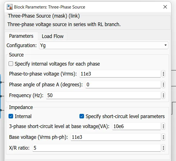
Ac source
Transformer
Capacitor
Results
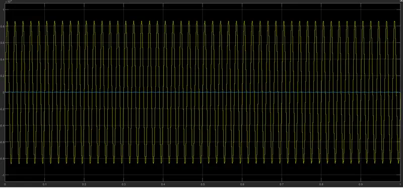
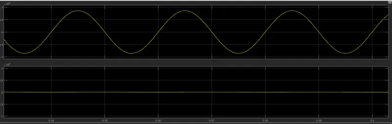
output