Project
Aim:-
To study,analyze and make a detailed report on BAJAJ ALL TERRAIN VEHICLE (ATV) using simulink
Objective:-
Prepare a technical report explaining the model and properties and comment on the result
Introductions:-
ALL TERRAIN VEHICLE(ATV):-
All terrain vehicle(ATV)is defined as motorized off-highway vehicle designed to travel on four low-pressure or non-pneumatic tires,having a seat designed to be straddled by the operator and handlebars for streering control.ATVs are subdivided into two types.the type1 ATVs are intended by the manufaturer for use by a single oparator and no passenger.ans the type2 ATVs are intended by the manufaturer for use by a oparator and a passenger.
Continuosly variable transmission(CVT):-
A continuosly variable transmission(CVT)is anautomatic transmission that can change seamlessly through a continuos range of gear ratio.this contract with another transmission that provide a limited number of gear ratio with fixed step.the flexibility of a CVT with suitable control may allow the engine to oparate at the constant RPM while the vehicle moves at varying speed
Basic simulink block used:-
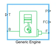
the generic engine block represents a general internal combution engine.the engine type include spark-ignition and diesel.speed-power and speed torque parameterizations are provided.a throttle physical signal input specifies the normalized engine torque.optional dynamic parameter includes crankshaft inertia and response time lag.a physical signal port output engine fuel consuption rate based on choice of fuel consuption model.optional speed and redline controllers prevent engine stall and enable cruise control.
Main ports:-
1. B-rotational conserving port:representing engine block.
2. F-rotational conserving port:representing engine crank shaft.
3. T-physical signal input port.
4. P-physical signal output port.(reporting instantaneous engine power,inW)
5. FC-physical signal output port(fuel consuption rate)
Simple gear:-
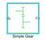
B-base:rotational mechanical conserving port associated with the base or input shaft
F-follower:rotational mechanical conserving port associated with the follower or output,shaft
Variable ratio transmission block:-
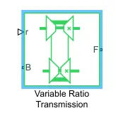
the variable ratio transmission block represents a gearbox that dynamically transfers motion and torque between the two connected drivershaft axes ,base and followers.
B-base pulley or driver pulley
F-follower pulley or driven pulley
r-variable transmission ratio(input)
Vehicle body block:-
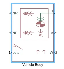
vehicle body block represents as two axle vehicle body in longitudinal motion.the vehicle can have the same or different number of wheel on each axle.
the block accounts for body mass aerodynamics drag road incline and weight distribution between axle due to accelaration and road profile.optionally include pitch and suspension dynamics.
the block has an option to include an externally-defined mass and an externally-defined inertia.the mass inertia and center of gravity the vehicle body can vary over the course of the simulation in response to system change.
Limitations:-
the vehicle body block lets you model only longitudnal dynamics.parallel to ground and orient toalong the direction of motion.the vehicle is assumed to be in pitch and normal equilibrium.the block does not model pitch or vertical movement,as such the equation assume that the wheel never lose contact.this constrain can result in negative normal forces.
Input ports:-
1.beta-road incline angle(rad)
2.W-head wind speed(m/s)
3.CG-center of gravity(m)
-M-mass(kg)
-J-moment of inertia(kg*m^2)
Output port:-
1.NR-rear axle normal force(N)
2.NF-front axle normal force(N)
3.V-longitudnal velocity(V)
conserving port:
H-horizontal motion :conserving port related to horizontal motion of vehicle body
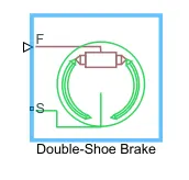
double shoe brake blok represents a frictional brake with two pivoted rigid shoe that press aganist a rotating drum to produce a braking action.the rigid shoe sit inside or out side the rotating drum in adiamertically opposed.
double shoe brake provide high braking torque with small actuator deflaction in application that include motor vehicle some very heavy machinery.the model employs a simple parameterization with readily accessible brake geometry and friction parameters.
Limitations:-
-contact angle smaller than 45degree produce less accurate result.
-the brake uses the long-shoe approximation.
-the brake geometry does not self lock
Input ports:-
F-physical signal input port associated with the rotating drum shaft
Conserving port:-
S-rotational conserving port associated with the rotating drum shaft
Tire(magic formula):-
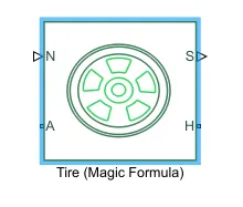
- the tire(magic formula) block models a tire with longitudinal behavior given by the magic formula,an empirical equation based on four fitting coefficient.the block can model tire dynamics under constant variable pavment condition.
- the longitudinal direction of the tire is the same as its direction of motion as it rolls on pavement.the block is a structural component based on the tire road intraction block.
- to increase the fidelity of the tire model we can specify properties such as tire compliance ,inertia and rolling resistance.however ,these properties increse the complexity of the tire model and can slow down the simulation.consider ignoring tire compliance and inertia if simulating the model in real time or if preparing the model for hardware-in-the-loop(HIL)simulation.
Other blocks used:-
1.solver configuration
2.signal builder
3.simulink to ps converter
4.ps to simulink converter
5.mechanical reference
6.rotational free end
7.scope
8.display
9.inertia
10.rotational motion sensor
11.ps terminator
12.ps constant
13.rotational free end
14.custom measure gauge
15.knob
16.lookup table
17.step
Simulink model:-
BAJAJ ATV MODEL WITHOUT DASHBOARD
Main model:-
Steps:-
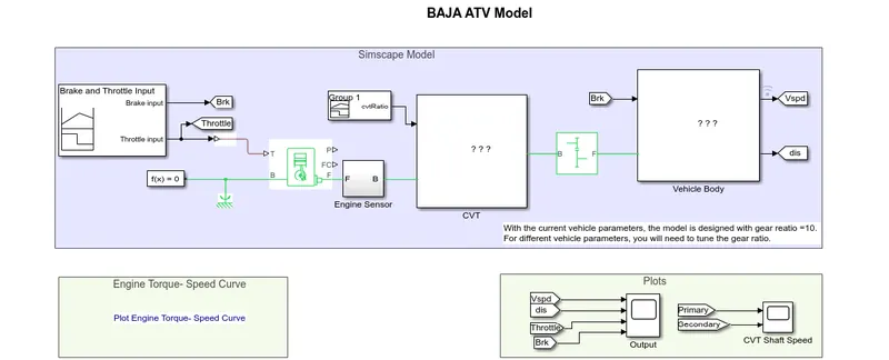
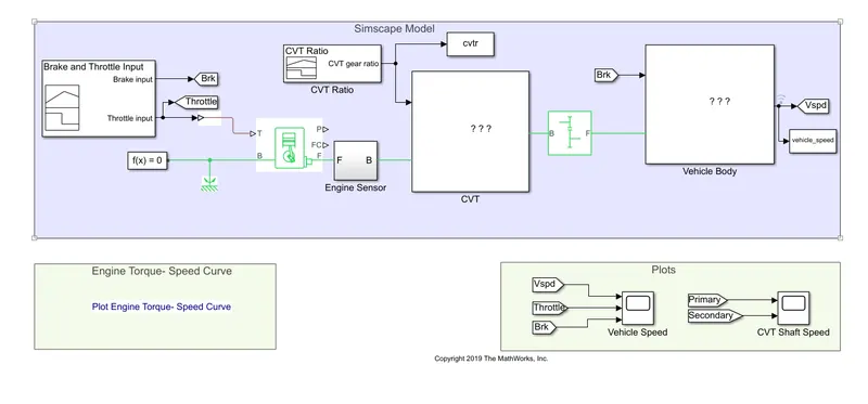
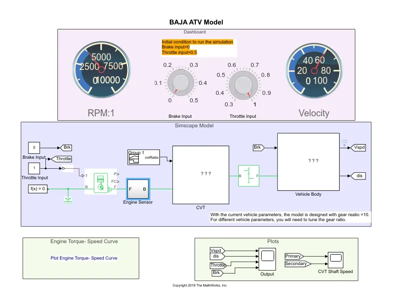
1.the throttle signal is generated by signal builder block and inputed to generic engine
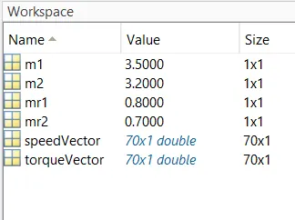
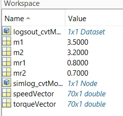
2.the torque and speed vector are inputed from the MATLAB workspace.
3.the engine will generate the output rpm which can be taken from the crank shaft output.this speed will given ideal rotational motion sensor to sense the output rpm.
4.the same output speed will be given to a simple gear mechanism to reduce the speed where gear ratio is 4
5.then the output speed from the gear reducer will be given to the variable ratio transmission(CVT) block.
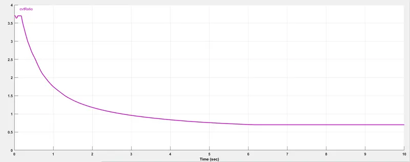
6.the cvt ratio is provided to the variable ratio transmission (CVT)block through signal builder.
7.the speed is controlled by the variable CVT ratio and controlled output speed is inputted in to vehicle axle.
8.the brake signal is generated by the signal builder and inputted to the vehicle body for applying the brake to axle.
9.the power from the CVT is inputted to the axle and the vehicle accelarates according to the speed.
10.then the velocity is taken as output from the vehicle for the further analysis
Torque and speed MATLAB workspace:-
Input signals:-
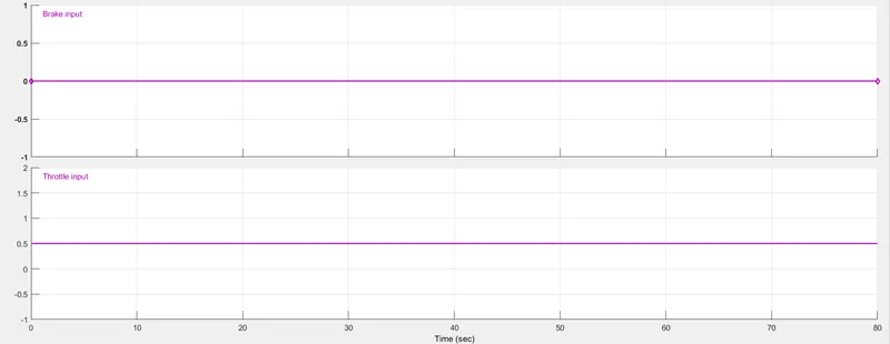
throttle input and brake input signal:
CVT ratio:-
Engine sensor sub block:-
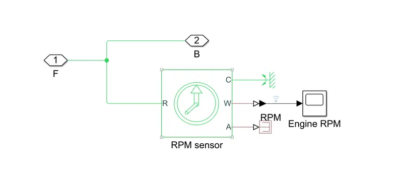
this block measure engine rotational speed as it takes the output of the engine as its input and outputs engine RPM
CVT subblock:-
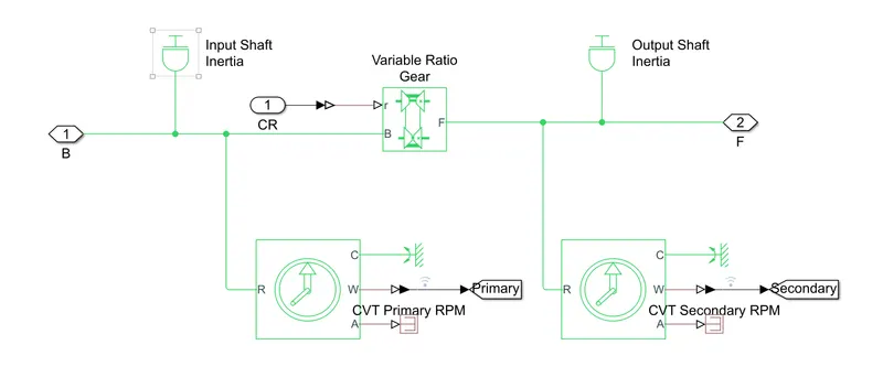
the CVT subblock provide the input and output shaft of the CVT with inertia and measure the input shaft rpm and output shaft rpm
Vehicle body subblock:-
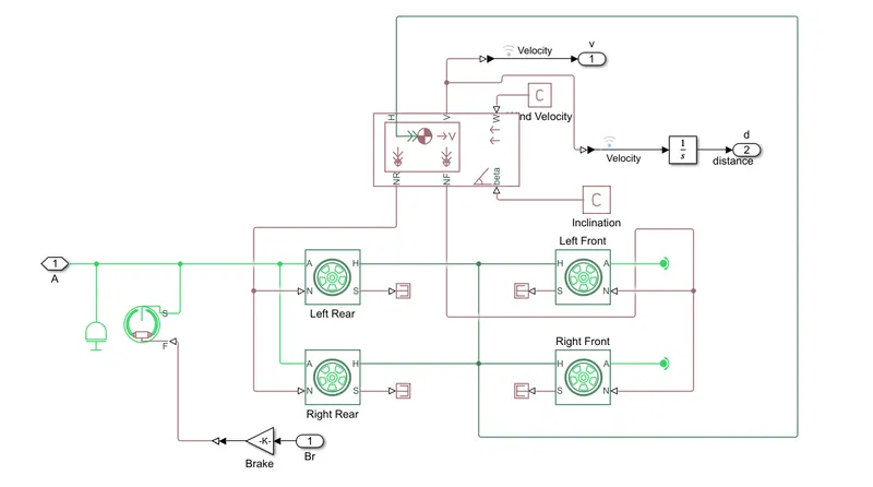
the model shows that vehicle is rear wheel drive as the output from the gear box is inputted to the rear axle,then an inertia is added to simulate axle inertia ,then the shoe brake s conserving port is connected to the axle,and the same axle is connected two rear tyres while the front tyre is free to rotate on a rotational free end.all the tyre H hub is connected to together and then connected to wheel H port also the rear tyres N port is connected to together and then connected to vehicle body Nr output ports the vehicle body takes the road inclination and wind velocity from physical constant.
Results:-
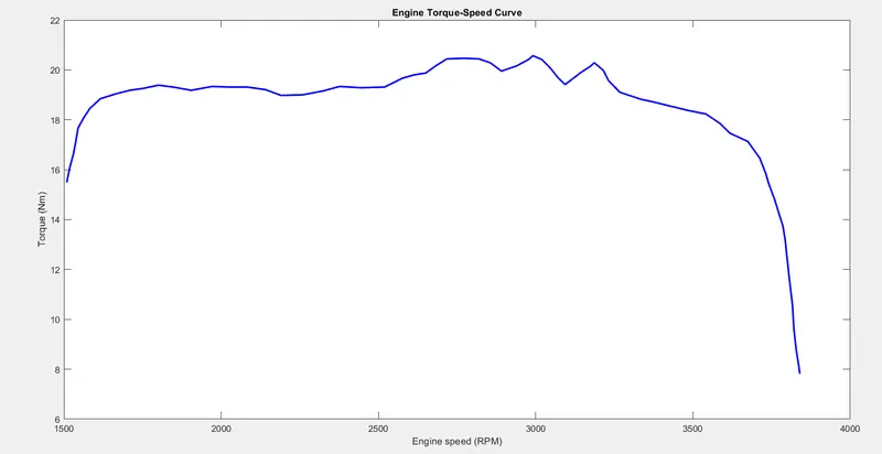
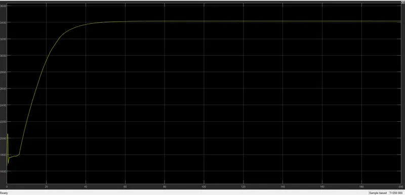
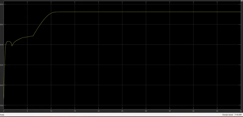
the torque and speed are inputted from the matlab workspace window.the generic engine block to generate the output rpm accordingily.this plot behaviour is generic to all ICE.
Engine RPM:-
output:-
CVT shaft speed:-
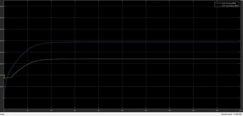
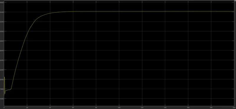
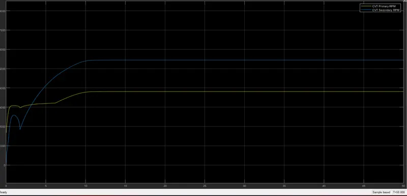
-initial velocity/rpm engine is defined as the 1750 rpm then the throttle value is constant input the rpm of engine changes accordingly.
-and since the throttle value is constant through the complete the simulation after a certain duration engine rpm become constant.
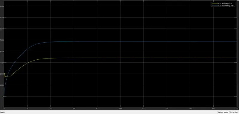
-as the primary shaft is connected to the engine it look similar to the engine but due to the inertia and the other factors the primary shaft rpm will not be the same as the engine rpm and it have some losses
-according to the CVT ratio the secondary shaft speed is achieved.
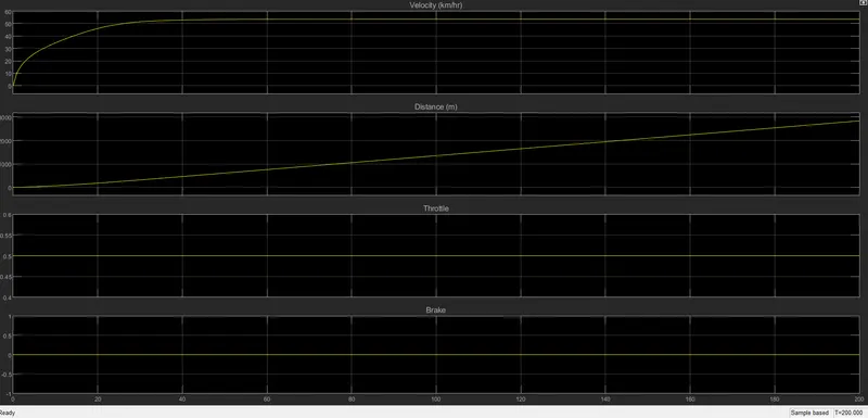
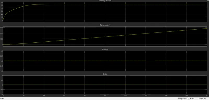
-we can the throttle value and brake value are constant during the complete simulation.
BAJAJ ATV MODEL-data extraction(CVT model-data):-
Main model:-
Steps:
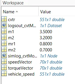
the model workflow process is same as the process of BAJAJ ATV MODEL dashboard.small addition here the cvt ratio and vehicle speed data are extracted using TO WORKSPACE block.
Results:-
MATLAB workspace:-
Vehicle speed:-
BAJAJ ATV MODEL with dashboard(cvt model-dashboard):-
Main model:-
Dashboard:-
User controls:-
Workspace:-
Results:-
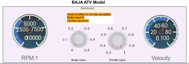
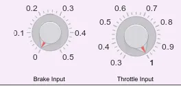
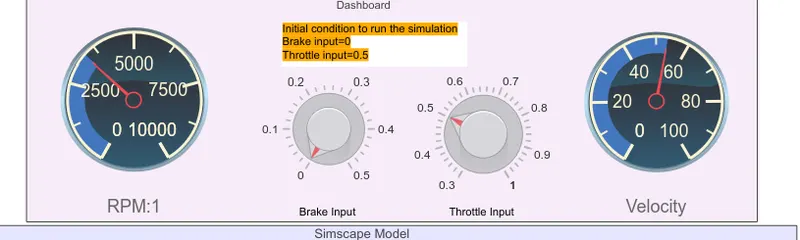
here brake=0,throttle=0.5
engine RPM:-
outputs:-
cvt shaft speed:-
BAJAJ ATV MODEL-Mapped lookup table without dashboard
dashboard(cvtmodel-mapped)
main model:-
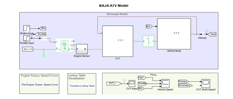
steps:-
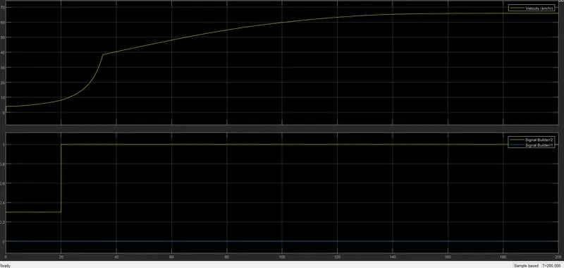
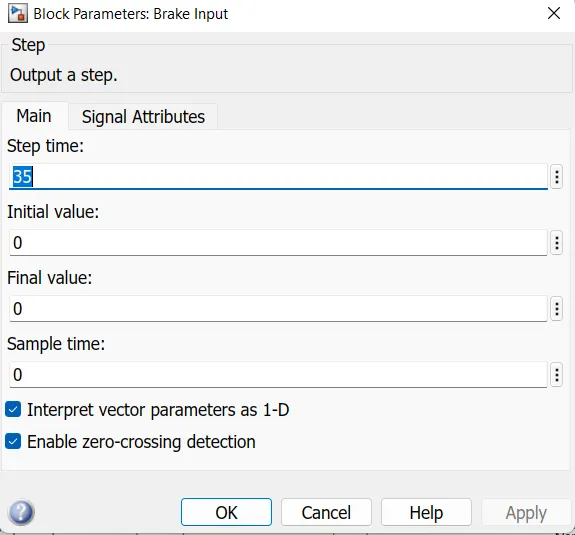
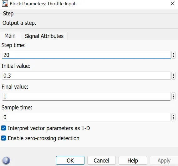
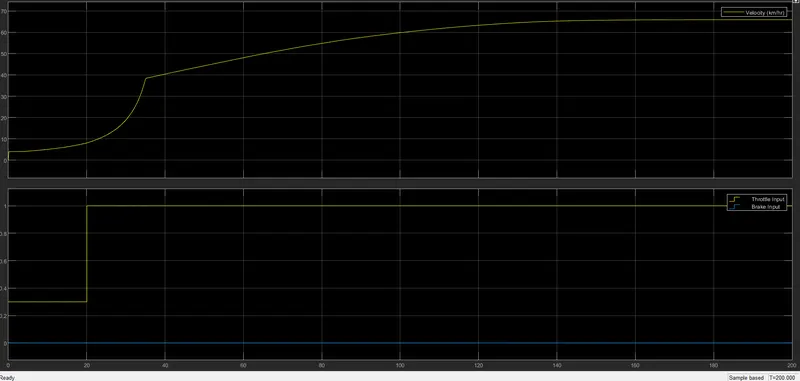
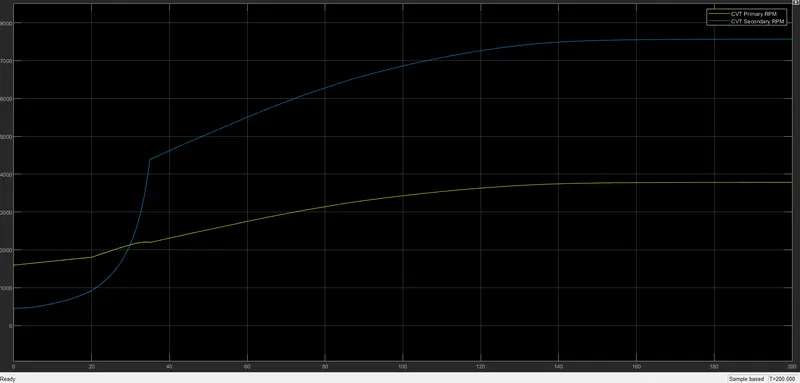
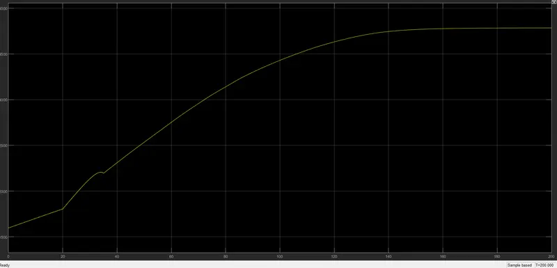
the model workflow process is same the process opf BAJAJ ATV MODEL WITHOUT DASHBOARD except that it used instead of signal builder block for brake and throttle input step input block are used.at 35sec the break input will be take a step of value 0 and 20 secthrottle input will be 0.3-1 then remains constant throughout.
CVT subblockl:-
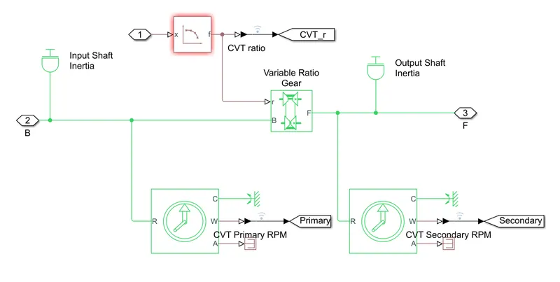
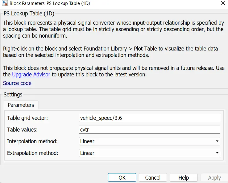
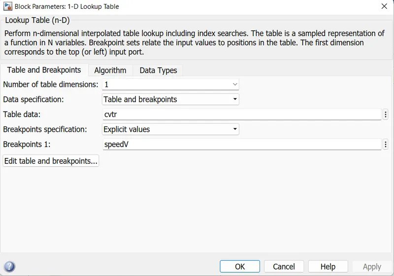
the CVT subblock is same as the previous model BAJAJ ATV WITHOUT DASHBOARD but instead of signal builder block for CVT ratio the 2D lookup table is usedit need to be loaded in the workspace having the file name as Lookuptable-data.mat
Lookuptable:-a lookup table is array of data that maps input value to output value thereby approximating a mathematical function.given as set of input value a lookup oparation retrieves the corresponding output value from the table.if the lookup table does not explicitly define the input value simulink can estimate an output value usin interpolation,extrapolation,or rouding value
-interpolation is a process estimating value that lie between known data point
-extra polation is a process estimating value that lie beyond the range of known data point.
-rounding is the process for approximating a value by altering its digits according to known rule.
Results:-
speed vs throttle
Shaft speed:-
Engine rpm:-
CVT ratio:-
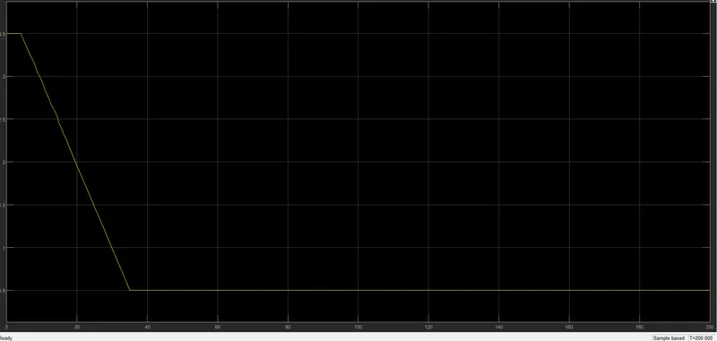
BAJAJ CVT MODEL(cvt-ratio)
main model:-
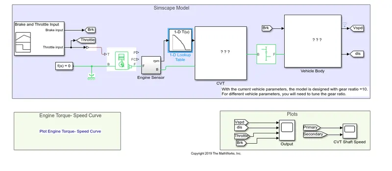
here we have a lookuptable
Results:-
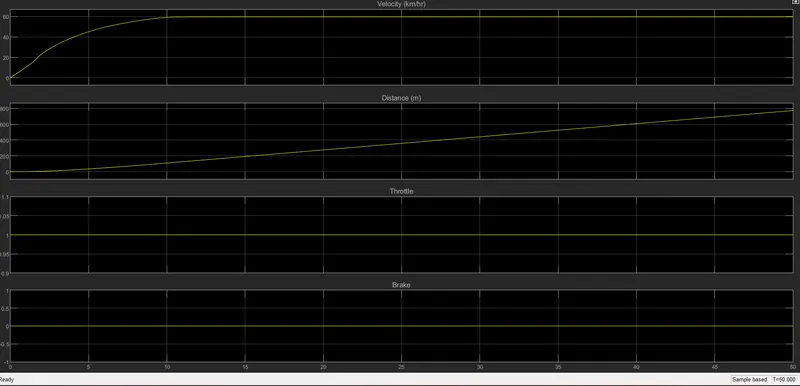
CVT shaftspeed:-
Engine rpm:-
Final conclusion:-
-We can understand easily how the vehicle may perform under the provided conditions.
-We are also able to observe the perfomance of the braking system and the throttle system.
-We can calculate the time required to attain a certain amound of speed or stop the vehicle completely.
- this model helps us to verify the perfomance of the vehicle under the constructed brake system and throttle system.