Rear Wheel Assembly - Shell / Solid Meshing + Connection Deployment
OBJECTIVE:
For the given component (Rear Wheel Assembly), check for the geometrical errors and mesh with the given element quality criteria. We need to excute 3 key tasks in for this model:
- For components having thickness greater than 5 mm - 3D - Solid Meshing
- For componests having thickness less than 5 mm - 2D - Shell Meshing
- Deploy connections as required.
SOLID MESHING:
Solid meshing Overview:
Solid mesh is also known as volumetric mesh used for components having thickness greater than 5 mm. There are 2 types of solid meshes:
- Structured Mesh:
Structured meshes are meshes with implicit connectivity whose structure allows for easy identification of elements and nodes. Often structured meshes have orthogonal quadrilateral (2D) or hexahedral (3D) elements.
- Unstructured Mesh:
Unstructured meshes are meshes with general connectivity (GCON) whose structure is arbitrary and therefore the connectivity of elements must be defined and stored. GCON element types are non-orthogonal, such as triangles (2D) and tetrahedra (3D).
SOLID MESHING of TYRE and RIM:
Now we solid mesh both tyre and rim with new given quality criterias:
| Quality Criteria for Tria Elements (Tyre and Rim): | ||
| S.No | Quality Criteria | Value |
| 1 | Target/Average length | 6.5 |
| 2 | Minimum Length | 5 |
| 3 | Maximum Length | 10 |
| 4 | Skewness | 45 |
PROCEDURE:
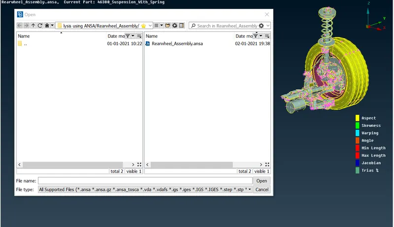
Import rear wheel assembly model into ANSA
GEOMETERY CLEANUP:
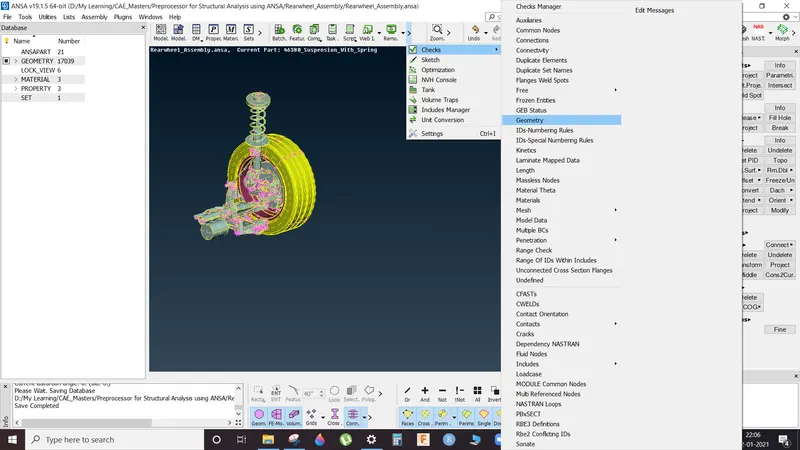
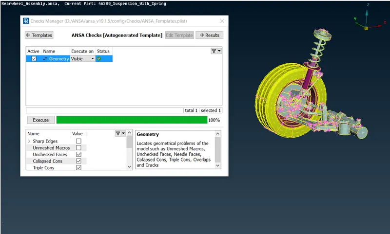
a) Use Auto-Fix to resolve errors.
b) If any error resolution is unsuccessful in auto mode then use manual method for cleanup by using release and TOPO tab in Faces section available in TOPO mode.
SOLID MESHING of COMPONENTS:
Since, the thickness is greater than 5 mm so we execute solid meshing of the components. Therefore, extraction of mid surface is not required and we proceed with 2D meshing on parent geometry surface.
- Select MESH tab from upper right-hand corner
- Press F11 to open quality tab and enter the given parameters
- Open Mesh Parameter tab and enter target, minimum and maximum lengths.
- Make user defined cuts using CUT tab as needed.
- Here we use SPOT MESH with normal tria and ortho tria elements (options list in below righthand corner) for solid unstructured mesh generation (Shell Meshing):
Flat areas: Normal Tria Elements:
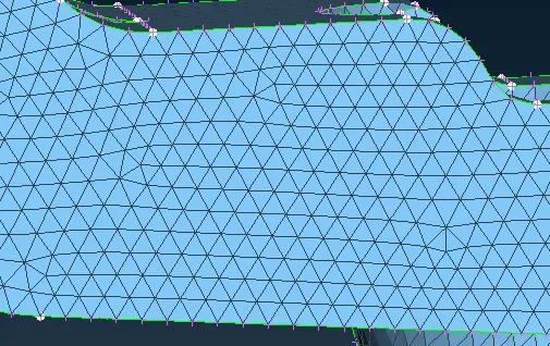
Curved areas: Ortho Tria Elements:
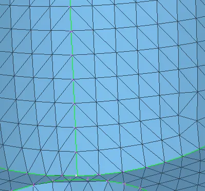
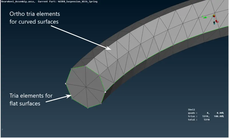
After executing complete shell meshing we proceed with volumetric meshing and for this we go V.MESH tab:
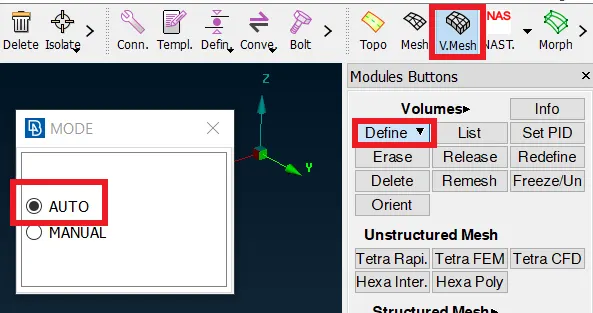
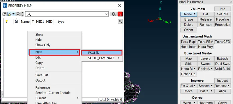
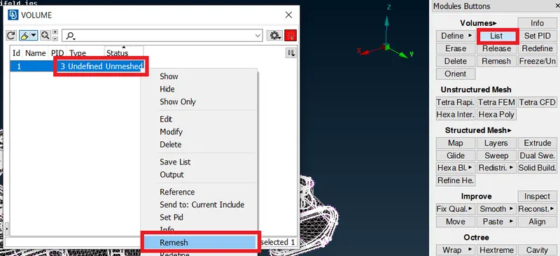
Solid mesh the components using REMESH option in LIST tab which can be accessed by right clicking on mentioned volume PID:
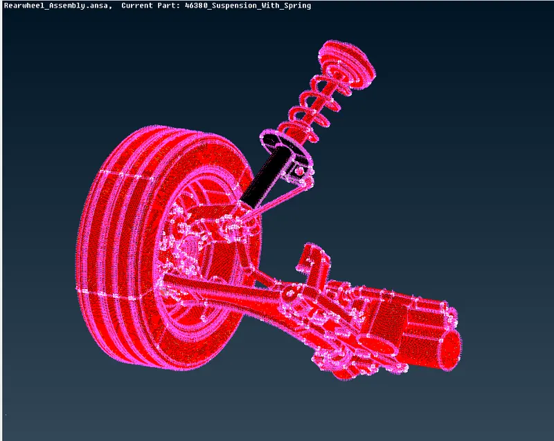
Use TETRA RAPID or TETRA FEM to solid mesh the model:
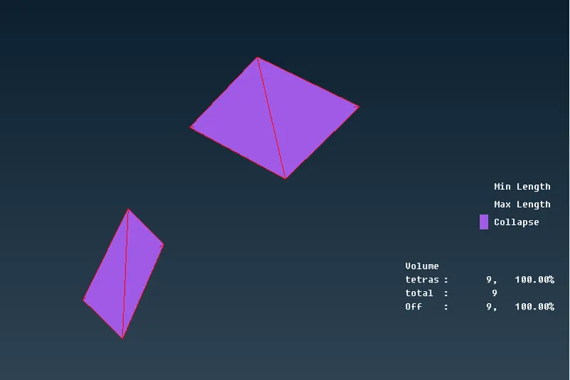
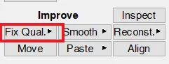
Remove any TET COLLAPSE quality issues using FIX QUALITY option in IMPROVE:
For any kinks use ALIGN option in MESH tab to align the nodes to required height or MV FREE option to move the grids, as Fxing quality can result in uneven. The surfaces must have smooth transitions, so eliminate any visible kinks.
What is Tet Collapse?
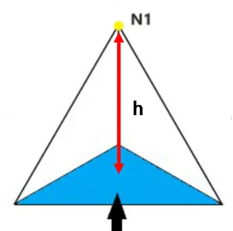
Tet collapse is one of the quality parameters, which will be checked while generating Tetrahedral elements. It can be calculated by measuring the distance of a node from the opposite face, then each of the four values will be divided by the Square root of the opposite face’s area. The minimum of four resulting values is then normalized by dividing it by 1.24.
Generally tet collapse can be calculated by the formula = Min of (h/√A) ÷ 1.24.
In that formula, “h” represents the Height, between the Node (N1) and the opposite face of the Triangle. “A” represents the Area of Opposite Face (area of the Triangle).
Meshing with Shell Elements:
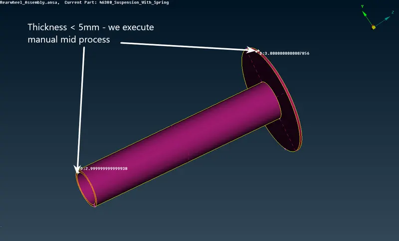
There were some parts in the rear-wheel assembly, which had thickness less than 5 mm. In such cases, meshing is performed on the shell-surface using manual mid extraction by Offest method
We extract the mid surface by using Offset tab in Faces section and select the following faces and provide required direction and offset distance in addition with Feature Angle command.
Setting PID and thickness assignment:
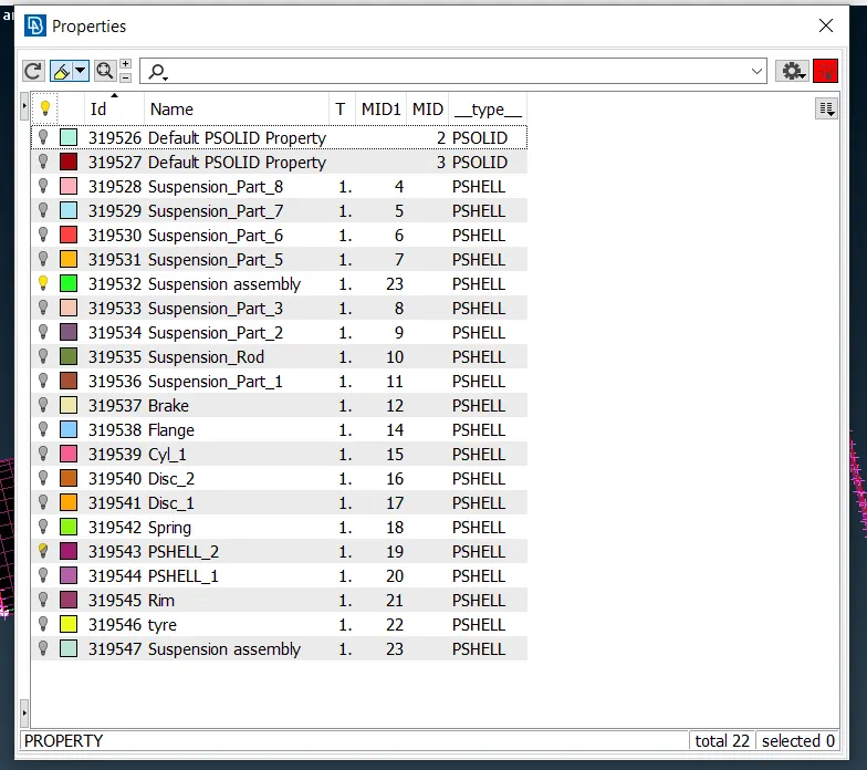
a) After extraction of middle surface of the given components we assign new PID and thickness to the parts by using Set PID tab under faces tab in TOPO mode.
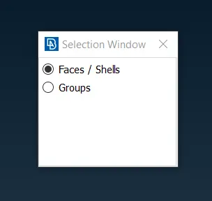
b) Select Faces and Shells option. c) Right click and select New → Pshell option. d) Assign PID and Thickness
Meshing of the component:
Now we proceed with meshing of the components:
a) Select MESH tab from upper right-hand corner
b) Press F11 to open quality tab and enter the given parameters
c) Open Mesh Parameter tab and enter target, minimum and maximum lengths.
d) Make user defined cuts using Cut tab as needed to get a good mesh flow.
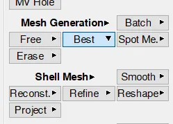
e) Use Best mesh tab under mesh generation tab and select faces to generate mesh.
Now, we will try to eliminate ‘Trias’ elements as much as possible in corners and opposite faced and we must completely eliminate any ‘Rotating Quads’ from the model to achieve better mesh flow.

Connections:
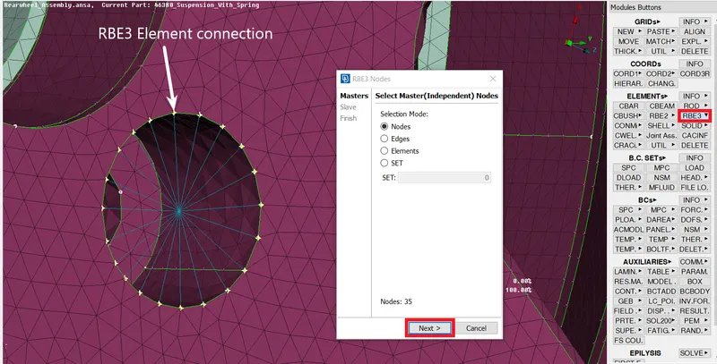
Part of pre-processing the assembly we need to assign connections after meshing. An assembly might be connected with threaded joints, seam or spot weld joints, sometimes bushing might present. So such a connection has to be deployed to represent the assembly as the integrated one but not the separated one. Bolted joints are generally represented using RBE2 or RBE3 elements and thus we will deploy connections s required for completing the assembly.
Multi Node RBE3:
NASTRAN >> RBE3 >> Loop Select >> Select the nodes of required perimeter
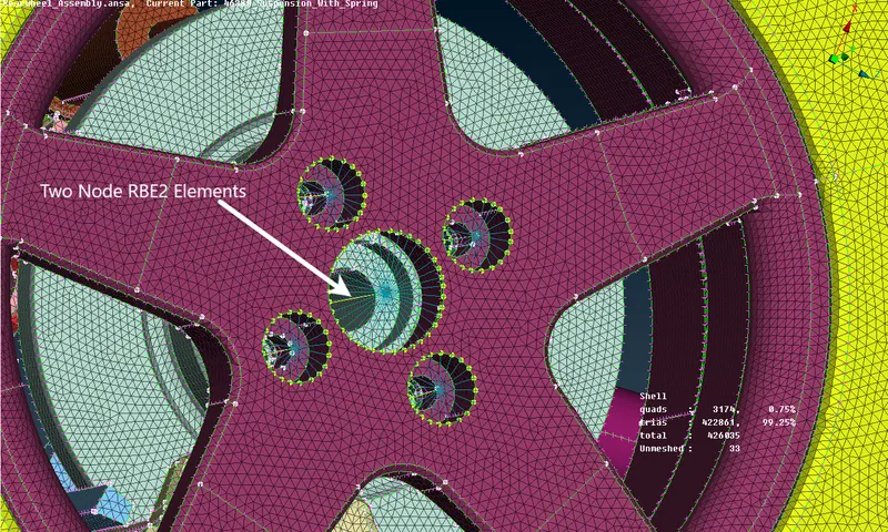
Two Node RBE2:
NASTRAN >> RBE2 >>> Two Nodes >> Select the master nodes which is needs to be connected
COMPLETED MODEL:
LEARNING OUTCOMES:
- What is solid meshing?
- Need for solid meshing?
- How to solid mesh a model?
- Types of solid meshes?
- Difference between Tria and Ortho tria elements
- Resolving quality issues: Tet Collapse
- Geometry clean up and error fixing.
- Performing topology operations.
- Creating mid-surface and PID assignment.
- Importance of mesh quality parameters.
- Model meshing against required quality criteria.
- Removing Tria elements and rotating quads using ‘Split, Swap, Smooth, Paste, Reconstruct and Reshape’ to achieve required mesh flow.
- What are connections?
- What are Type of connections?
- How to make connections in ANSA using NASTRAN deck?
- Application of appropriate connections as per requirement.
CONCLUSION:
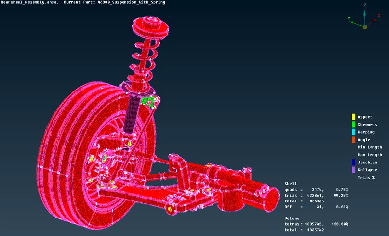
Provided model has been meshed under given quality criteria.
Model Link:
https://drive.google.com/file/d/1ucsCiImgoRIfUge5ZT0ibNJZRhgf_hFt/view?usp=sharing