Project 2
Aim:
Using MATLAB/simulink and the drive cycle from the attached excel sheet, find-
- The max heat generation of the battery
- The SOC of the battery at 2 *104second of the battery operation
| Time | Time Step | Battery Current |
| 00:00.4 | 0.1 | -0.9632 |
| 00:00.5 | 0.2 | -0.952 |
| 00:00.6 | 0.3 | -0.9072 |
| 00:00.7 | 0.4 | -0.9632 |
| 00:00.8 | 0.5 | -1.0304 |
| 00:00.9 | 0.6 | -0.9632 |
| 00:01.0 | 0.7 | -1.0304 |
| 00:01.1 | 0.8 | -1.008 |
| 00:01.2 | 0.9 | -0.9856 |
| 00:01.3 | 1 | -0.9632 |
| 00:01.4 | 1.1 | -0.9184 |
| 00:01.5 | 1.2 | -0.9296 |
| 00:01.6 | 1.3 | -0.9296 |
| 00:01.7 | 1.4 | -0.9296 |
| 00:01.8 | 1.5 | -0.9184 |
| 00:01.9 | 1.6 | -0.9408 |
| 00:02.0 | 1.7 | -0.896 |
| 00:02.1 | 1.8 | -0.9072 |
| 00:02.2 | 1.9 | -0.9072 |
| 00:02.3 | 2 | -0.9408 |
| 00:02.4 | 2.1 | -0.9296 |
| 00:02.5 | 2.2 | -0.9296 |
| 00:02.6 | 2.3 | -0.9968 |
| 00:02.7 | 2.4 | -0.9968 |
| 00:02.8 | 2.5 | -0.9408 |
| 00:02.9 | 2.6 | -0.9408 |
| Battery resistance | 2 milli ohm |
Consider the battery resistance is 0.5 mOhm, delta time is 0.1 and entropic factor is 2
1. The max heat generation of the battery
There are 2 heat sources for the battery heat generation
- Joules heat
- Entropy heat
Heat generated = Joules Heat + Entropy Heat
Joules Heat :
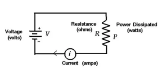
froms ohms law we know that
V = IR
when a current flowing through a resistance, there is a heat dissipated in the resistor. This heat dissipation is called Joule heating. Joule heating is also known as ohmic heating.
Power,
P = V*I = I*I*R = I^2*R
Heat,
H = ∫P.dt with the limits of time 0 to t
H = I^2*R*t
Joule heat,
H = I^2*R*t
where. p = Power
V = Voltage
I = Current
R = Resistance
H = Heat
t = Time
The heat Generated in the Reisitor is-
- Directly praportion to the square of the current flowing through it
- Directly praportion to the resistance
- Directly praportion to the time for which the current flows through it.
Entropy Heat:
The heat generation due to entropy change inside a battery occurs when electro chemical reactions are performed. The entropy heat is reversible heat resulting from change in open circuit voltage with respect to temperature at two Electrodes.
Given data
Battery resistance = 0.5 mOhm = 0.0005 Ohm
Maximun current = -0.896 A
Max current time = 1.7 sec
Entropic factor = 2
Total heat generation = Jouleheat + Entropy heat
The maximum heat generation in the battery pack
Max heat generation = Max Joule Heat + Entropy factor
Max Joule Heat = I^2 *R*t
Max Joule Heat = `-0.896^2*0.0005*1.7`
Max Joule Heat = `0.0006823936J` `
Max heat generation = 0.0006823936 + 2 = 2.0006823936 Jouls
The Max heat generation is 2.0006823936 Jouls
2. The SOC of the battery at 2 *104second of the battery operation:
The SoC refers to the State of Charge of the battery, which is the capacity percent left in the battery which can be used. It a very improtent thing which teles about the battery status which helps in using the battery in a proper manner.
The SoC can be measued in different ways. Some of them are listed below
- Voltage Translation Method (VT)
- Coulamb counting method (CC)
- Combination of VT and CC
The VT and CC has its own advantages ad disadvantages so to get accurate value we have to use the Combination of VT and CC.
Voltage Translation Method (VT):
It is measued by Open Circut Voltge of the battery and compared it with the Data sheet of the battery and SoC is estimated. It cannot used while the battery is in operation.
Coulamb counting method (CC):
It is calculated by the formula
SoC = total charge input / Max capacity of the battery
Total charge input = charge current * time (H)
Or
Z(t) = Z(0) - 1/Cn ∫ Ni*i(t) dt with thw limits of 0 to t
where, Cn = Battery Nominal Capacity
Z(t) = State of charge
i(t) = Instantansous cell current
t = time
Ni = coulomb efficiency
Z(0) = initial state of charge
+ for discharging
- for charging
Due to Faid in the battery capacity over the time it shows error
Combination of VT and CC:
To avoid the calculation of SoC both the Voltage Translation Method (VT) and Coulamb counting method (CC) are used combinedly.
Simulation:
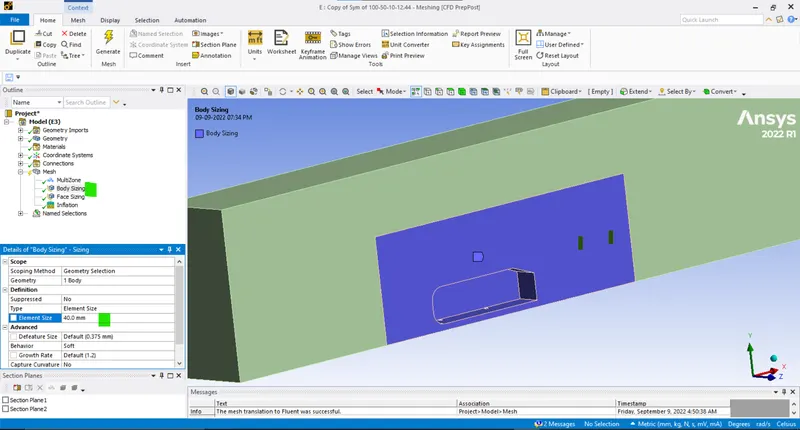
The Battery specifications are taken as shown below
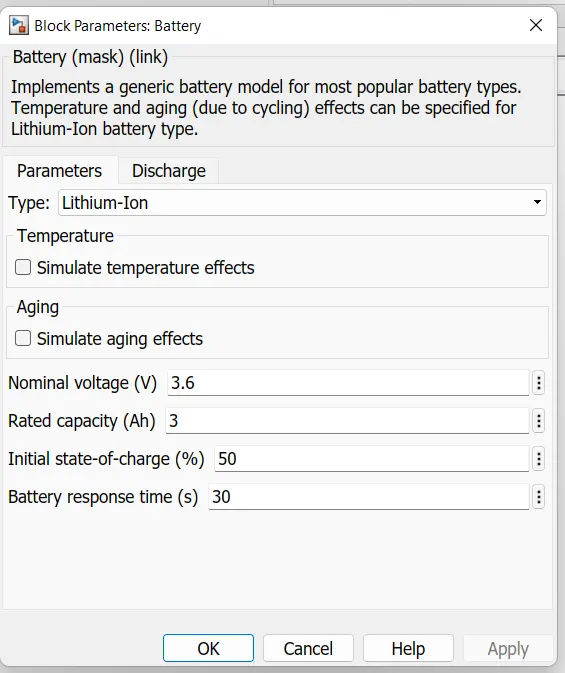
Charge and Discharge command or Siganal to run the Constant Currnet source, so that the current will flow in and out according to the signal. + signal to chagrge and - for discharge. The total time for the run is taken as 2*104 = 208 sec
The Current signal is taken with the time of 0 to 208 sec with 1 sec step as
22 -22 -7 -6 39 -27 -42 76 31 14 53 -29 75 46 -12 33 79 -50 -41 3 41 -25 2 4 -18 -24 -42 55 22 80 3 -1 69 93 1 46 89 50 -23 -49 -43 21 -2 83 -14 24 -13 -50 21 87 -22 15 32 -10 96 13 -22 5 -46 76 59 43 -42 79 78 65 -23 -47 -36 -44 -1 72 21 28 62 79 13 100 85 20 74 17 41 32 12 -18 78 -31 -1 -3 -28 -32 -26 -18 81 -16 -25 76 12 61 -16 0 96 97 71 95 -6 -23 -39 -50 -22 -48 65 -13 5 -7 -16 -13 37 63 -45 -47 -28 -1 46 27 -17 -49 97 56 1 -25 -11 -47 89 24 79 32 66 56 32 30 -18 -22 86 58 2 -18 -39 -25 42 10 52 21 57 22 -36 18 44 -45 86 30 52 78 -16 -14 73 -46 -35 39 47 -19 84 -33 -45 73 -10 37 36 51 67 99 5 87 67 -34 8 -7 72 16 36 -45 0 -25 57 -37 53 65 -9 -29 -43 44 51 -11 55 -6 72 74 58
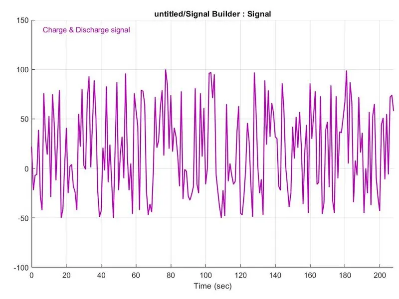
Graph:
Result and Conclusion:
1. The max heat generation of the battery
The Max heat generated in which the current flowing in and out i.e., charge and discharge due to internal resistance and chemical reaction during charging and discharging of the battery the heat is generates of 2.0006823936 Jouls
2. The SOC of the battery at 2 *104second of the battery operation:
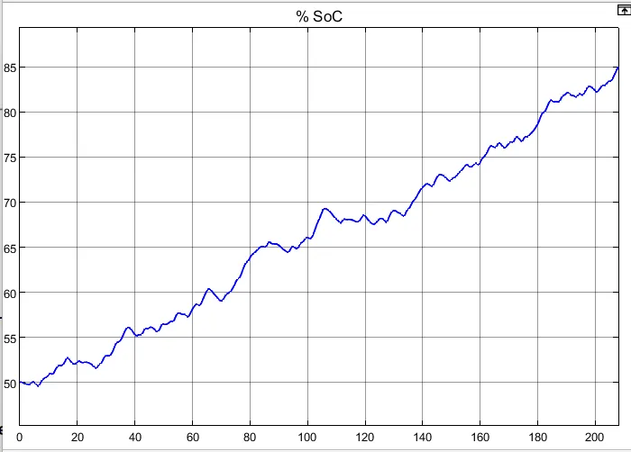
Initially the battery SoC is taken as 50% so it started and according to the current signal i.e., charge and discharge, if the charhing happens the battery SoC is increasing and when it is discharging SoC is decreasing.