Project 2
1. Design a Warehouse Building located in Chennai using STAAD Pro Connect Edition. The specification must be as follows:
|
Width |
30m |
|
Length |
50m |
|
Eave Height |
9m |
|
Bay spacing |
6m |
|
Soil type |
Medium |
|
Safe Bearing Capacity |
200 kN/m2 |
|
Roof slope |
1 in 12 |
Assume suitable sections for structural elements. Follow IS800:2007, IS1893 and IS 875
- Prepare a Design Basis Report for the project
- Create structural model using STAAD Pro Connect Edition
- Prepare DL, LL, WL and EQL load calculations as per IS 875 standards
- Design using MS – Excel
- Steel column
- Rafter
- Base plate
- Pedestal
- Z- purlin
- Design Foundations using STAAD Foundation.
- Attach necessary sketches and drawings wherever required.
- All stipulations, assumptions and design parameter must adhere to Indian Standards.
Step 1: Model is prepared in STAAD Pro.
Step 2: Section properties and Materials are applied to all the members.
Step 3: Releases and specifications are applied.
Step 4: Support conditions are applied.
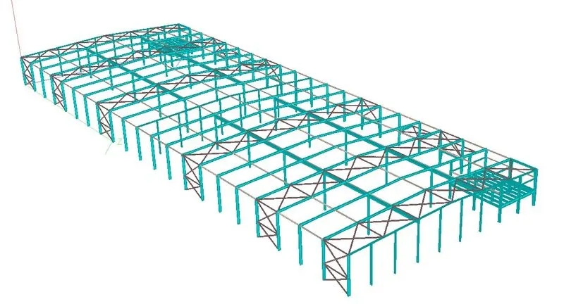
3D Rendering is as follows
Step 5: Loading are calculated and Design Parameters are applied.
Calculation of Design Loads on PEB Structure – Project 2
- Dead Load
- Dead Load on Rafter
- Weight of Roof Sheet = 5 Kg/m2
- Weight of Purlin and sag rods = 5 Kg/m2
- Additional weight = 5 Kg/m2
Total weight of rafter = 15 Kg/m2
Dead load on rafter = 15 x 10 x 8 = 1200 N/m = 1.2 kN/m
- Dead Load on Purlin = 10 x 10 x 8 = 800 N/m = 0.8 kN/m
- Mezz Slab self-weight (150 mm thk slab) = 0.15 x 25 kN/m3 = 3.75 kN/m2
- Floor Finishes and additional load on Mezz Floor = (150 + 500) kg/m2 = 0.65 kN/m2
- Weight of 230mm thick brick wall (4-meter height) on Mezz floor = 20 kN/m3 x 0.23 x 4 = 18.4 kN/m
- Live Load
- Live Load on Roof and canopy = 57 kg/m2 x 10 x 8 = 4.56 kN/m
- Live Load on Mezz Floor = 400 kg/m2 = 4 kN/m2
- Collateral Load
- Collateral Load on Roof
- Load of Electrical fittings = 0.1 kN/m2
- Load of Sprinklers = 0.03 kN/m2
- Load of rockwool Insulation and bubble wrap insulation = 0.15 kN/m2
- Load of Solar Panels = 0.15 kN/m2
- Load of Ceiling = 0.1 kN/m2
Total Collateral load on Roof = 0.53 x 8 = 4.24 kN/m
- Collateral Load on Mezz Floor (due to false ceiling & electrical fittings)
= 0.2 x 8 = 1.6 kN/m
- Collateral Load on column due to Bracket Beam
Load due to service line supported on the beam spanning 8 m width= 150 kg/m x 8 x 10 = 12 kN
Moment acting on column due to service line = 12 x 0.75 = 9 kNm
- Collateral Load on Jack Beam due to service line= 2.5 kN/m
- Collateral Load on Mezz False Ceiling = 3.2 kN/m
- Wind Load
Basic wind speed = 50 m/s for chennai
K1 - 1.00
K2 - 1.05 (Terrain Catogory-1. Building height at eaves = 10.50 m)
K3 - 1.00
K4 - 1.00 (For other structures)
Coefficient of cyclonic wind may be taken as 1,
Kd -0.9
Ka (Rafter) - 0.8 or as per tributary area.
Ka (Column) - 0.8245 or as per tributary area.
Ka (Purlin) - 0.9721 or as per tributary area.
Ka (Side Runner) - 0.978 or as per tributary area
Kc -0.9
Design wind pressure = pd = kd x ka x kc x 0.6 x (Vb x k1 x k2 x k3 x k4)2 = 0.652 kN/m2
But should not be less than 0.7 Pz = 0.7 x 1.006 = 0.704 kN/m2
Cpe - As per table 5 & 6 of IS: 875 (Part 3) – 2015
h/w = 10/60 = 0.6
L/w = 170/60 = 2.83
Cpe On wall:
|
Direction |
A |
B |
C |
D |
|
0 deg. |
0.7 |
-0.25 |
-0.6 |
-0.6 |
|
90 deg. |
-0.5 |
-0.5 |
0.7 |
-0.1 |
Cpe On Roof:
Roof angle = 2.86
|
Direction |
EF |
GH |
EG |
FH |
|
0 deg. |
-0.86 |
-0.4 |
||
|
90 deg. |
-0.8 |
-0.4 |
Cpi = 0.2
Wind Load on Columns = (Cpe – Cpi) x A x Pd
Wind about X Direction + Cpi = (0.7 – 0.2) x 8 x 0.704 = 2.816 kN/m on Wall A
Wind about X Direction + Cpi = (-0.25 – 0.2) x 8 x 0.704 = -2.534 kN/m on Wall B
Wind about X Direction + Cpi = (-0.6 – 0.2) x 6.75 x 0.704 = -3.802 kN/m on Wall C & D
Wind about X Direction - Cpi = (0.7 + 0.2) x 8 x 0.704 = 5.069 kN/m on Wall A
Wind about X Direction - Cpi = (-0.25 + 0.2) x 8 x 0.704 = -0.282 kN/m on Wall B
Wind about X Direction - Cpi = (-0.6 + 0.2) x 6.75 x 0.704 = -1.9 kN/m on Wall C & D
Wind about Z Direction + Cpi = (-0.5 – 0.2) x 8 x 0.704 = -3.942 kN/m on Wall A
Wind about Z Direction + Cpi = (-0.5 – 0.2) x 8 x 0.704 = -3.942 kN/m on Wall B
Wind about Z Direction + Cpi = (0.7 – 0.2) x 6.75 x 0.704 = 2.376 kN/m on Wall C
Wind about Z Direction + Cpi = (-0.1 – 0.2) x 6.75 x 0.704 = -1.425 kN/m on Wall D
Wind about Z Direction - Cpi = (-0.5 + 0.2) x 8 x 0.704 = -1.689 kN/m on Wall A
Wind about Z Direction - Cpi = (-0.5 + 0.2) x 8 x 0.704 = -1.689 kN/m on Wall B
Wind about Z Direction - Cpi = (0.7 + 0.2) x 6.75 x 0.704 = 4.276 kN/m on Wall C
Wind about Z Direction - Cpi = (-0.1 + 0.2) x 6.75 x 0.704 = 0.475 kN/m on Wall D
Wind Load on Rafters = (Cpe – Cpi) x A x Pd
Wind about X Direction + Cpi = (-0.86 – 0.2) x 8 x 0.704 = -5.970 kN/m on Side A Rafter
Wind about X Direction + Cpi = (-0.4 – 0.2) x 8 x 0.704 = -3.378 kN/m on Side B Rafter
Wind about X Direction - Cpi = (-0.86 + 0.2) x 8 x 0.704 = -3.716 kN/m on Side A Rafter
Wind about X Direction - Cpi = (-0.4 + 0.2) x 8 x 0.704 = -1.125 kN/m on Side B Rafter
Wind about Z Direction + Cpi = (-0.8 - 0.2) x 6.75 x 0.704 = -4.752 kN/m Side C Rafter
Wind about Z Direction + Cpi = (-0.4 - 0.2) x 6.75 x 0.704 = -2.851 kN/m Side D Rafter
Wind about Z Direction - Cpi = (-0.8 + 0.2) x 6.75 x 0.704 = - 2.851kN/m Side C Rafter
Wind about Z Direction - Cpi = (-0.4 + 0.2) x 6.75 x 0.704 = -0.950 kN/m Side D Rafter
Wind Load on Canopy
Cp - As per table 8 of IS: 875 (Part 3) – 2015
Roof Angle 2.86 deg.
Cp -ve = 1.08
Cp +ve = 0.35
Wind Load on Canopy (Upward) = 1.08 x 8 x 0.704 = 6.082 kN/m
Wind Load on Canopy (Downward) = 0.35 x 8 x 0.704 = 1.971 kN/m
- Seismic Load
As per IS: 1893 - 2016
Seismic zone - III - Z = 0.16
Rf - 4.0
I - 1.0
SS - 3.0
25% of Live Load on roof considered for calculation of seismic forces.
100% of collateral load on roof considered for calculation of seismic forces.
50% of (Live load + Collateral load) on mezzanine floor considered for calculation of seismic forces.
100% of Dead load considered for calculation of seismic forces.
Design Parameters:
- IS 800 LSD
- FYLD = 345000 for Portal frame and Mezz Beams
- FYLD = 250000 for Bracings
- BEAM = -1
- STP = 2 for welded sections
- MAIN = 250 for tie beam
- Ly = Lx = 1.5m for Rafter
- Ly = Lx = 3.25m for Columns
- Ly = Lx = 4.4m for columns supporting canopy
- Lz = 11m for Internal columns
- Ly = Lx = 0.5m for Mezz floor beams
- Lz = 6.75m for Mezz Floor beams
- Ly = 1.7m for Canopy Beam
- RATIO = 1
- STEEL TAKE OFF
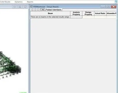
Results of the analysis is as follows which shows are members are passing and no member property has failed.
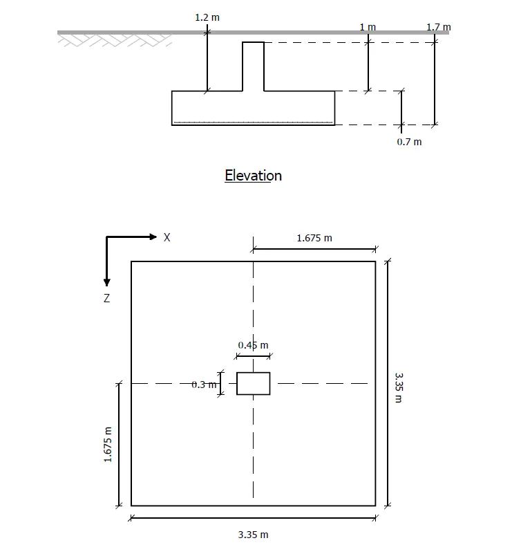
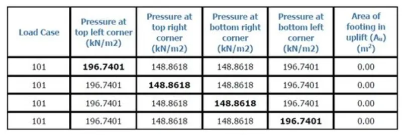
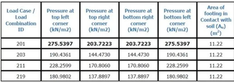
Foundation Design:
2. Design a simply supported gantry girder to carry electric overhead travelling crane
Given:
Span of gantry girder = 7 m
Span of crane girder = 9 m
Crane capacity = 250 kN
Self-weight of trolley, hook, electric motor etc. = 40 kN
Self-weight of crane girder excluding trolley = 100 kN
Minimum hook approach = 1.0 m
Distance between wheels = 3 m
Self-weight of rails = 0.2 kN/m