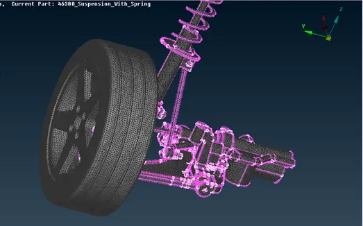
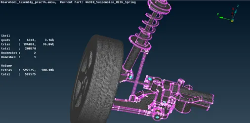
Project 2
Objective:-
To mesh the given component using the various tools we have with us. Check for the geometrical errors and mesh with the given element Quality criteria.
Tools used:-
- Insert-hotpoints
- Project hotpoints
- Delete hotpoints
- Release cons
- Project cons
- Cut faces
- Delete faces
- New faces
- Set PID
- Project cut
- Offset faces
- Auxilliaries fine
- Perimeters length
- Perimeters number
- Cut macros
- Grids move
- Best mesh generation
- Spot-mesh mesh generation
- Re-construction shell mesh
- Smooth shell mesh
- Elements swap
- Elements delete
- Volumes-define
- Volumes-list
- Improve-fix quality
- Tetra FEM unstructured mesh
- Elements –RBE2(Nastran deck)
- Bolt command
Procedure followed:-
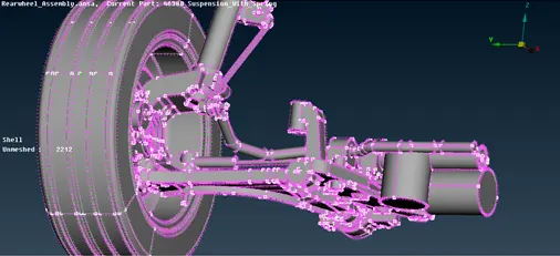
Export the iges file, and check for any errors, like bad cons,missing surfaces ,etc.
Geometry check is an important part of the processing of the component before meshing. so performing geometry check for the available component,
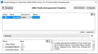
Post geometry check, we will be starting with individual meshing of the components.
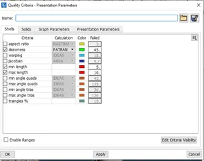
To start with I am starting with wheel and rim component. Quality parameter for wheel and rim is to be set for further processing.
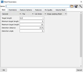
Mesh parameter for wheel and rim has been set.
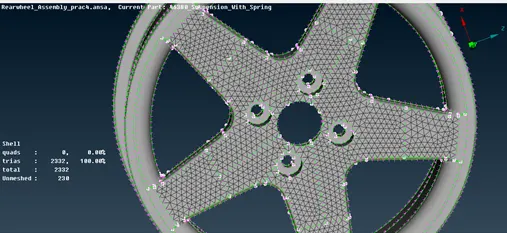
Individually meshing the parts of rim and tyre according to requirement of tria and ortho-tria elements.
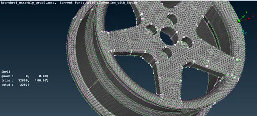
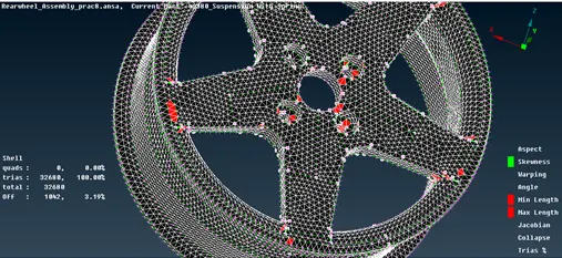
Tetra meshing the component we have performed surface trai. First of all we have to define the volumes and then by going to list command and then remeshing the component we can attain tetra-mesh for Wheel and rim.
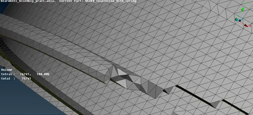
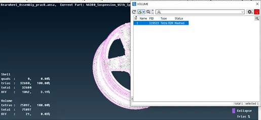
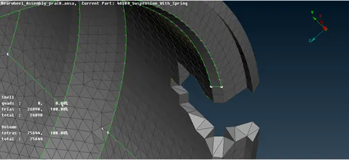
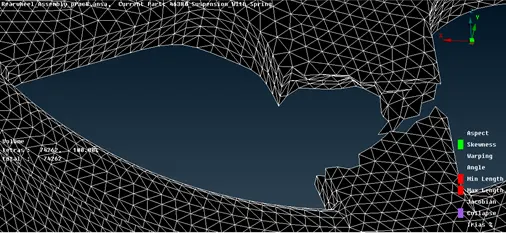
The rim tetra meshed is without any tet-collapse.
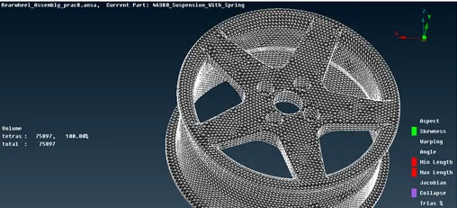
tyre:
After rim we will be meshing the tyre which has the same quality criteria as that of rim.
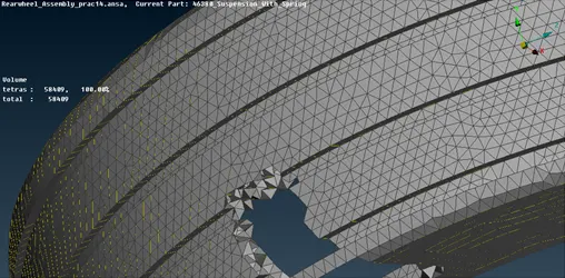
Moving in to another component steering box tria mesh with different quality parameters:-
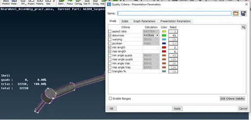
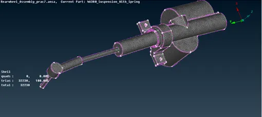
Post reconstruction negligible quality error,
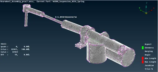
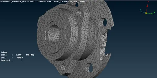
The steering is then tetra meshed for better meshing,
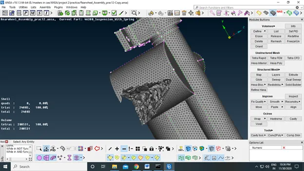
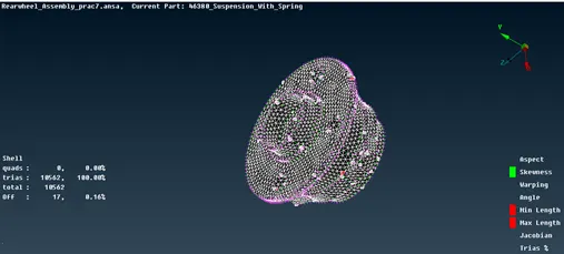
After steering box, Hub part is to be tria meshed because of its non-uniform structure. And before meshing the hub it is to cleaned for better mesh quality.
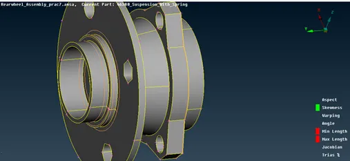
Meshing surface with tria element,
Tetra meshed hub
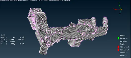
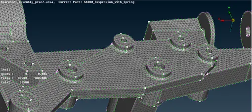
Post hub, Sub-frame part has to be meshed with tria element.
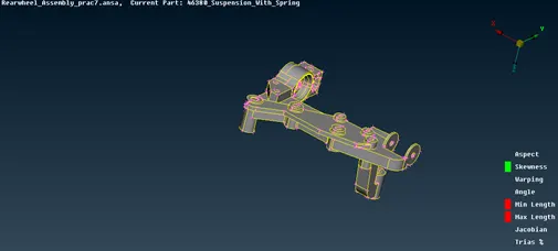
Meshed
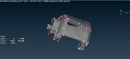
Proceeding towards next part i.e.Caliper assy
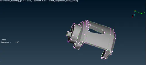
Meshed
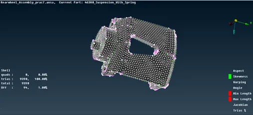
Knuckle:
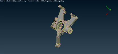
With errors at first spotmesh, clearing it using reconstruction option.
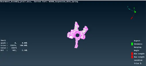
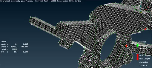
After reconstruction the mesh flow is slight proper comparatively
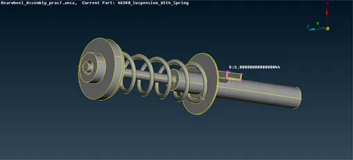
Shock absorber
Meshed
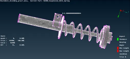
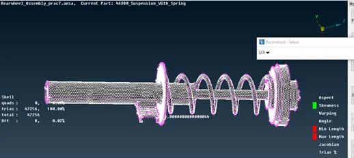
Reconstructed shock absorber for better mesh quality,
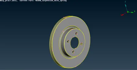
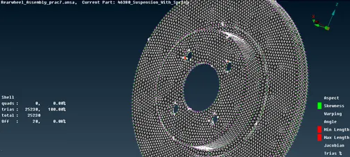
Brakes disc is to be meshed after the shock absorber,
Meshed with trias
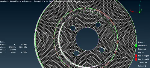
Reconstruction and elemental cleanup
Stabilizer bar:-
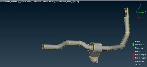
Meshed
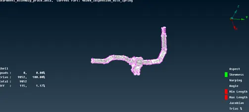
cLeanup
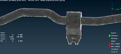
Link rod
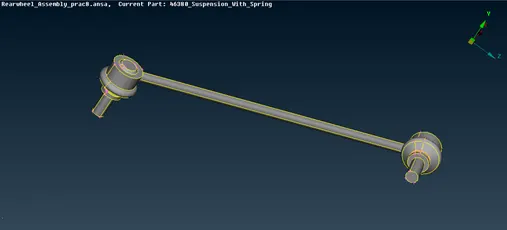
Meshed link rod
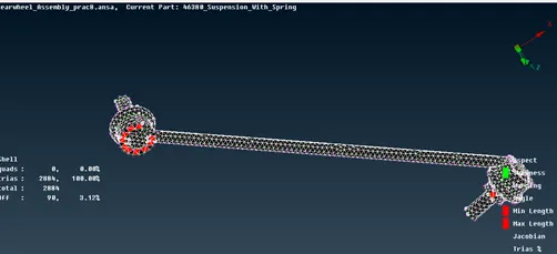
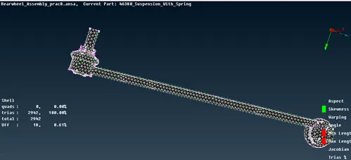
Cleanup of link rod for better mesh flow is done,
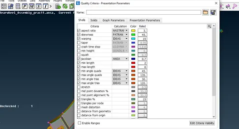
Setting parameter for only mid-surface component i.e. lower arm is the only component which can be mid-surfaced.
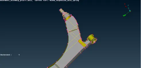
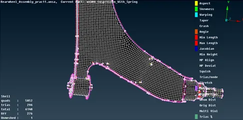
Meshed lower arm component is attached here.
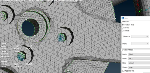
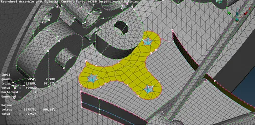
After all the meshing of the parts we will proceed towards the connections wherever required for better connectibility. Bolt connection has been deployed wherever necessary.
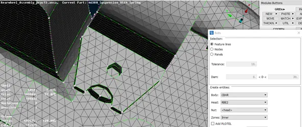
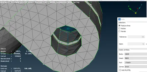
Bolt connection for wheel nut
Bolt connections for lower arm
Conclusion:-
In the above project the following tasks were performed:-
- Mid-surface of the components
- Tria-meshing to the surface
- Volume meshing or Tetra meshing of the component having random thickness.
- Connections were made in between the required components.
The component obtained after all the criterion done is attached below.