Project 2 - 2D meshing on the instrumental Panel
OBECTIVE
The objective of this assignment is to mesh the given CAD model of a car dashboard with a target element length of 4 following the given quality criteria. Since the model is plastic proper generation of midsurface and assigning of correct thickness to each surface is also required.
|
Sl no |
Quality criteria | Value |
| 1 | Target /average length | 4 |
| 2 | Minimum length | 2 |
| 3 | Maximum length | 6 |
| 4 | Aspect | 3 |
| 5 | Warpage | 15 |
| 6 | Skewness | 45 |
| 7 | Jacobian | 0.7 |
| 8 | Minimum quad angle | 45 |
| 9 | Maximum quad angle | 135 |
| 10 | Minimum tria angle | 30 |
| 11 | Maximum tria angle | 120 |
| 12 | Tria percentage | 15 |
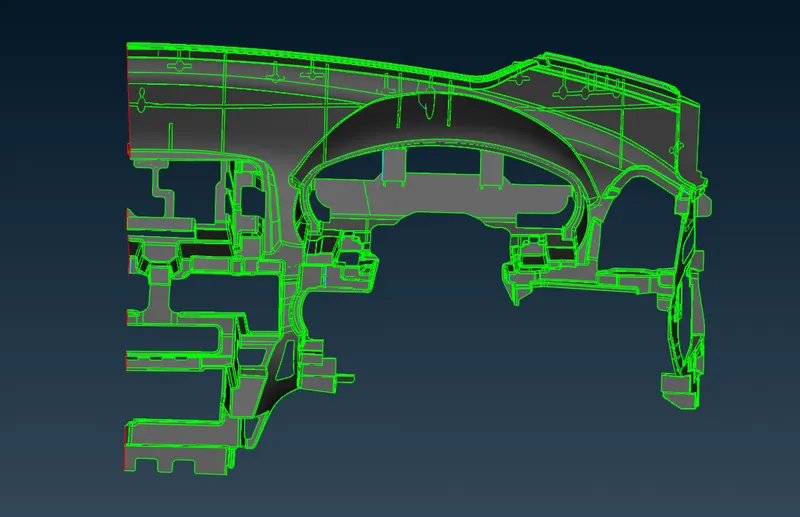
The cad model image of the given sample is shown below.
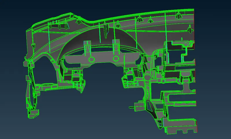
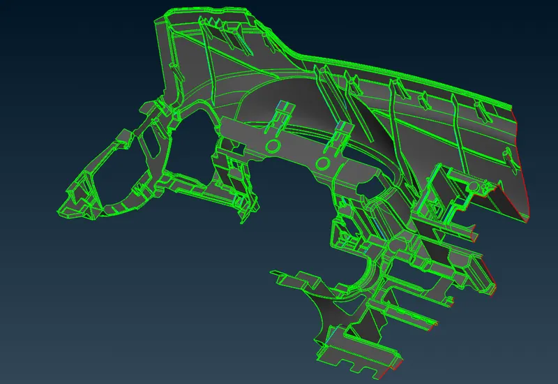
PROCEDURE
The model is imported onto ansa and then topology operation is performed. Then it is checked for any geometry errors using the checks>geometry tool. Geometry errors was fixed using checks>geometry>fix option and various other tools such as faces>delete , faces> new>fitted , faces>modify, cons>release etc.. Since the component was large the component was divided into different parts for easier workflow. Since the component was very complex and not fully closed automidsurface was not a great option so manual midsurfacing was done using faces> offset option. The base midsurface was generated first and then midsurface for ribs were generated. The midsurface for ribs were generated using faces>middle option and then was extended into the base midsurface using faces> extend> target option. Some of the other tools that were used for midsurface generation and cleanup include faces>intersect , cons>paste, cons >break , faces>cut ,faces>topo ,faces>dach , curves> create ,curves >cons 2 curve ,points> on cog etc..
After midsurface generation the mesh parameters and mesh quality criteria is then assigned. Since our target element length is 4 , shell element length is set to 4 using length option (mesh>perimeters>length). Since the component was very large it was meshed using the batchmesh option (tools>batchmesh). The batchmesh generated sufficient quality mesh but had problematic areas especially around sharp curves and areas along triple cons. These errors were corrected manually using various tools such as grids >move ,grids> origin ,grids>paste ,mesh generatrion>best ,shell mesh>reconstruct ,shell mesh >smooth ,elements>split ,elements>swap ,elements>new ,elements>join ,elements >delete ,macros >release ,macros > cut ,macros >join ,macros >edge2perimeter etc..
Some of the common criterias that were followed to obtain a geat quality mesh were
- The tria elements should never be opposite to each other
- No tria elements should be connected back to back
- No tria elements should be on the edge of the geometry
- No tria elements should be on the edge of the geometry
- No tria elements should be near the holes.
- No tria elements should be on the feature and the fillets
- There should be less tria concentration.
Most quality issues relating to tria were managed using elements>split, elements>swap, elements>join, grids>paste ,shell mesh>smooth options.Warpage issues were common occourence in areas where there was a sharp turn in geometry, these were most often fixed by using grids>move tool . Since the component contained various portions of different thickness , thickness was assigned accordingly.
RESULTS
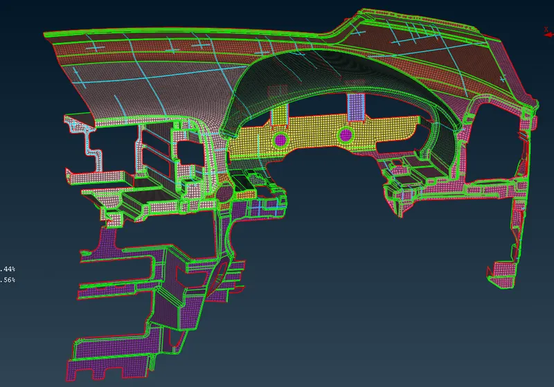
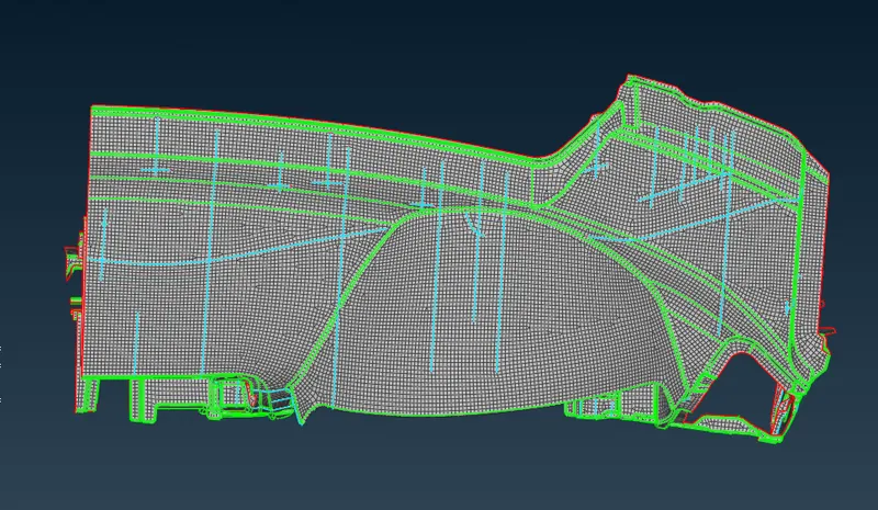
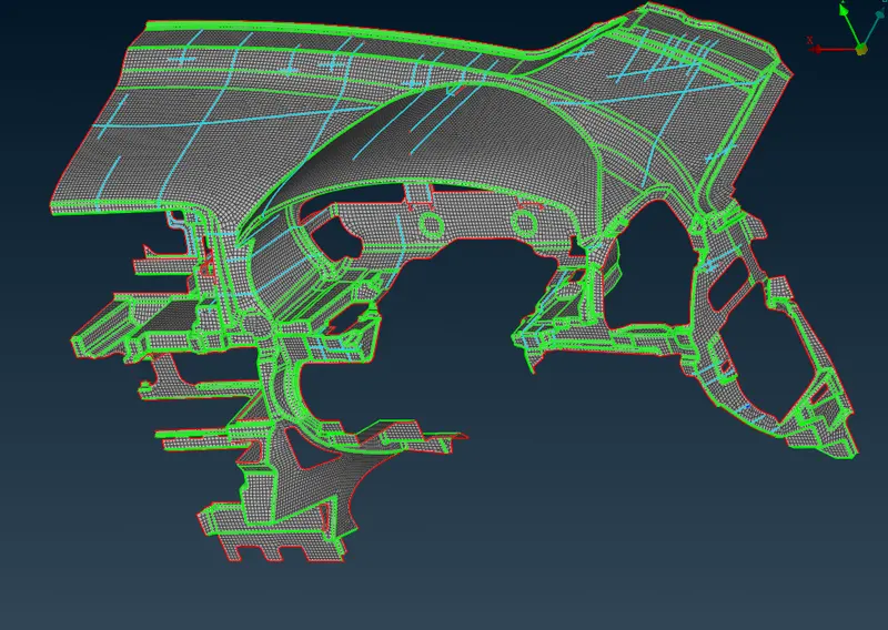
The component was successfully meshed satisfying all the quality criterias .The final meshed model is shown below.