Project 2 - 2D meshing on the instrumental Panel
Project - 2
2D MESHING ON THE INSTRUMENTAL PANEL
Report
Aim
Prepare post-processing for Floor panel by eliminating geometrical errors, using ANSA pre-processing software.
Objective
For the given sheet metal CAD model of the Instrumental panel of the vehicle,
- to check for geometrical errors
- take the mid surface.
- mesh the Surfaces with the given 2D element Quality criteria.
- assign thickness.
Abstract
In this project, the instrument panel of the car dashboard is taken for the pre-processing stage of CAE. The pre-processing of this model is done using BETA-CAE-ANSA software. The mid-surface extraction and shell meshing are mainly demonstrated here in this project. Also, the good practices to be followed during shell meshing are discussed here.
Methodology:
The methodology for the given element is as follows:
- Import geometry.
- Perform a Geometrical cleanup.
- Quality criteria and parameters.
- Generate mid-mesh by casting method.
- Resolve all the errors.
- Assign Thickness to the Components
- Result
- Learning outcome.
- Final image.
Introduction:
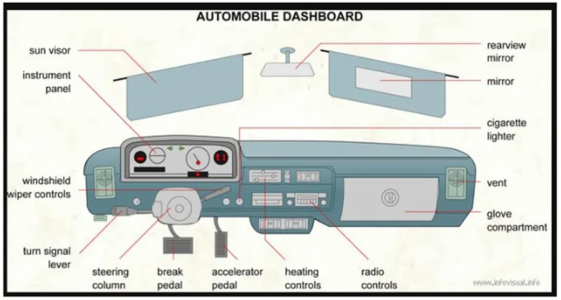
A dashboard (instrument panel (IP), or fascia) is a control panel usually located directly ahead of a vehicle's driver, displaying instrumentation and controls for the vehicle's operation.
The instrument panel, as the largest inner trim part which is directly shown to the passenger, have not only beauty and function requirements but also NVH and safety request. The vibration and the noise on the dashboard can be directly felt by the passenger.
These days car dashboards may include so many indicators like a speedometer, tachometer, odometer, fuel gauge, turn indicators, gearshift position indicator, seat belt warning light, and engine-malfunction lights. Other features may include a gauge for alternator voltage, indicators for low fuel, low oil pressure, low tire pressure and faults in the airbag (SRS) systems, lighting controls, safety systems, and entertainment.
The dashboard can be made from metal in the simplest and cheapest way. This could be the same base metal as the car, which is steel or Aluminium. The more expensive luxury Cars are made of exotic wood with a highly polished finish. Usually, the top layer on old cars is PVC. More recently, dashboard coverings have been made of PVC blended with something called ABS. ABS is an acronym for a block copolymer made of acrylamide, butadiene, and styrene.
Thus, FEA analysis of the instrument panel plays a very important role in the NVH character of the whole vehicle.
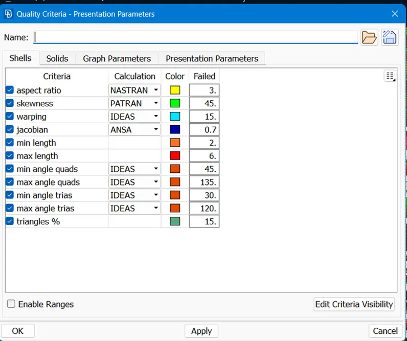
Quality criteria
|
S.No |
Quality Criteria |
Value |
|
1 |
Target/Average length |
4 |
|
2 |
Minimum Length |
2 |
|
3 |
Maximum Length |
6 |
|
4 |
Aspect |
3 |
|
5 |
Warpage |
15 |
|
6 |
Skewness |
45 |
|
7 |
Jacobian |
0.7 |
|
8 |
Minimum Quad Angle |
45 |
|
9 |
Maximum Quad Angle |
135 |
|
10 |
Minimum Tria Angle |
30 |
|
11 |
Maximum Tria Angle |
120 |
|
10 |
Tria Percentage |
15 |
Procedure
- Import geometry:-
First of all, the model was created by a design engineer based on requirements but that engineer is not understand about this model is good or bad then ANSA software is required the check the quality criteria.
First of all import a file of the model in ANSA software.
FILE > OPEN > (MODEL)
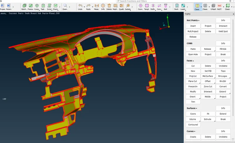
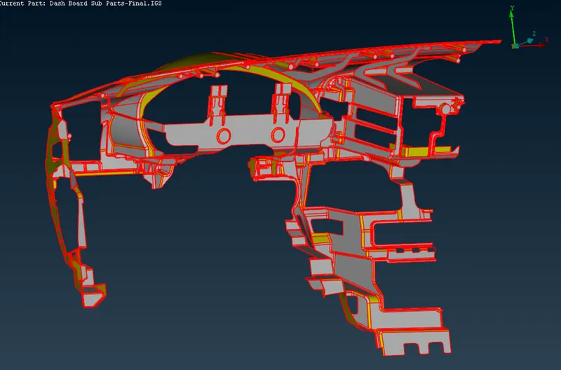
We can see there are many single cons and faces are not stitched properly.
2. Perform TOPO on it, as the model is too distorted after importing from different software.
Classic TOPO > Faces > TOPO
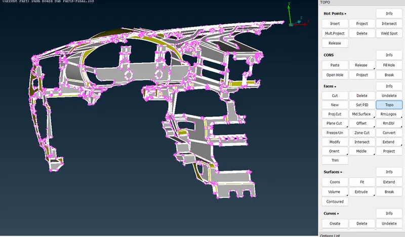 3. Geometry Check and execute
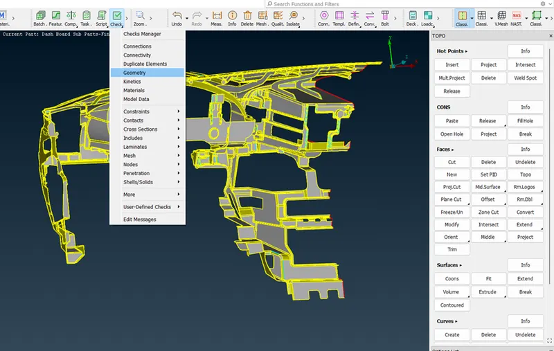
4. There are almost 791 errors. Select all the errors and perform
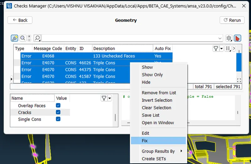
5. Now we can see some of the errors have been fixed by ANSA. The errors have been reduced to 208.
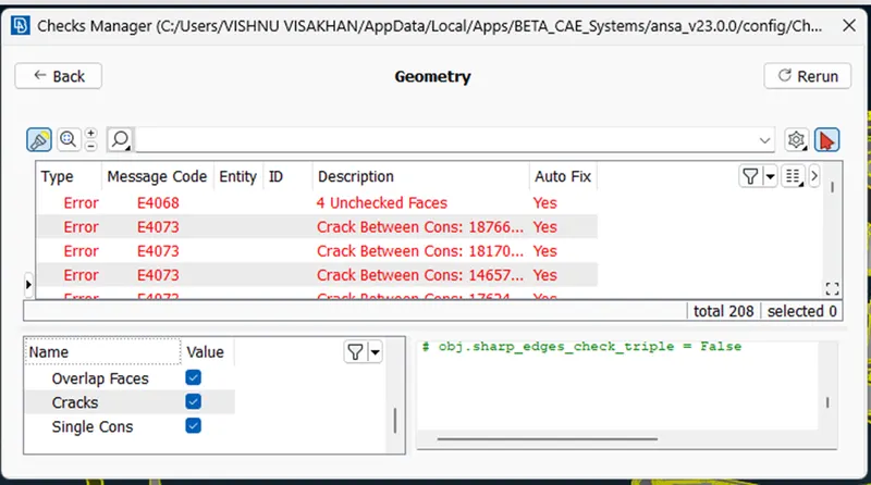
6. Select the remaining errors and click show all.
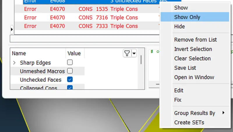
7. Now go to individual errors and fix them.
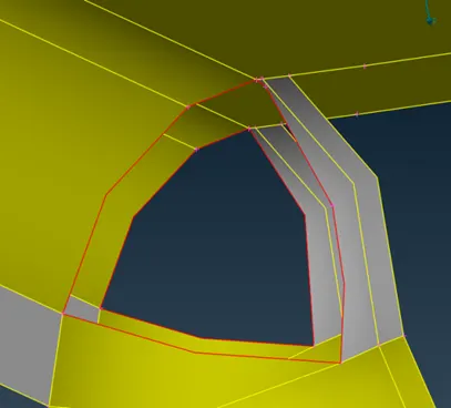
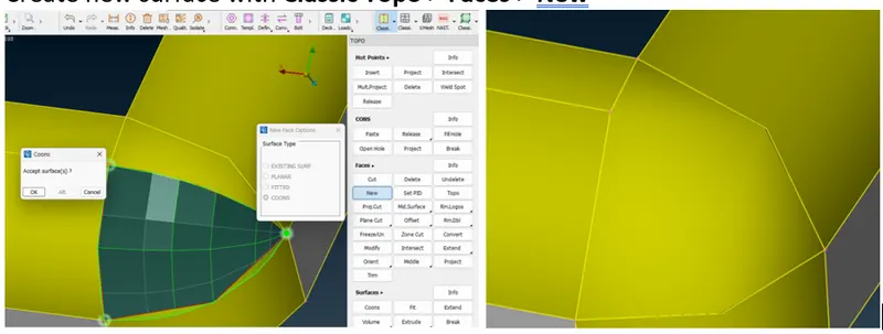
8. Improper surface
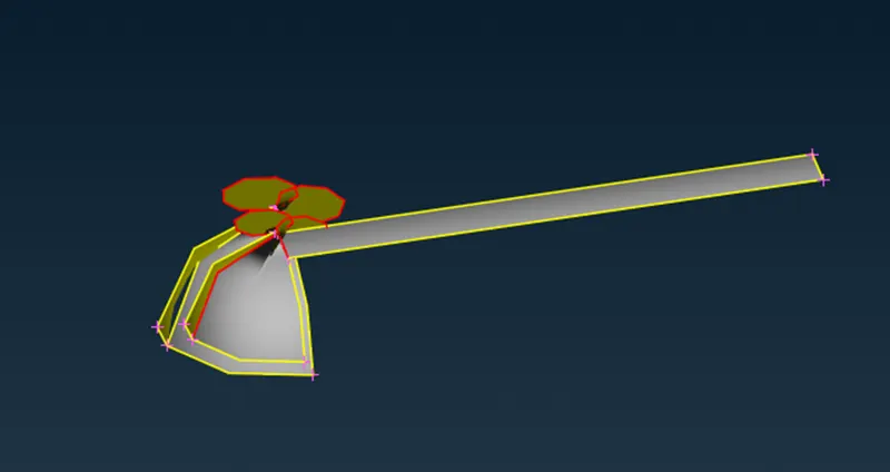
Select Neighb 1st level to see the nearby surfaces.
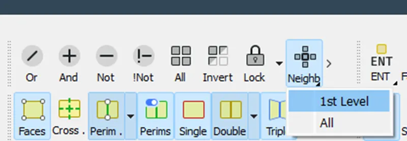
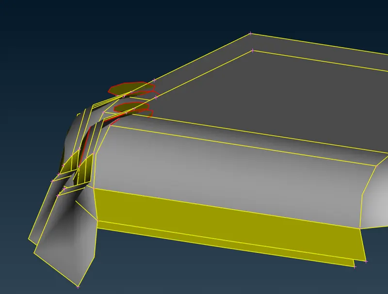
Delete the improper surface, Classic Topo > Faces > Delete\
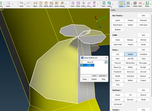
Create new surface with Classic Topo > Faces > New
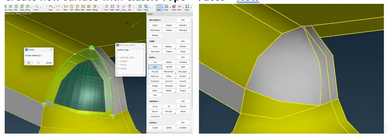
9. Go for other errors also and fix them.
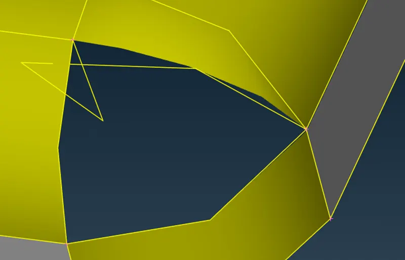
Delete the improper surface Classic Topo > Faces > Delete
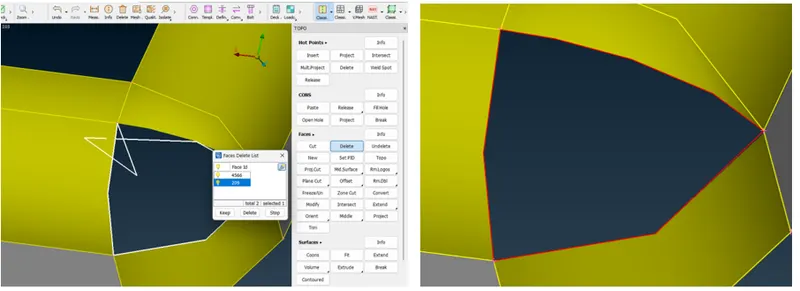
Create a new surface with Classic Topo > Faces > New
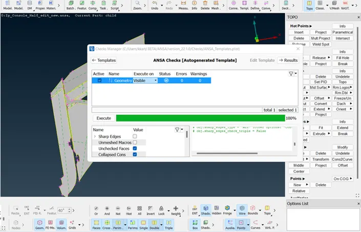
10. Clean the geometry using the checks manager. Enable unchecked faces, collapsed cons, triple cons, needle faces, overlapped faces, cracks, and single cons. Clear all these issues until no error is found. One can use fix option in ANSA to clear all the errors automatically. However, sometimes manual intervention is required for fixing some errors.
11. Quality criteria and parameters:
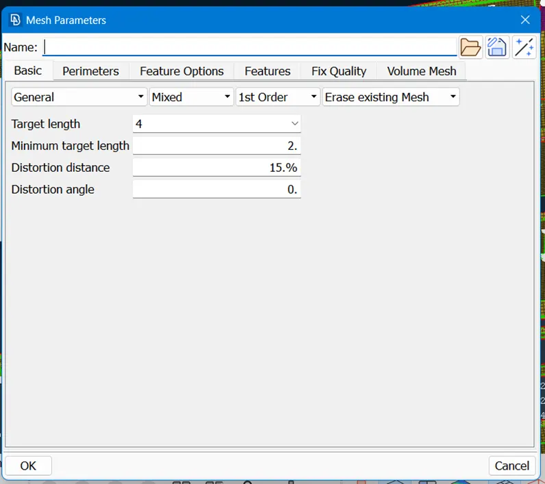
12. Generate mid-mesh by casting method:
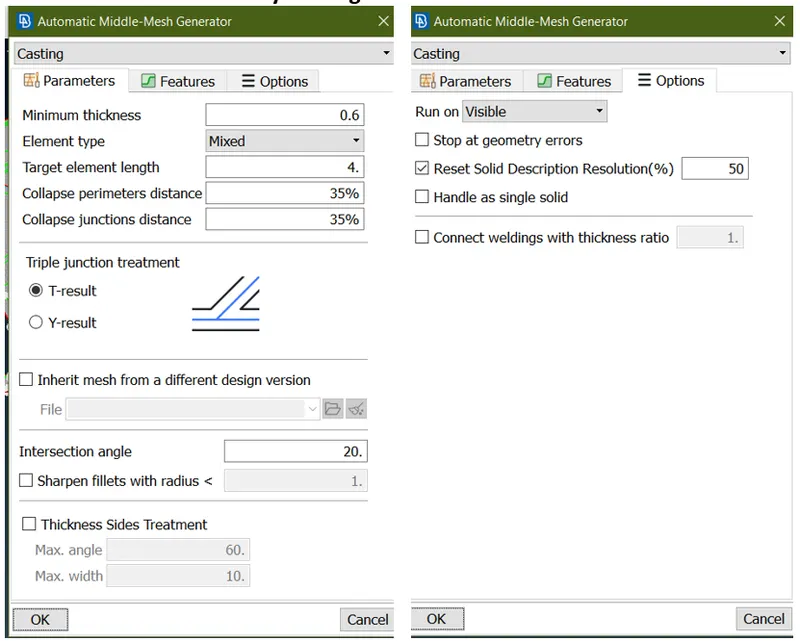
This makes the component get the desired shape, So it will be easy to extract a mid-mesh without any errors.The possibility of errors will be less.
To give perimeters and macros length on the components,
Go to (Mesh Module >Perimeters>Length)
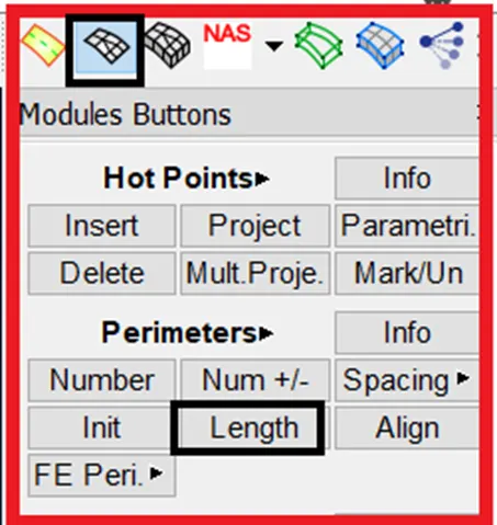
Similarly, do the same thing for the macros also.
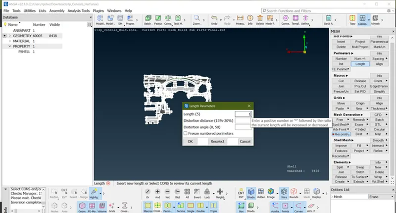
Why to Extract Mid Surface ?
Before extracting the mid surface for every component,We should measure the thickness of the component and then we have to proceed to extract the mid surface.
If the component thickness is less than 6mm then we will come to know it is a sheet metal component.
Below image represent casting process. Once casting is done mid-mesh are hidden in present geometry to visible mid-mesh by using Faces off to switch to micro option and open align manager by
(TOPO > Faces>mid surface > Align manager)
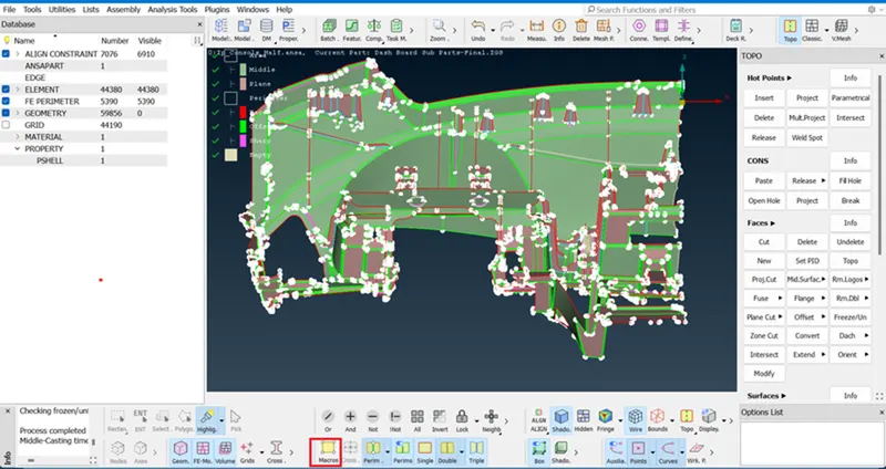
For sheet metal and plastic components, Mid Surface extraction is a must. In this project, I'm using the Casting method to generate MID-MESH.In this method, we generate Mid-Mesh takes very less time as compared to another method.
30 min taken to generate Mid-Mesh automatically by using the Casting method.
Switch Topo to Classic mesh to show the mesh.
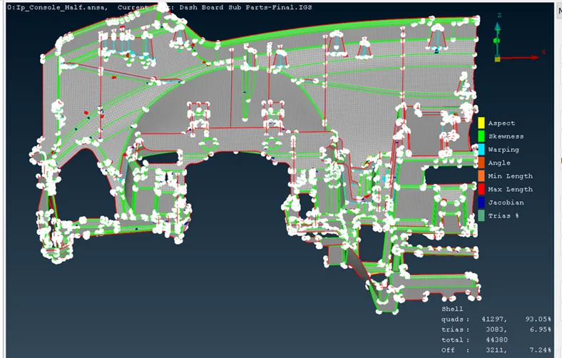
The below image is after the completion is done.
- Off Element - 3211 - 7.24%
- Trias - 3083 - 6.95%
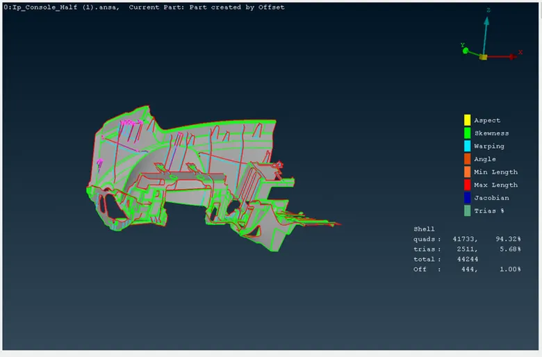
Below image result is appropriate and achieving 1% off element and 5.68% of Trias.
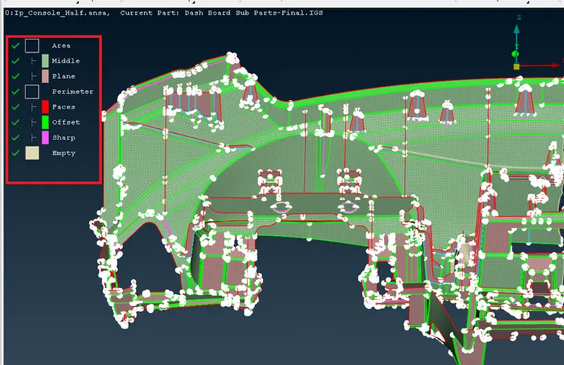
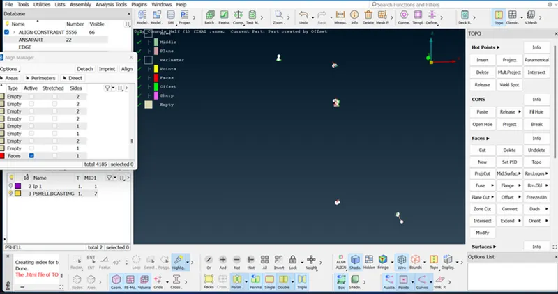
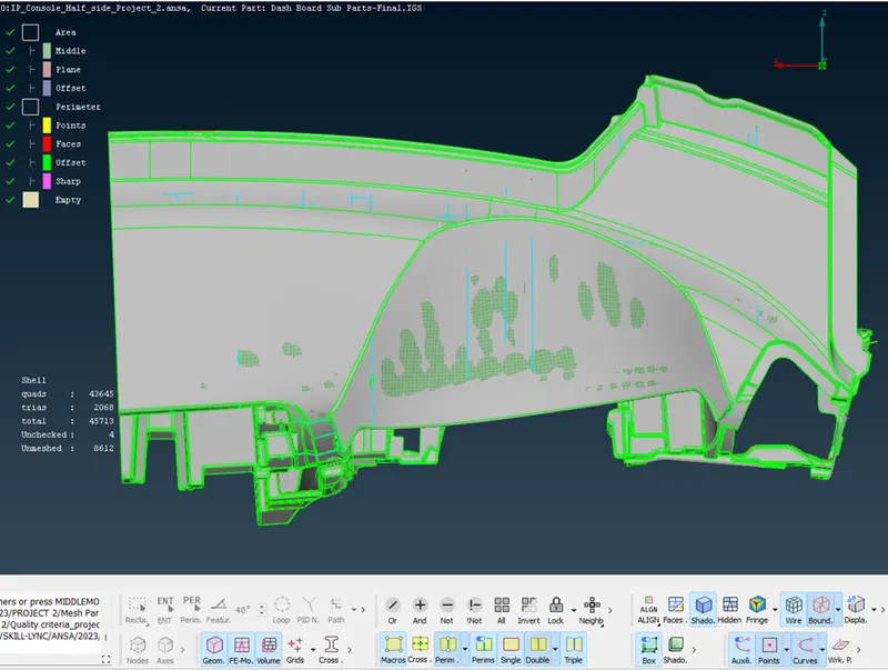
In the Casting process Align manager defines Area And parameter
Area -
- Middle - define Surface as a curvature (Green colour)
- Plane - Define as a Flat or plane surface (Pink Colour)
Parameter-
- Faces - (Red colour)
- Offset - (Green)
- Sharp - (Dark pink)
Empty - this will not define any surface and parameter and it should be eliminated by defining the surface properly.
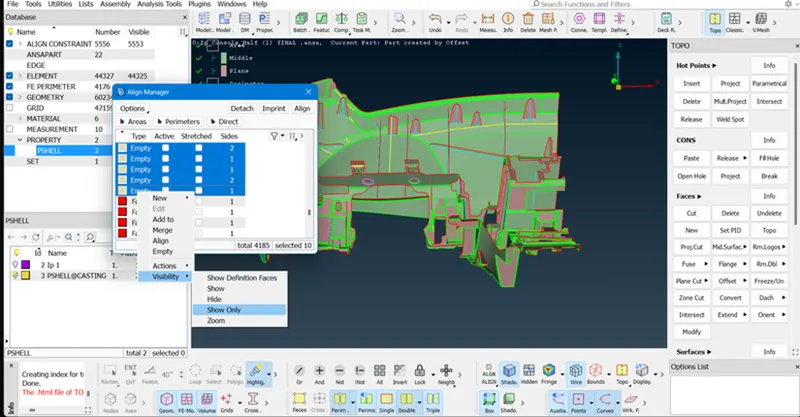
- View Empty by (Select all empty>right click of mouse>Visibility>Show only)
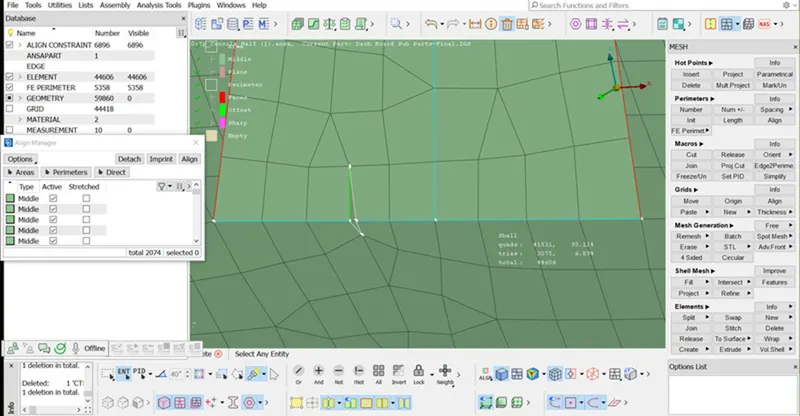
- Here is an empty surface as below image.
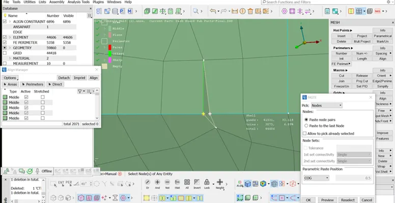
- To fix this kind of error by using paste option (Classic mesh>Grid>Paste>Select one node and second node>middle click of mouse)
- Once the pasting node is done then toggle the line which is not required by using the Right click of a mouse button.
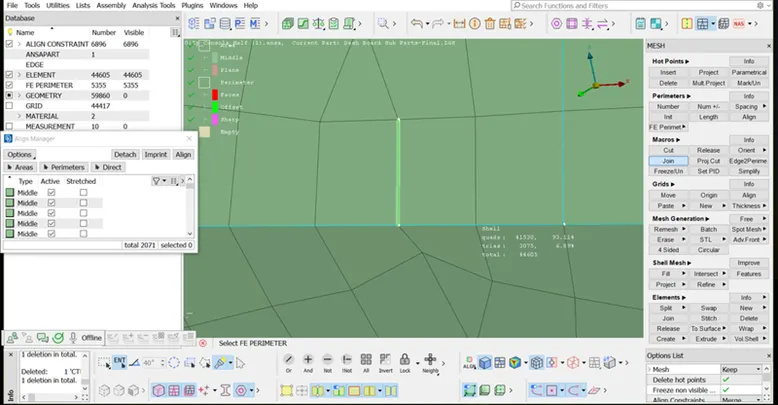
- Toggle the line by using (Classic mesh>Macros>Join>Select the line)
In the below image having an empty parameter first define it as a parameter line by using (Topo > Open align manager > Select the empty line > right click in empty > edit > faces > middle click)
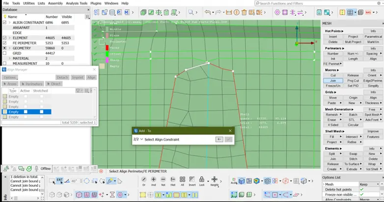
- Parameter assign. showing below image.
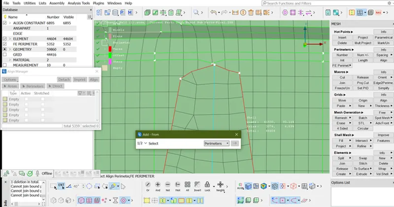
- In below image doghouse not in proper way because its having sharp edge first delete the surface and recreate the dog house by using delete option.
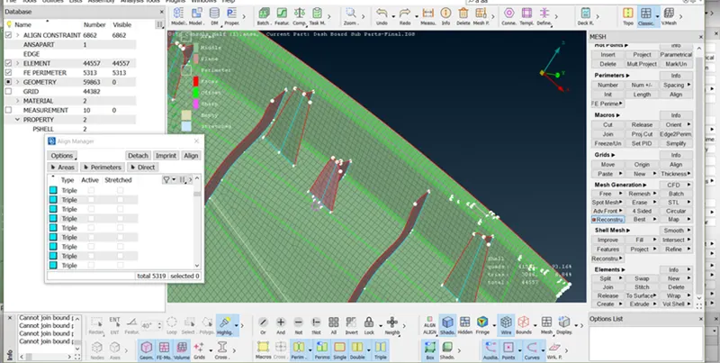
- Once the doghouse surface deleted than toggle all the white or empty edge by using (Classic mesh>Macros>Join)
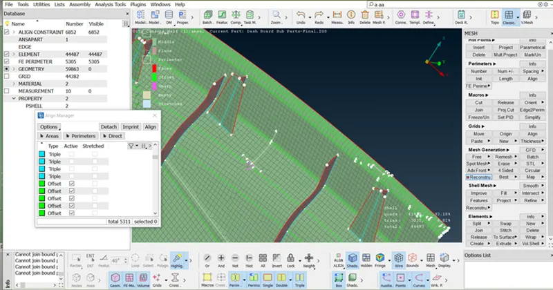
- Toggle the sharp edge line.
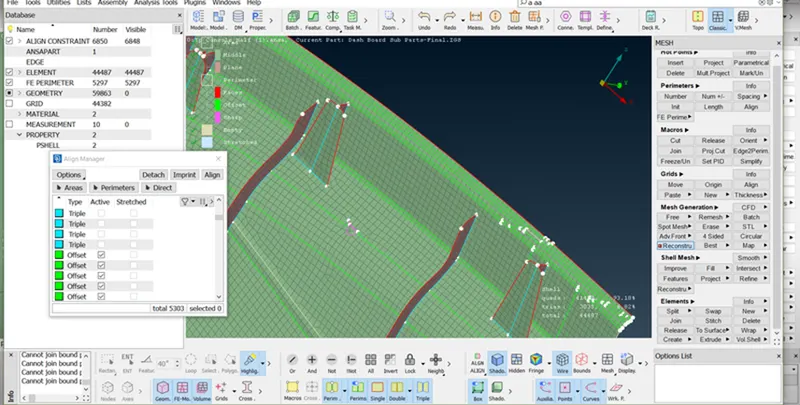
- Toggle the line or doing above operation construction line not in a straight way so first achieve straight line.
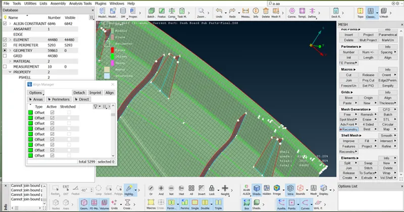
- Select the line and use Align manager, a two-point option.
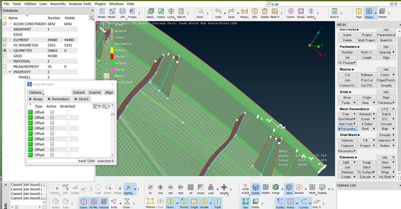
- To create the surface first by using (Topo > Curve > Create)
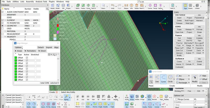
- To create the surface by using (Classic > Shell mesh > Fill > Select the curve/Parameter > middle click of mouse)
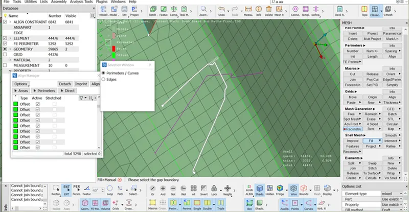
- Then Select method by changing from Draft to coons > OK
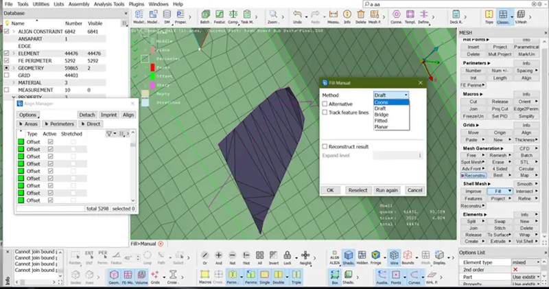
- The surface has been created as shown below image.
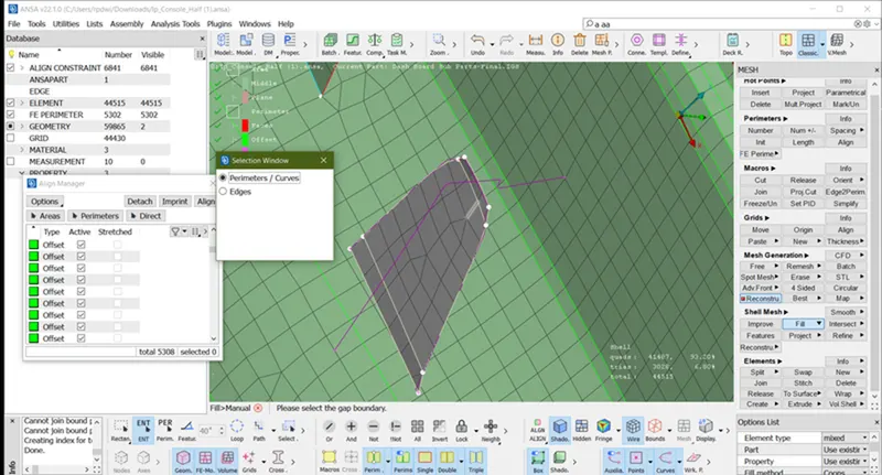
- Now create a second surface, first Go to
(Classic>Shell mesh >Project>select the Shells by macro >Next)
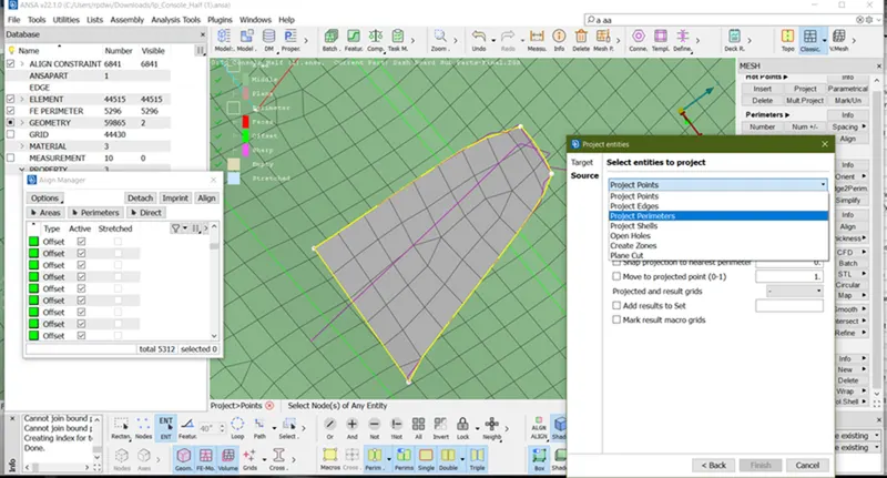
- Select entity to project Project Perimeters > Finish.
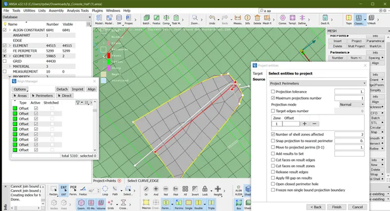
- A line is projected as shown in the below image.
- Once the line is projected toggle all the empty lines. By using (Classic>Macros>Join)
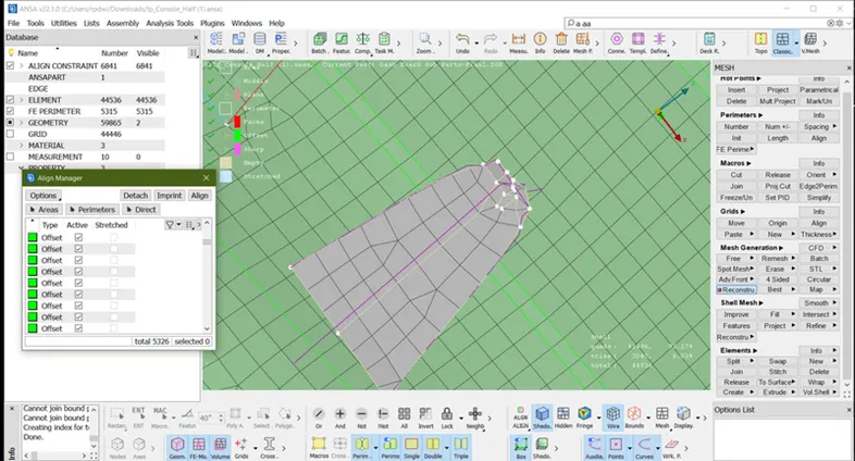
- A proper line projected and toggle unwanted line.
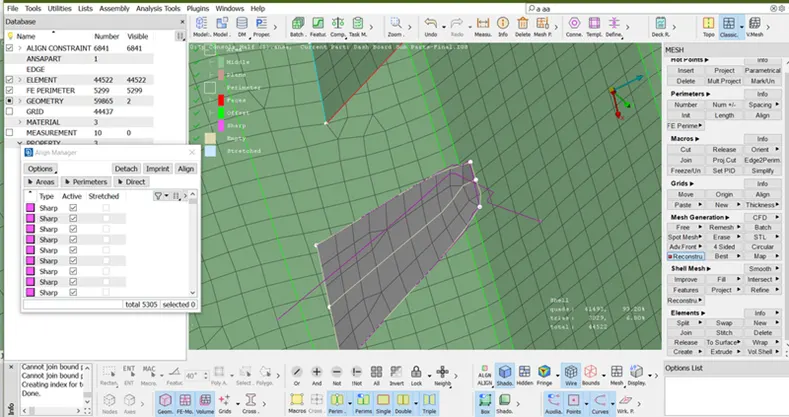
- Then create a surface.
(Classic>Shell mesh>Fill>Select the curve/Parameter>middle click of mouse)
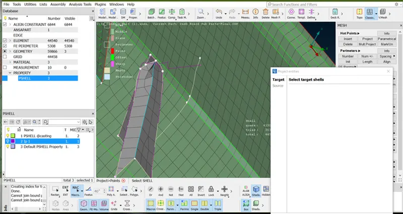
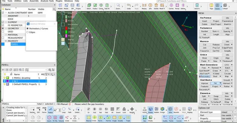
Then create back rib surface by using (Classic>Shell mesh>Fill>Select the curve/Parameter>middle click of mouse)
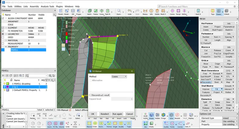
- The surface created and toggle all the unwanted lines.
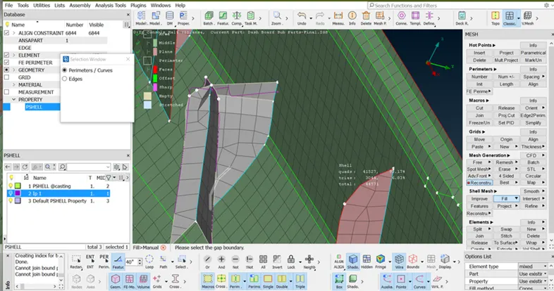
- When the dog house surface created but this dog house not attached into base surface so first joint dog house by using Paste option (Classic mesh > Grid > Paste > Select one node and second node > middle click of mouse)
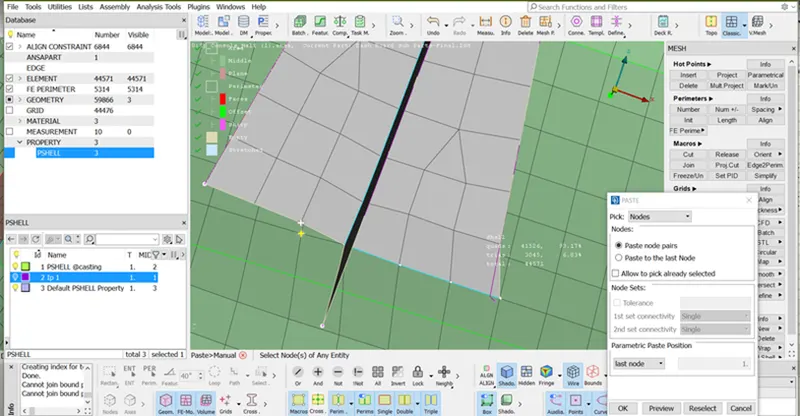
- Doghouse is attached as shown below image.
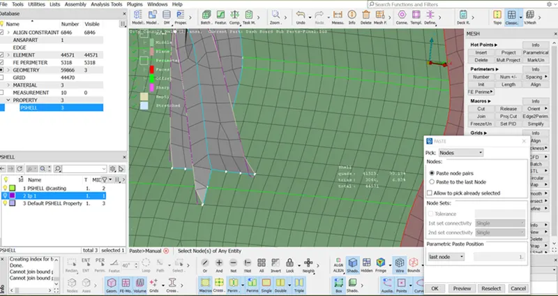
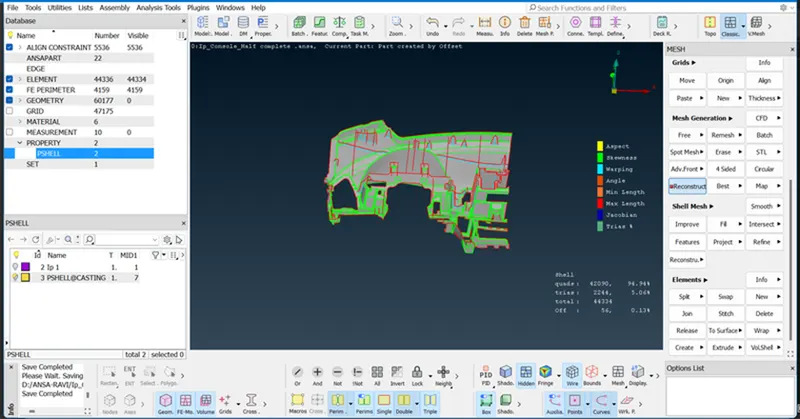
- Once the attachment is done now assign these empty surface into a define Middle or plane accordingly or delete the curve by using (Topo > Curve > Delete).
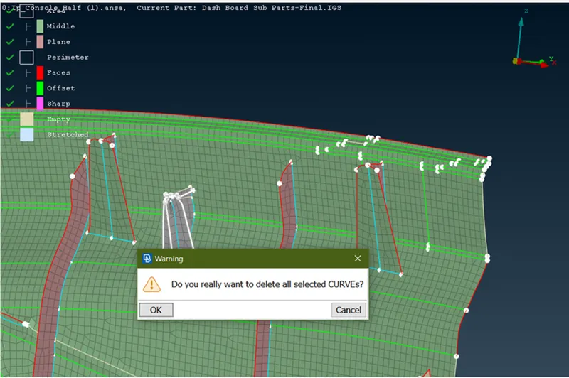
- Define the Surface following stages.
- Open align manager.
- Select the Shell by the macro.
- Right-click of the mouse on the empty Area and go to faces.
- Select the red and blue surface as shown below image then finish.
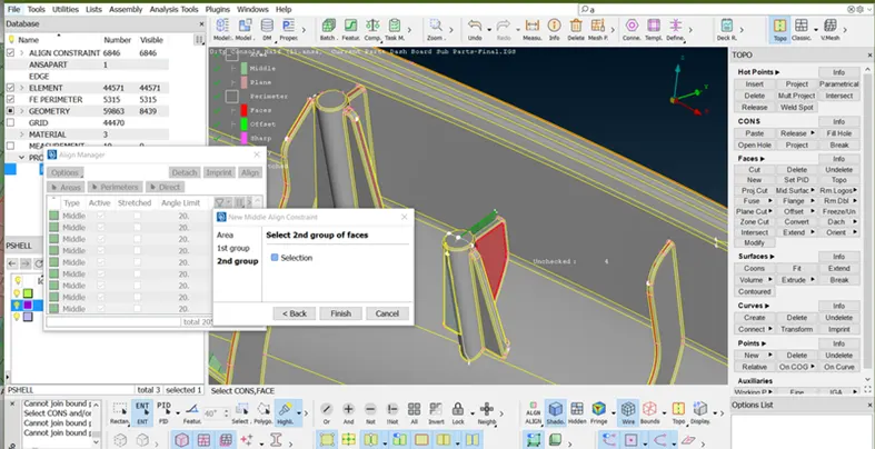
- Then assign every empty surface following the same as the above operation or align the constraints. Similarly doing operation on all the doghouse and ribs.
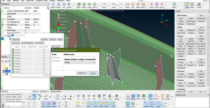
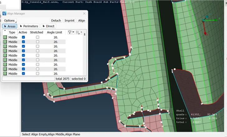
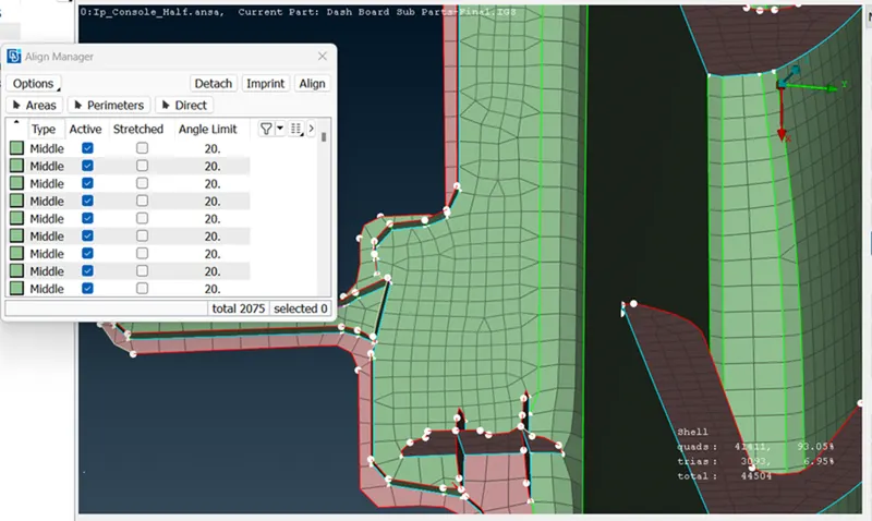
- As below image, this area is not proper and part missing so first resolve this area by following stages. First, toggle the unwanted line.
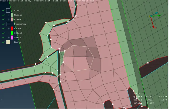
- After toggle, the line Surface looks like the below image.
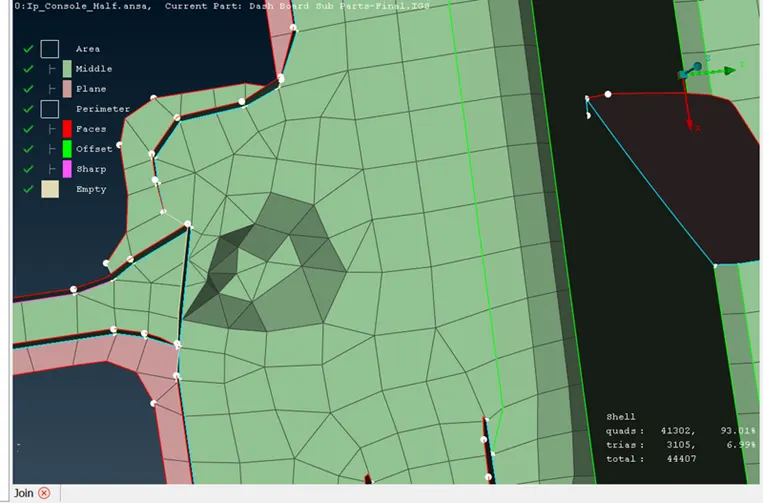
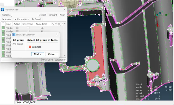
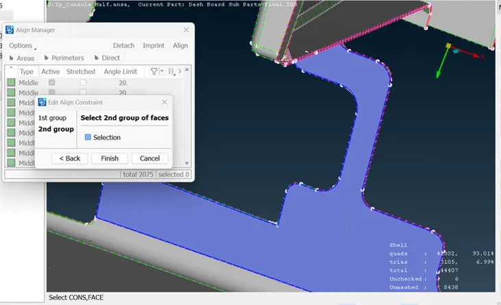
- First, define this area as a middle by following stages:
- Open align manager and select the dented surface
- Pop-up this surface into a align manager or highlight the area where this surface exists.
- Right-click the middle area.
- Go to Edit
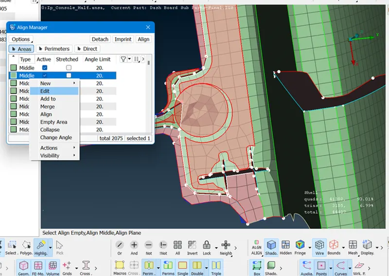
- Select red surface.
- Select the blue surface.
- The surface is Flat as shown below image.
- Reconstruct this area.
- Once the base surface achieves flat then create cross surface by using below stage
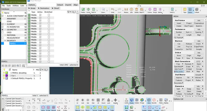
- To create the surface first by using (Topo > Curve > Create)
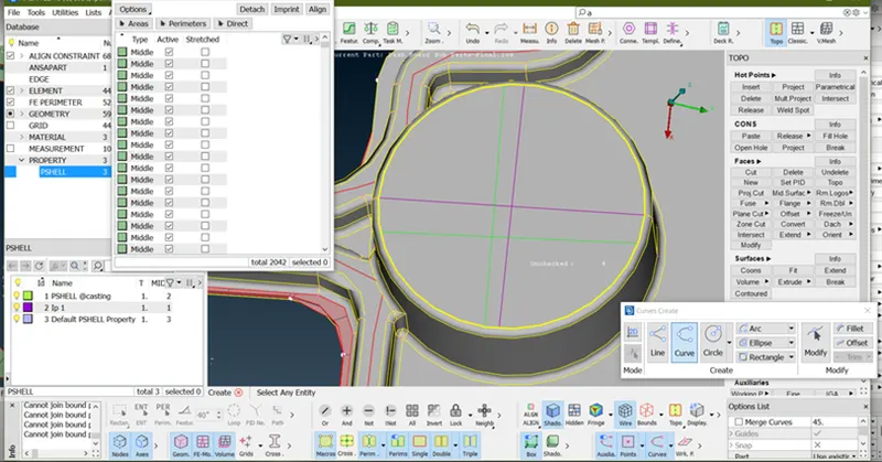
- Project the curve line in the base surface (Classic>Shell mesh >Project>select the Shells by macro >Next)
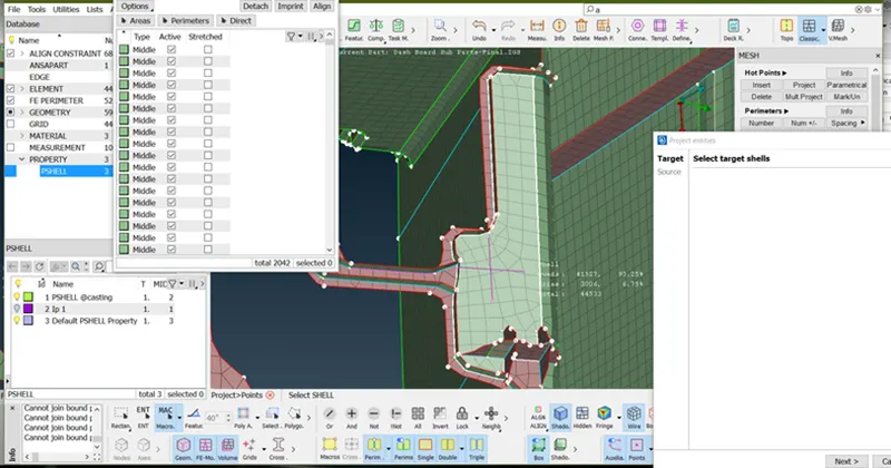
- Line projected.
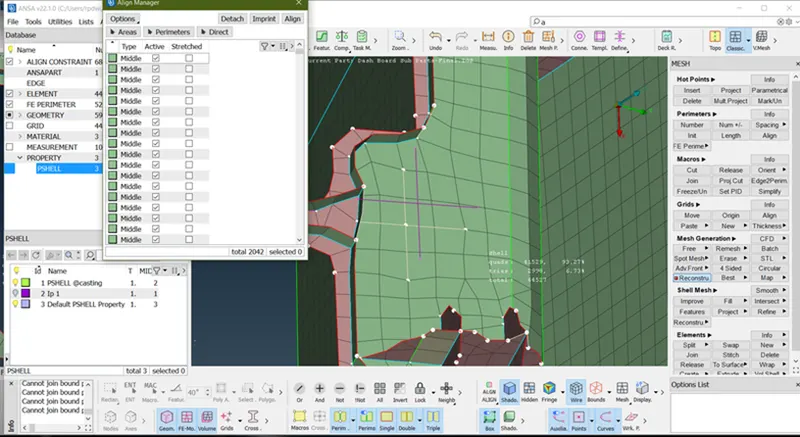
To create the surface by using (Classic > Shell mesh > Fill > Select the curve/Parameter > middle click of the mouse)
To Attachment this surface to the base surface by using (Classic mesh > Grid > Paste > Select one node and second node > middle click of the mouse)
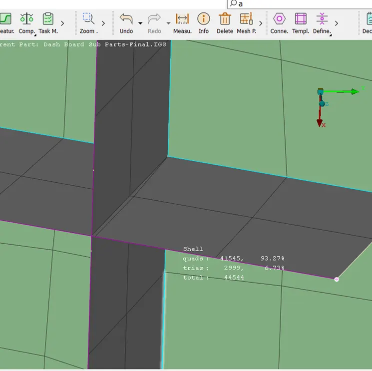
- As above image intersects two surfaces by using the paste option.
- Intersect surface as below image.
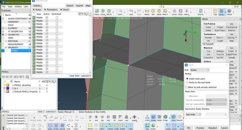
- Define this empty surface into a plane area by using Align manager>Add to function.
- The final image of this surface and element some trias as much as can.
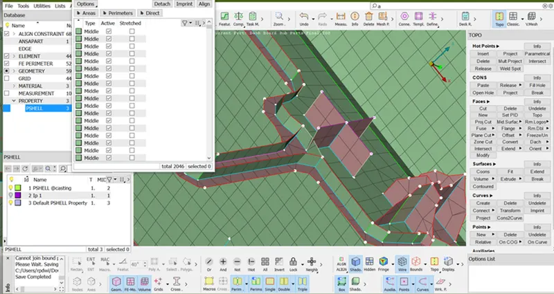
- Doing all the operation below is the final image.
- Also element all the empty areas and parameters.
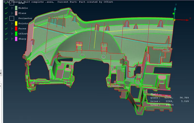
13. Assign Thickness to the Components: -
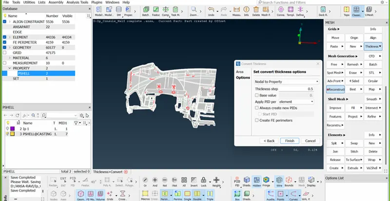
Creating thickness by using (Classis > Grid's > Thickness > convert select all All the element > Finish)
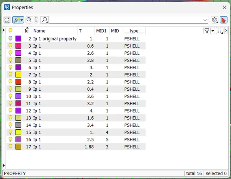
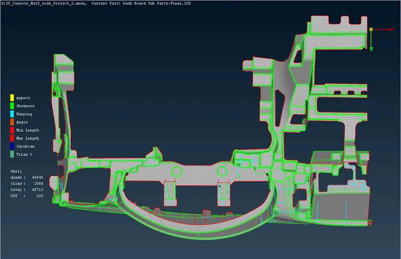
Final Image with Mid-mesh
In ENT Mode
In Align Mode
Applying thickness
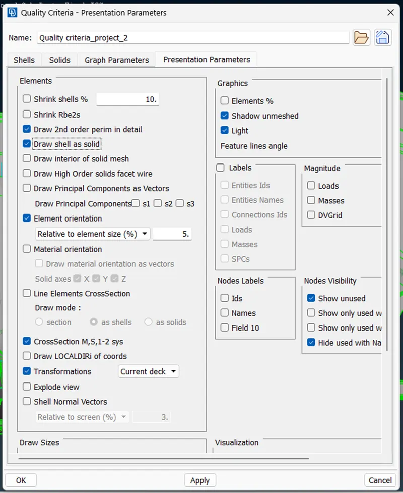
Quality criteria > Presentation parameters > Draw shell as solid
Final Model image with thickness applied.
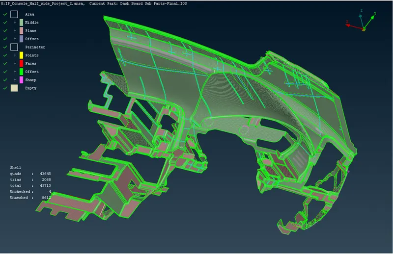
Result:
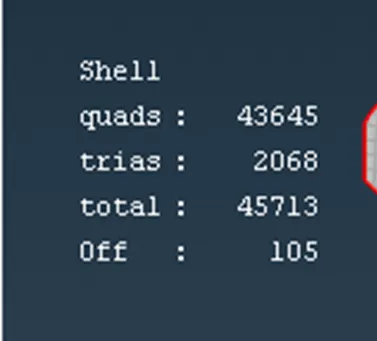
- Quads = 43645 (95.47 %)
- Trias = 2068 (4.5 %)
- Total = 45713
- OFF = 105
Note: There are some OFF elements in Triple con and some critical feature regions.
Learning outcomes:
In this project I learned the following things:
- to generate mid-mesh by using Casting
- to perform geometry clean-up for complex geometry.
- to define the middle and plane
- to create the surface while using the casting method.
- to extract mid-mesh for Ribs and doghouse.
- to achieve less Tria concentration with proper mesh flow.
- to clear failing elements from quality.
- to assign thickness by Automatic method.
Conclusion
- In this project, I have generated mesh using casting options in ANSA.
- Performed de-feature, line adjustments in some areas, topological clean-
- Understood Transparency mode and the concepts related to generating mid-surface for different features.
- Able to achieve better mesh flow using smooth, reconstruct, swap, paste, move
- Eliminated kinks and raised edges.
- Successfully generated mid-surface and meshed whole Instrument panel using ANSA.