Project 2 - 2D meshing on the instrumental Panel
OBJECTIVE
To extract the manual midsurface of the given instrument panel, mesh the component using the given quality parameters and assign thicknesses.
QUALITY CRITERIA
|
S.No |
Quality Criteria |
Value |
|
1 |
Target/Average length |
4 |
|
2 |
Minimum Length |
2 |
|
3 |
Maximum Length |
6 |
|
4 |
Aspect |
3 |
|
5 |
Warpage |
15 |
|
6 |
Skewness |
45 |
|
7 |
Jacobian |
0.7 |
|
8 |
Minimum Quad Angle |
45 |
|
9 |
Maximum Quad Angle |
135 |
|
10 |
Minimum Tria Angle |
30 |
|
11 |
Maximum Tria Angle |
120 |
|
10 |
Tria Percentage |
15 |
MODEL IMAGE
PROCEDURE
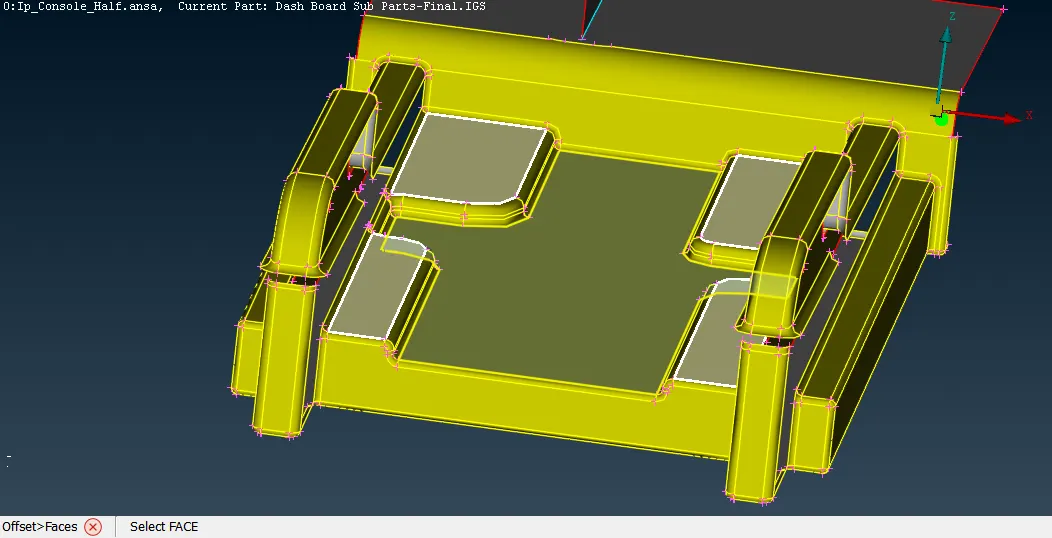
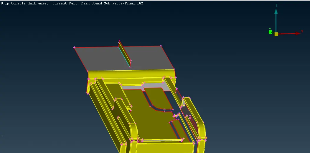
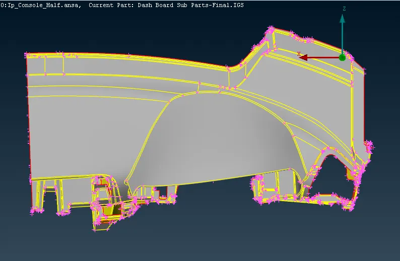
1. Firstly, we need to use the topo tool to take care of all the single cons and to ensure there are no free edges. It can be accessed via Faces > Topo in the topo module. All the cons are selected and the algorithm takes care of all the single cons.
take offset
2. After that, as is the norm and before we carry out any other actions, we need to carry out a geometry check and fix all abnormalities. That is done via Checks > Geometry where we can execute checks of certain defects that can be selected from the menu and the algorithm looks for said defects. After detection, we can select all the defects and right-click > fix to fix them.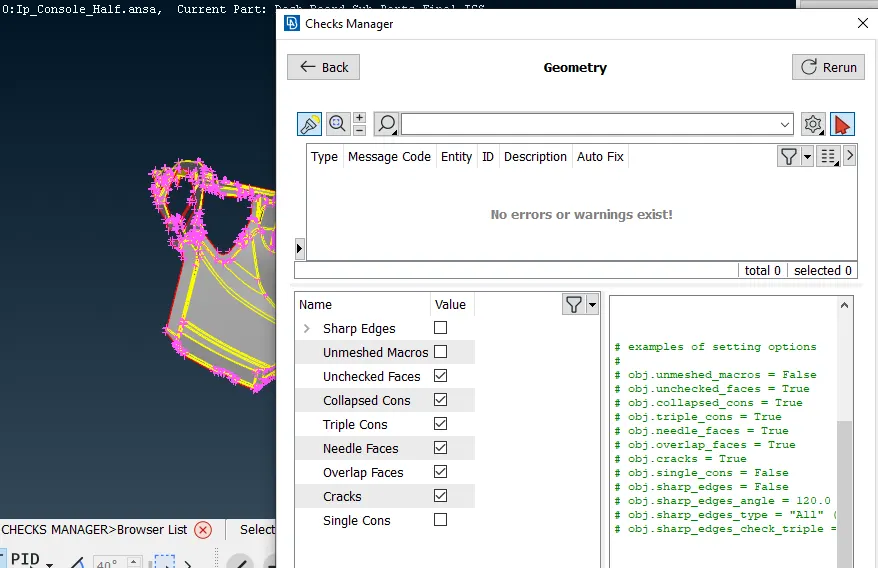
3. After orienting the model, using the Faces > Orient tool, we can go ahead and measure thicknesses of various regions in the component using the Measure tool from the top toolbar.
4. Now to generate the midsurfaces. There are multiple ways to do this. We shall be using the 'middle' and the 'offset' tools for this challenge.
For the base of the panel, offset tool can be used (Faces > Offset), it will ask us to select the surfaces to offset. We can select the surfaces on one side of the component. After that, we can assign the offset value (half the thickness). The offset tool will show the direction of the offset in the form of an arrow. If it is in the opposite direction of the required offset, the offset value needs to be in the negatives. If we proceed, the surface will be offset and we will have the option of keeping the parent surfaces.
As a sidenote, it is best to create properties for each of these midsurfaces as soon as you create them. Just as in the stored lock views, properties can also be helpful in facilitating your workflow and helps focus on a certain region.
The middle tool is especially useful for generating midsurfaces for the various ribs in this model. It can be accessed by going to Faces > Middle. After that, we just need to select either side of the rib and that generates the middle surface.
5. Another thing is, sometimes, the midsurfaces generated may be improper and might require fixing. In most cases, either using the geometry check tool or deleting the defaulted surface (Faces > Delete) and replacing it with a new one (Faces > New) usually fixes the problem.
6. For the doghouses, the midsurface for them can be captured using the 'cross pattern' since they are solids (hollow inside) and don't have a 'thickness' for us to define via ANSA.
To do this, one way is to use curves generated from the doghouse outlines. This is done using the Cons2Curves tool (Curves > Cons2Curves) from the topo deck. Simply clicking the outline and middle-clicking generates the curves. If there are regions without cons, we can simply create curves using Curves > Create to form the outlines.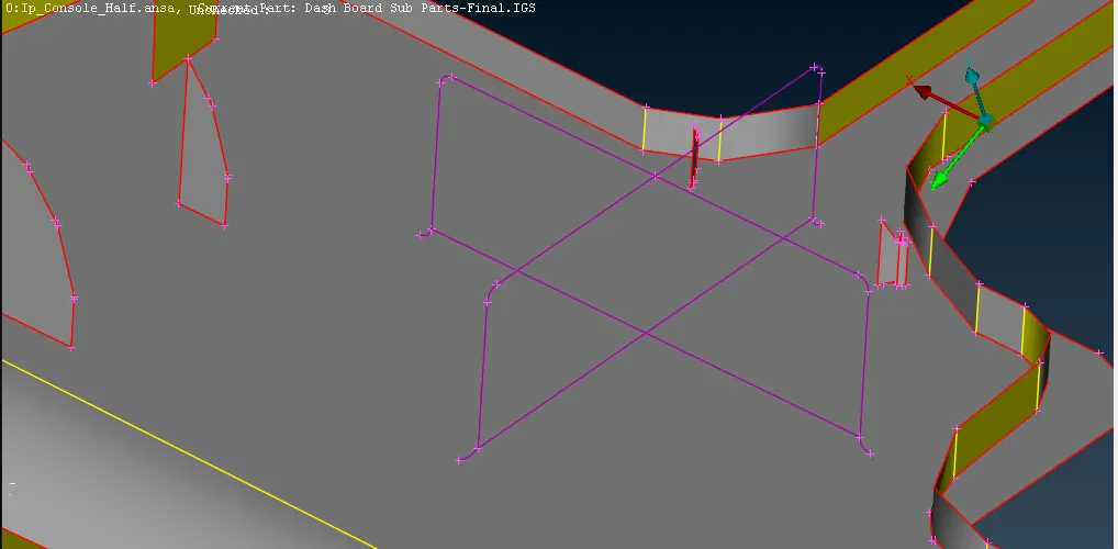
Then we can generate the surfaces using the Faces > New tool to form the doghouse cross pattern.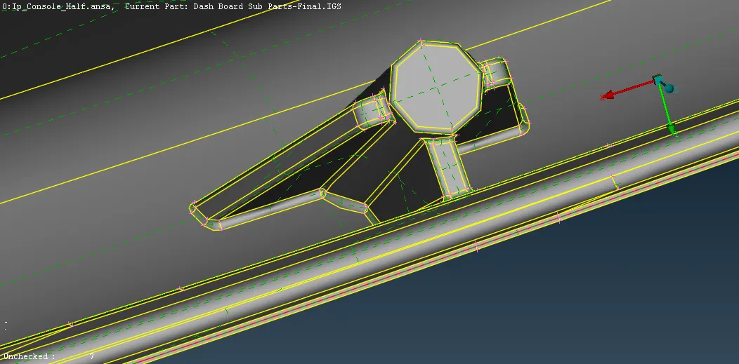
Dog house mid surface can be capture using tool cons2curve.
dog house in this model should be capture as Cross Pattern in the midsurface since dog house has solid hollow in inside and not having any thickness.
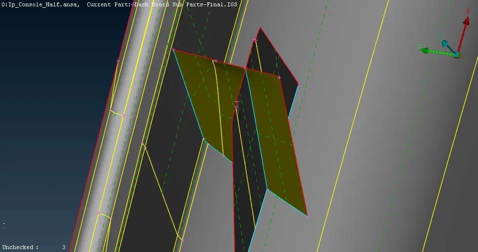
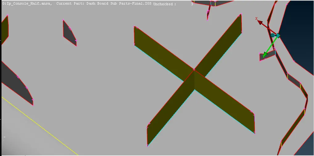
- 7. After extracting all the midsurfaces, we can go ahead and extend them to each other to join them with their adjacent counterparts. That is done by using the Faces > Extend tool and selecting 'target'. This option helps extend the edges of surfaces to target faces.
8. We can go ahead and assign the thickness property for each of them using the properties. To set a property ID (PID), we can go to Faces > Set PID from the topo deck to create and set a new property ID. This opens a new window where we have the option to edit many of the particular property's attributes. In this case, we are to assign a thickness (T). We can go ahead and assign the thicknesses. The process will be repeated for each of the components' midsurfaces. We can do the same and assign properties for the main components. The intention is to view the midsurfaces (and their mesh) and parent surfaces separately.
9. Finally, to ensure there are no minimum length failures for mesh elements, we will need to suppress/toggle certain cons that have hot points/nodes that are too close to each other (and can result in element lengths smaller than the required 2mm). This is done by right-clicking the cons using the Faces > Cut tool.
10. Now, having generated midsurfaces for the entire component, we can proceed with meshing. Before meshing, we need to set the target length (through perimeter > length). With that taken care of, we can assign the other parameters. This is done by accessing mesh parameters and quality criteria from the top toolbar.
11. We can then start meshing the entire component (using Mesh Generation > Best from the Mesh module) starting from one region and spreading out. It is ideal to start from a region with more single cons surrounding it.
12. After that, we can make use of the reconstruct tool (Shell Mesh > Reconstruct) to generate a better mesh if the initial mesh is not satisfactory.
13. Sometimes, the reconstruct tool doesn't work in getting rid of some trias. Trias are okay but certain types of trias need to be avoided - like opposite trias or trias touching feature lines. Trias can be worked on using the swap, split, join and smooth tools. The first three are available in the 'Elements' section and the smooth tool is available in the 'Shell Mesh' section. The following example shows the tools in action:
14. We can simultaneously switch to hidden mode (from the bottom toolbar) to check mesh quality and work on improving the mesh. The cycle of meshing, reconstruction and tria removal + smoothing is carried out throughout the entire component.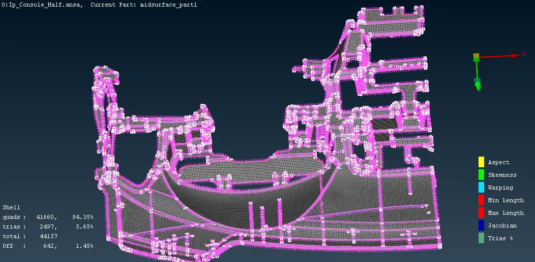
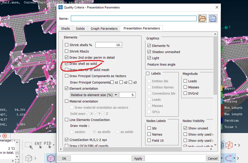
15. Finally, after we finish meshing the entire component, as required, draw shell as solid needs to be activated. This can be done by going to Quality Parameters and accessing the Presentation Parameters tab. In that section, the 'Draw Shell as Solid' box needs to be checked.
FINAL MESHED COMPONENT IMAGES
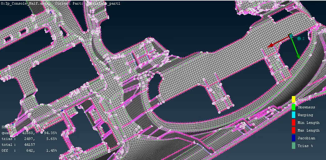
642 Off elements could not be avoided due to certain features' orientations and their measurements, especially that of the ribs.
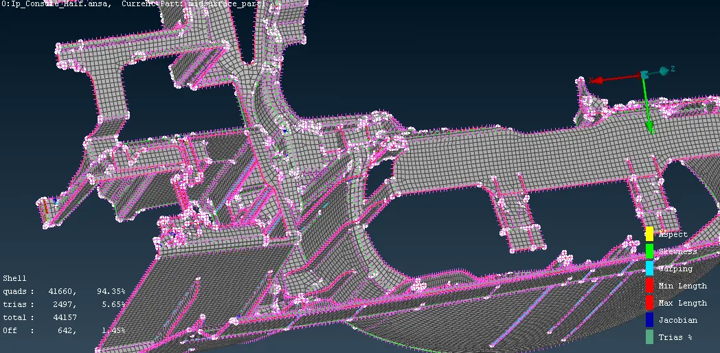
With thickness enabled:
LEARNING OUTCOMES
1. Learnt to work on doghouses from a midsurfacing aspect.
2. Learning on improving mesh flow since mesh flow is something that cannot be absolutely perfect in components such as this.
3. Was able to make extensive use of the extend and intersect tool in this project.
CONCLUSION
The given Instrument Panel model was midsurfaced and meshed as per given requirements and due to many small regions and
boundary restrictions due to rib placements, there are some unavoidable off elements. Ensured mesh flow was as good as possible.
please find the below drive linc for the access the model, i am not able to upload the file due file contain more than 20 MB.
https://drive.google.com/open?id=1-9minbstspbZ6j4OtiwZO3U4NpldPfsz&usp=drive_fs
https://drive.google.com/open?id=1-9JNl6rsI21y8GHgJmEhnui4ivyceqpZ&usp=drive_fs