Project 2 - 2D meshing on the instrumental Panel
AIM
To Pre-process the given instrumental panel or the dashboard of an automobile using CAE-ANSA by Casting method.
GIVEN
- Model in .ansa format.
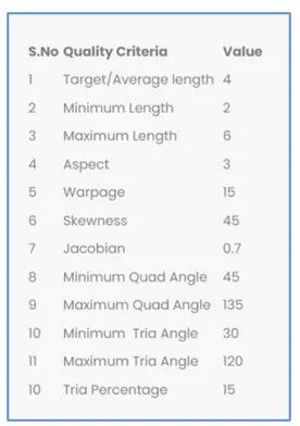
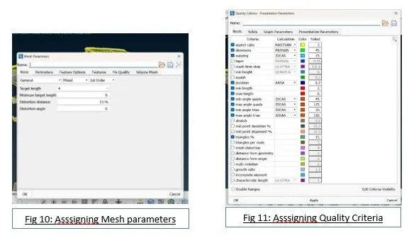
- Quality Criteria for the Shell Mesh:
OBJECTIVES
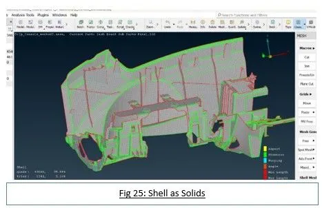
To pre-process the given IP by generating mid-surface and mesh using casting method. Applying thickness and draw as solids.
METHODOLOGY/PROCEDURE
1. Import the geometry:
The given .ansa model file will be imported into ANSA in this process. To get start with the analysis of the given FE component – for geometry cleanup in a very effective way.
2. Topo:
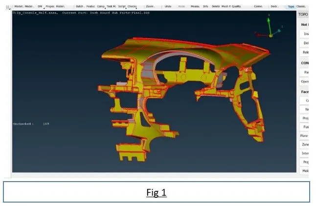
Topology should be done in-order to stitch the surfaces together. Topo command can be accessed in Topo deck ----> Faces ----> Topo.
3. Geometry Checks:
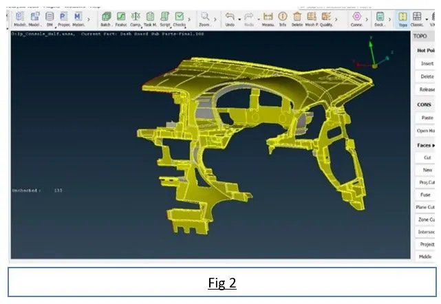
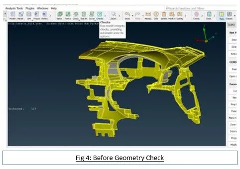
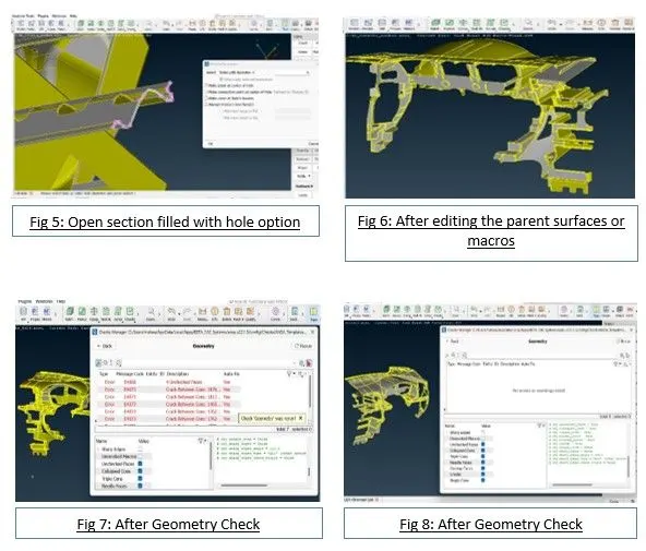
Geometry checks should be carried out to ensure whether the given surface of the component is out of geometrical errors or issues in the form of extra surfaces, triple cons, needle edges or faces, etc. If error found, it can be fixed by either auto fix option in the ANSA or by manual method. Geometry check command can be accessed in Tool bar ----> Checkup ----> Geometry. Before checking for geometrical error, the given IP should be inspected for regularity and uniformity. This can be done by either smoothening the surfaces by assigning significantly least length perimeter or by fine tool. Former method of assigning length perimeter is done in the given case and the surfaces are inspected. The command can be accessed by Mesh ----> Perimeters ----> Length ----> Perimeter/Macro = 4mm. The component after assigning perimeter and carrying out geometry checkup are shown in Fig (3) to Fig (8).
4. Thickness measurement:
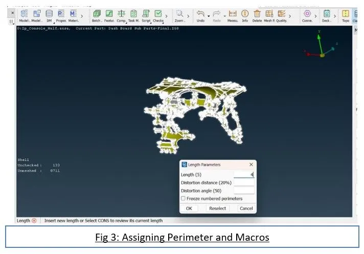
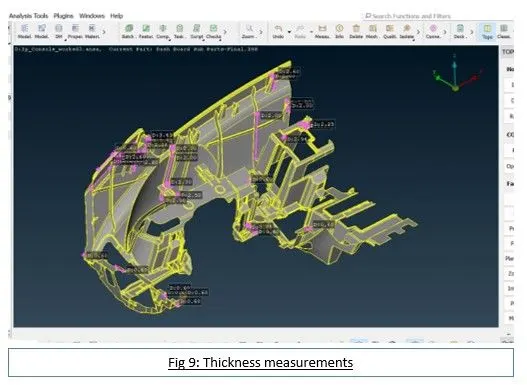
The thickness should be measured throughout the critical areas of the components as per the geometry demand. However, sheet metal components have uniform thickness while plastic components have non-uniform thickness throughout the component. The command can be accessed in Utilities bar ----> measure. It is up to the engineer’s discretion to measure the thickness with the node or cons or faces options as per the component demands. The components with measured thickness are shown below:
5. Assigning Mesh parameters and Quality Criteria:
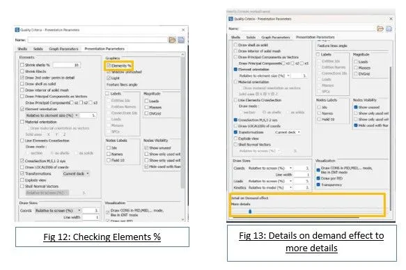
Assigning of mesh parameters and quality criterial carried out as shown in Fig (10) and Fig (11).
6. Casting Method:
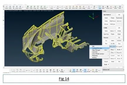
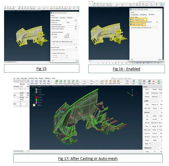
This is an automated method for meshing the component as shown in Fig 14. The command can be accessed by Topo ----> Mid-surface ----> Casting/Extrusion. Auto-middle mesh generator window opens after selecting the component as shown in Fig 15. After assigning the target element length = 4 and minimum thickness = 0.25 in the mesh generator window, hit OK to generate mesh and is shown in Fig 16. Since there are many features present in the parent geometry, they all get disrupted or getting deformed according to the complexity of the form of their geometry after casting. Fig 17 shows the extent of deformation the features under gone during the process.
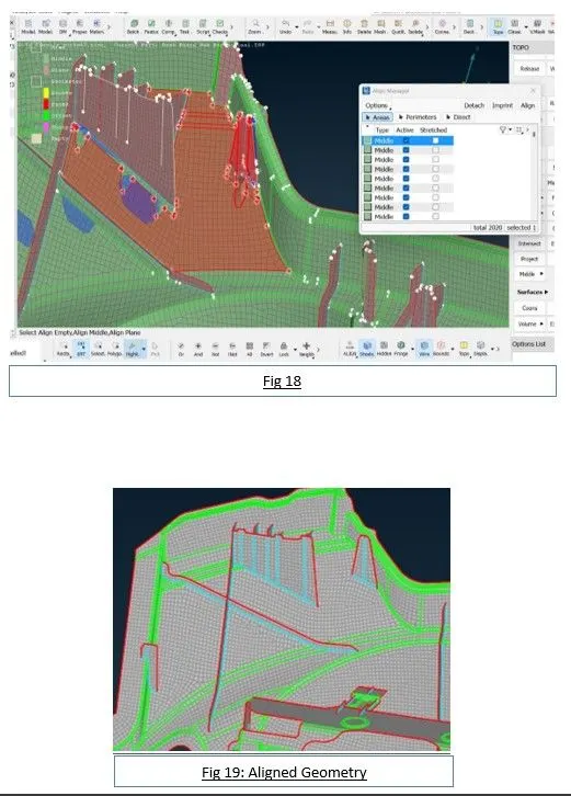
This need to addressed and restored to their original form as close as possible. To restore, align manager tool comes as handy. Align manager can be accessed by Topo ----> Mid-surface ----> Align Manager. In align manager, perimeters for aligning cons and areas for aligning macros as per the geometry of the parent component is utilized.
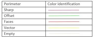
The default color assigned for perimeter –
The default color assigned for areas –
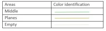
In above two categories of perimeters and areas, empties need to assigned and get rid of. There are prescribed techniques involved in assigning cons and micros to appropriate parent geometry feature and getting rid of empties. And one such example of assigning appropriate geometry is shown in Fig 18. Here middle is misaligned to the dog house as well, so it is cleared off from the selection and exactly aligned to the base form of the geometry as shown in Fig 19. The activity is same so do with the selection and deselection of cons as well under Perimeters.
In this process of aligning and restoring the form of the geometry, various tools have been used in appropriate demanding locations. Those tools are create curves and cons2curve under Curves; middle under Faces; align under Grids; insert and delete hot points under Hot Points; spot mesh under Mesh Generation; various commands under Shell Mesh; and various commands under Elements.
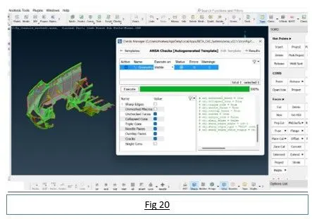
After completing alignment and clearing of the Off elements to maximum extent with remaining 50 offs elements remaining, which cannot be cleared off due to complexity of the geometry of the model itself after meshing, the resultant meshed aligned model is again checked for geometrical errors and is shown in the Fig 20.
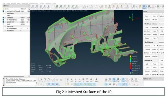
The final meshed surface of the geometry is shown in the Fig 21.
7. Assigning PID:
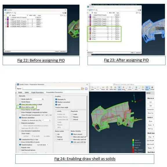
PID need to be assigned to the created meshed middle surface. For this thickness command is used. This command can be accessed by: Mesh ----> Grids ----> Thickness ----> Convert ----> Selection (area). PIDs will be assigned to the surfaces or locations of the model of different variations in thickness as shown in Fig 22 and 23.
CONCLUSION
Hence, the given component – Instrumental Panel of an automobile is meshed after extracting the mid-surface by auto-mid or Casting method as per the given quality criteria. The thickness is assigned to the meshed component and graphically represented as draw shell as solids.
Learning Outcome
- Hands on experience on ANSA Pre-processor tool. With collective working experience in Casting and Mid-surfacing.
- Attained valuable knowledge in Align Manager tool.
- Familiarized with ANSA tool while working with the model, which instills much faster working with the ANSA tool in the future challenges.