Project 2
Two DC/AC H-bridge inverters are connected to a point of common coupling of a micro-grid system. The inverters are fed from voltage sources and are importing power to the micro-grid, to feed an AC load of 5 kW & 2 kVAR. The micro-grid AC voltage amplitude is set at 170 V, while the micro-grid operating frequency is 60 Hz. The DC sources (V_s1 and V_s2 ) operate at a DC voltage of 220 V. Inverters 1 and 2 have capacities of 4 kVA & 3 kVA respectively. While C_1 &〖 C〗_2 are sized at 2 mF. R_1,L_1,R_2 & L_2 represent the line impedance and can be ignored in this problem.
Figure 1. Micro-grid System for two parallel inverters.
- What are the values of the passive components (R, L, and⁄or C) that you can use to model the active and reactive loads?
- Design the droop control parameters of the inverters to ensure that the micro-grid operating voltage and frequency are within 0.5% of their respective nominal values at the aforementioned load conditions.
- Simulate the circuit and show complete results including the delivered load active and reactive power, the micro-grid operating frequency & voltage, the active and reactive power sharing of every inverter, etc.…
- Apply a sudden change in the active power load by dropping it 3 kW after it reaches steady-state and verify that the power-sharing between the two inverters is maintained.
- Show the simulation plots for the above case and comment on it.
- Apply a sudden change in the reactive power load by increasing it to 3 kVAR after it reaches steady-state and verify that the power-sharing between the two inverters is maintained.
- Show the simulation plots for the above case and comment on it.
Case study:
Two H-Bridge DC/AC inverters are used for the microgrid.
AC load is 5KW and 2KVAR.
AC amplitude is 170V
Frequency: 60Hz
Vs1 and Vs2 are the DC sources with an operating value of 220V.
Inverter_1 capacity is 4KVA
Inverter_2 Capacity 3KVA.
C1 and C2 are sized as 2mF.
R_1, R_2, L_1, L_2 can be ignored.
As Output Voltage amplitude Vo =
I/p AC voltage = 220V
= 0.772
Amplitude Modulation ratio
Freq modulation ratio = Fc/Fr
Fcà carrier wave frequency = 1MHx
Frà ref wave frequency = 50Hz
Load KVA: sqrt((Kw*KW) +(KVAR*KVAR)) = 5.38 KVA
Peak voltage is 170V and Vout _rms = 121V
I_out RMS = 44.46A
Impedence = V/I = 2.721Ohms
Resistive Load: Active power is I*I*R = 5000Watt
Based on the above calculations, below is the simulation diagram in the Simulink.
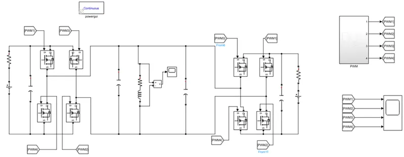
In the simulation, PWM signaling is done with Bipolar switching.
Which is shown below.
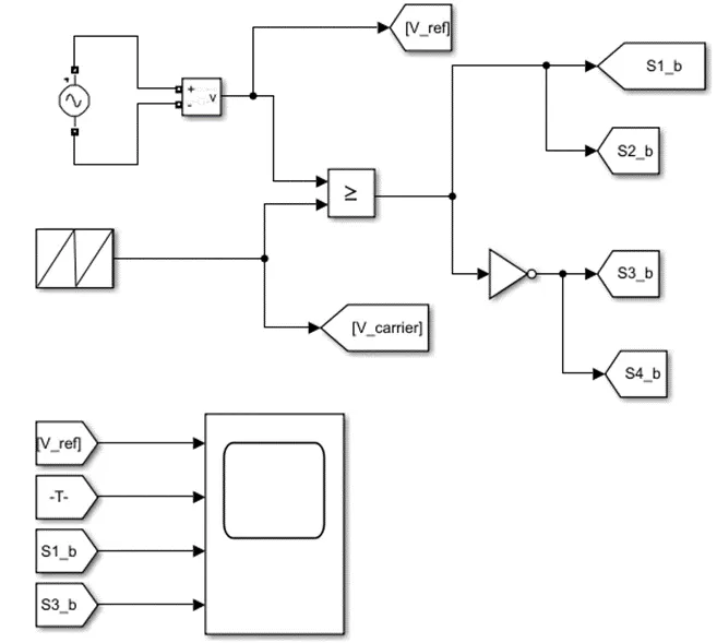
The circuit’s PWM signaling is as shown below.
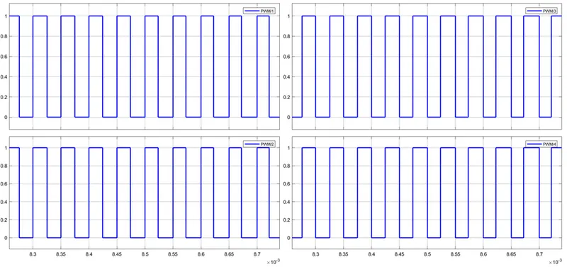
The above PWM signal shows that Switch 1, 2 are on and 3 and 4 are on at other times.
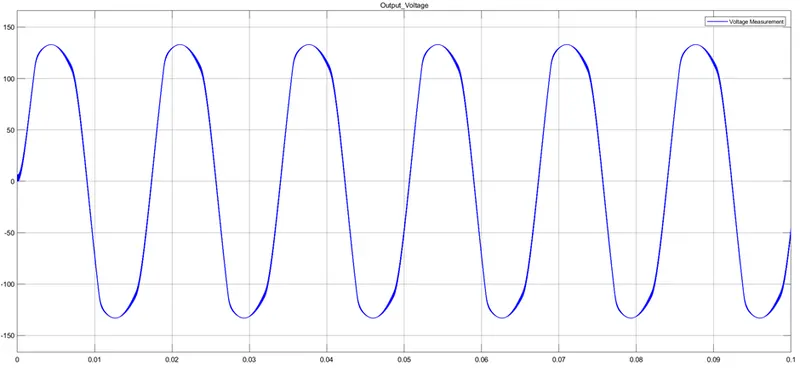
AC voltage output is based on the inputs as shown above.