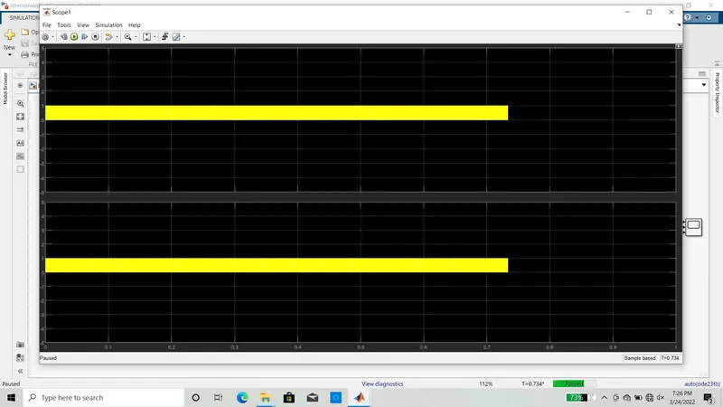
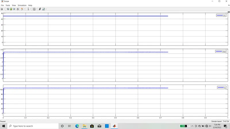
Project 2
PROJECT-2
Micro-grid System for two parallel inverters.
1. Design an interleaving DC/DC converter system for a data centre application with the following specifications:
• Input voltage: 45 – 60 v
• Output voltage: 3 V
• Output current: 100A
• Efficiency > 85% (extra credit for efficiency higher than 90% on a spice-based software simulation tool)
Simulate the system using a Spice-based software simulation tool such as LT-Spice, Pspice, PowerSim, TINA, etc...
Show your design in details (most probably, you will need to use an isolated system to achieve this low voltage conversion ratio, you might also need to use a multiphase system to increase the efficiency).
Show the input voltage, the output voltage, the input current, the output current, the system efficiency and any other simulation plots necessary to evaluate your design.
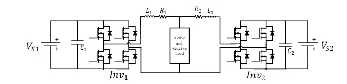
2. Two DC/AC H-bridge inverters are connected to a point of common coupling of a micro-grid system. The inverters are fed from voltage sources and are importing power to the micro-grid, to feed an AC load of 5 kW & 2 kVAR. The micro-grid AC voltage amplitude is set at 170 V, while the micro-grid operating frequency is 60 Hz. The DC sources (V_s1 and V_s2 ) operate at a DC voltage of 220 V. Inverters 1 and 2 have capacities of 4 kVA & 3 kVA respectively. While C_1 &〖 C〗_2 are sized at 2 mF. R_1,L_1,R_2 & L_2 represent the line impedance and can be ignored in this problem.
Model for the above statement is shown in the below figure. as per the requirements given in the above discription.
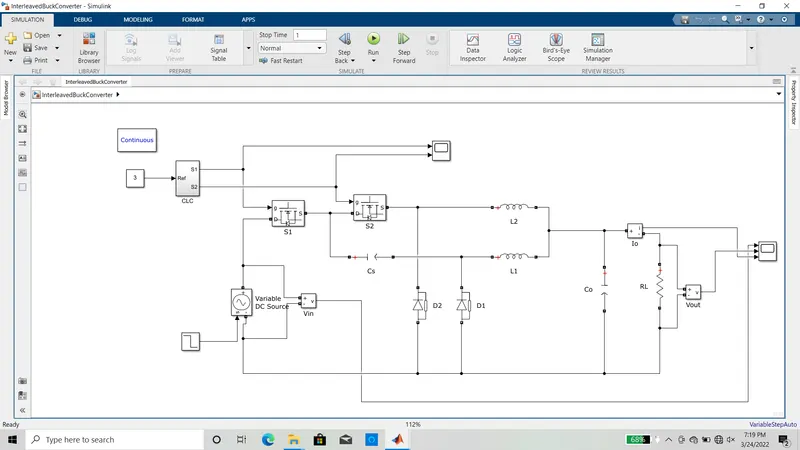
result for the above model is shwn in the below figures.