Project 1 (Mini Project on Vehicle Direction Detection
MINI PROJECT
ON
'VEHICLE_DIRECTION_DETECTION _MODEL'
AIM: Identifying the direction of the vehicle is one of the important & diverse features in Autonomous driving & Advanced Driver Assistance Features. This particular sub-feature of identifying the direction of vehicle is basically identifying the direction the vehicle is taking based on the camera input.
OBJECTIVE:
1) Model Development of MATLAB Simulink has done based on the given requirement and the below figure shows the model.
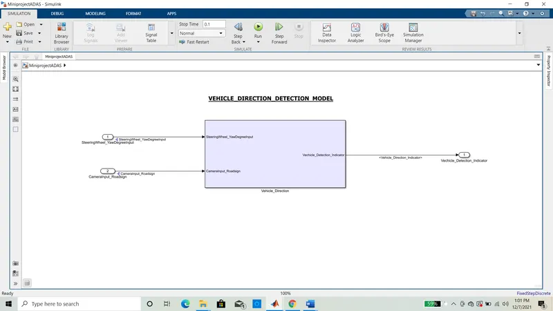
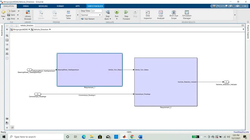
The above picture shows the created subsystem of 'Vehicle Direction'. We have two subsystem in vehicle direction containing 2 requirements (Requiremenr_1 & Requirement_2).
Requirement_1 & Requirement_2.
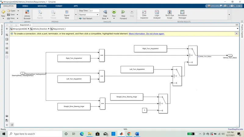
Requirement_1 subsystem is compressed with model, Constant Block is used to give the input and relational opreator block is used to compare the input and switch block is used is to obtain required output, this all is created in subsystem name the system as requirement_1. And rrequirement tagging has been done for each subsystem separetly.
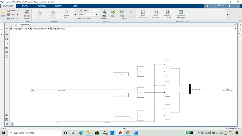
Requirement_2 is compressed of a model which has built made of using constant block the output of constant block is given to relational operator block output of relational operator is given to input of alogical operator and block and overall output is given to view the result.
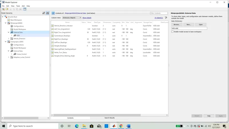
Below screenshot shows the simulink Data Dictionary which has been created for the model and the requirement given by the requirement manager, And the SLDD file is linked to the model.
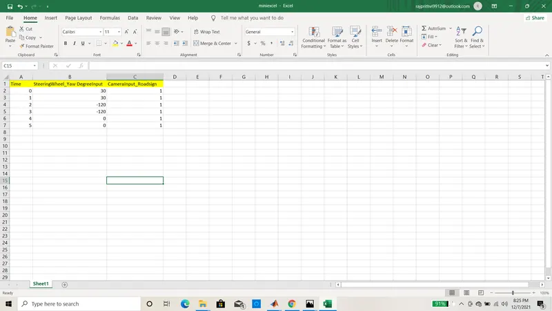
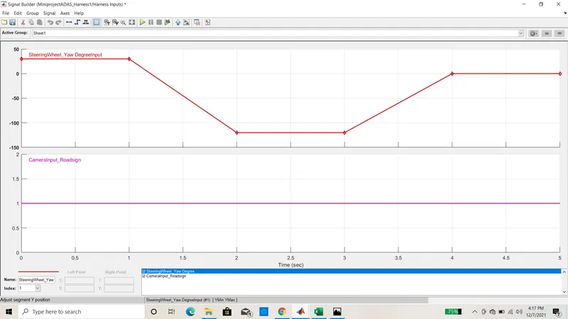
Excel sheet has been created for the tset singnals which we will given as input to model from signal builder block imported to block. In this from time 0 to 1 the angle is 30, from 1 to 2 the angle 30 to -120 etc..And this required when test harness is done to create MODEL IN LOOP and SOFTWARE IN LOOP.
Below picture shows that when excel sheet inported to the signal builder block the signals are shown below.
MODEL_IN_LOOP Template is shown below.
It has been done by creating susbsystem of model and right clicking on the model we will get test harness option tap on that in that create test harness system tap on that, it opens a window give input as signal builder block nad output as outport tap on the build option.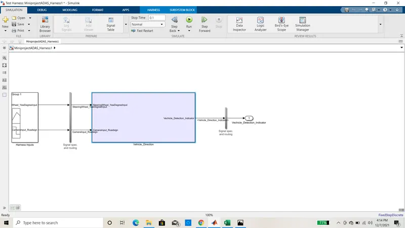
FUCTIONING:
Model is created and when we tap on the run button, There are two inputs for the model INPUT_1 SteeringWheel-YawDegreeInput this input is compared with 3 angular values 30, -120, 0 this angular values are having calibration names to say which specific direction the steering wheel is turning towards, When it is 30 deg the vehicle turn status is RIGHT_TURN_ANGULARLIMIT similary for -120 it is LEFT_TURN_ANGULARLIMIT and for 0 deg it is STARIGHT_DRIVE_STEERING_ANGLE, each constant block is given to relational operator equals to block it checks if input is 30 or -120 or 0 and output is given to switch block. extra constant block is used with value 0 if any of degree is not available in input it returns this entire is created in subsysten named with requiement_1.and the output of this subsytem is given the other subsystem named with requirement_2 it has two input one output of requirement_1 as VEhICLE_TURN_STATUS and other is CAMERAINPUT_ROADSIGN this input should always be 1 then only the model works, It has 3 calibration name RIGHTTURN_ROADSIGN, LEFTTURN_ROADSIGN and STAIGHT-ROADSIGN. The output of the relational operator is given to logical operator And block this created in subsystem block and the output of this subsystem named as VEHICLE-DIRECTION_INDICATOR.
The simulation times is 0.01sec.