Mold Design for CPU Fan Bezel
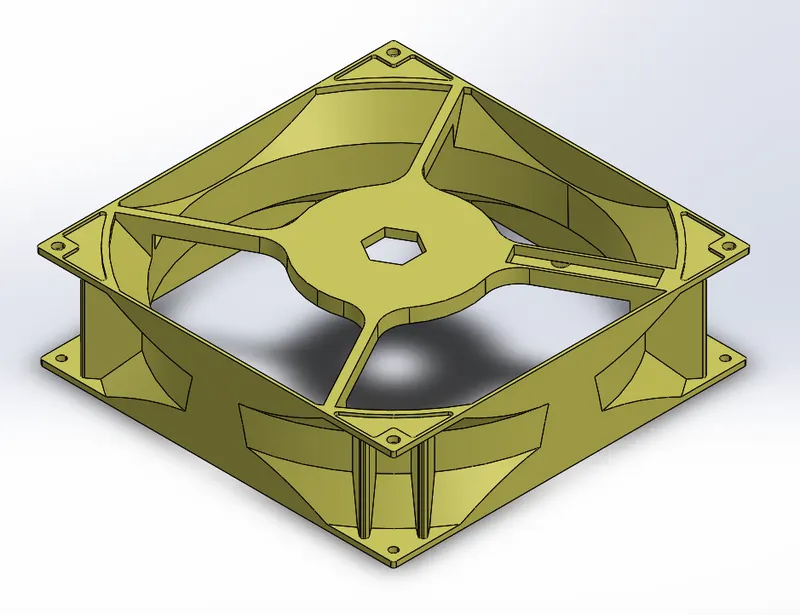
The Given Body
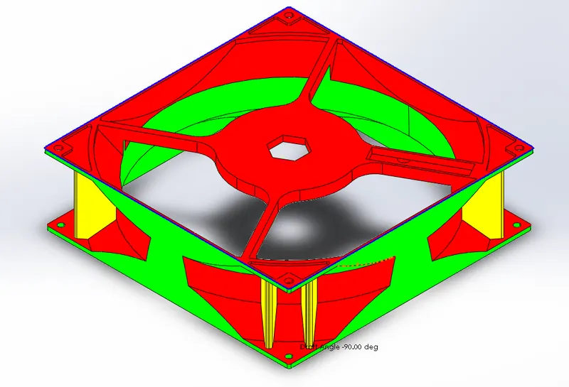
Draft Analysis of the body at 0.5deg
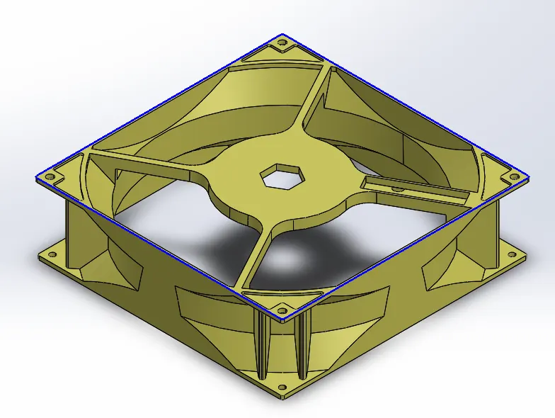
Parting Line
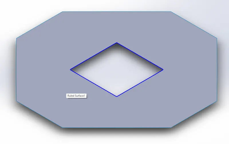
Parting Suface
Core Surface
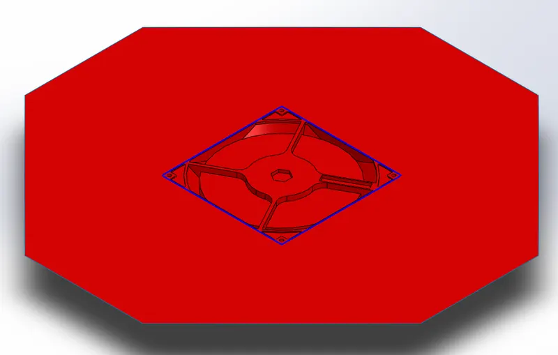
Cavity Surface
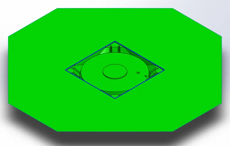
Portions showing slider requirments
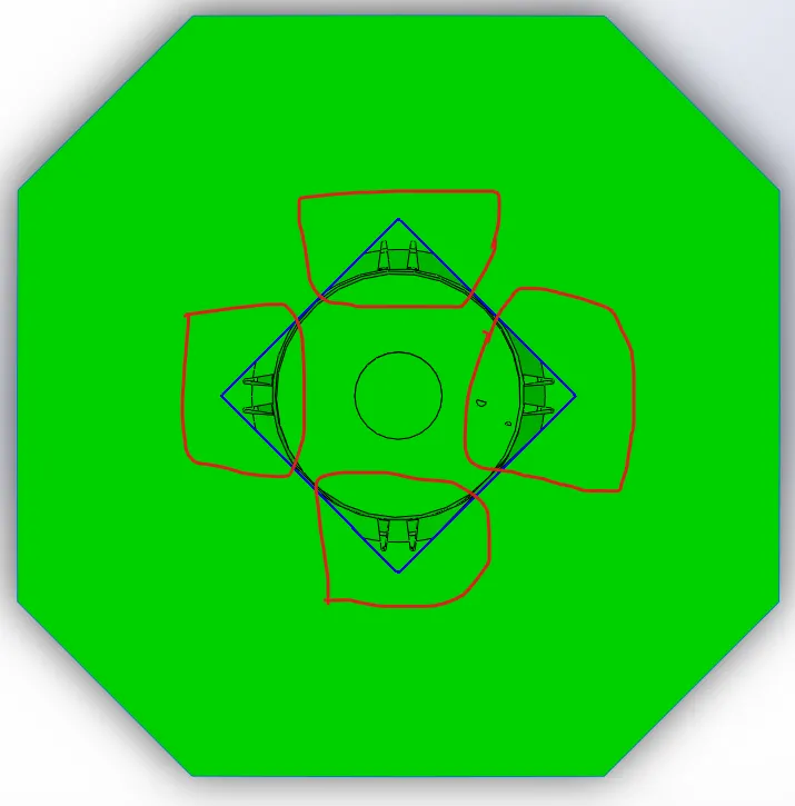 the encircled parts shows the portions on the body that requires a sliders to be manufactured.
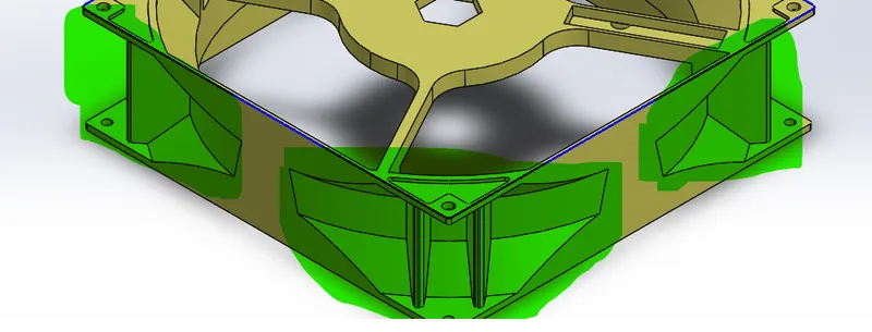
the highlighted features shows the features to be manufactured using sliders
Final Core Block
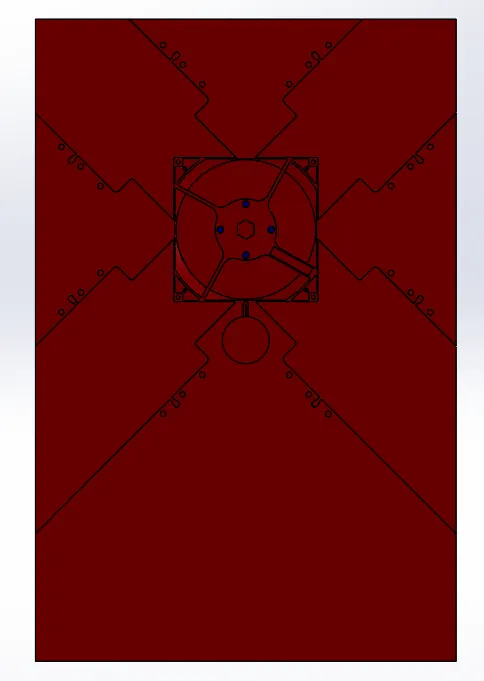
Final Cavity Block
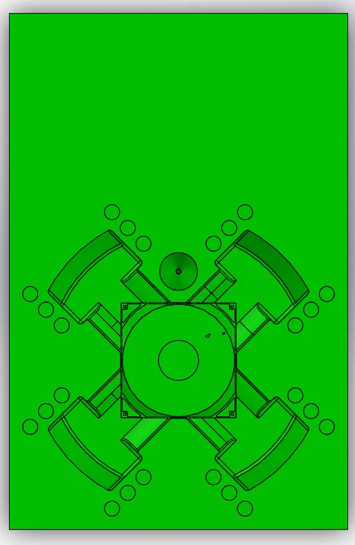
Sliders
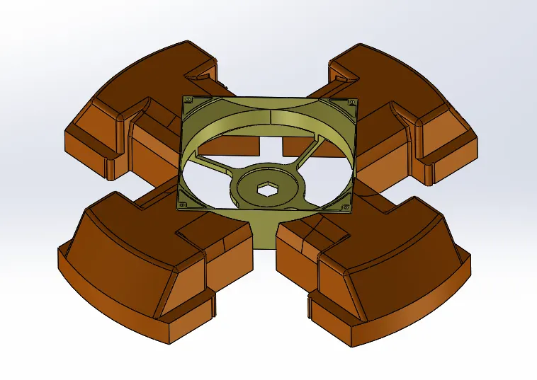
The above picture shows the positions of sliders
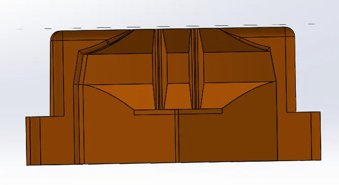
The above pictrure shows the shape of the feature be manufactured.
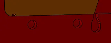
The above picture shows the grooves for the slider locking mechanism
Core block with sliders and washers
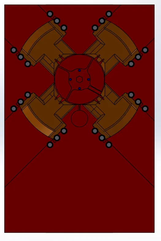
Ejector pins and Ejector plate
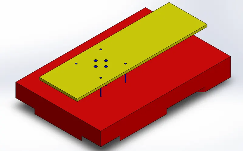
the above picture shows the ejector pin heads and the ejector plate
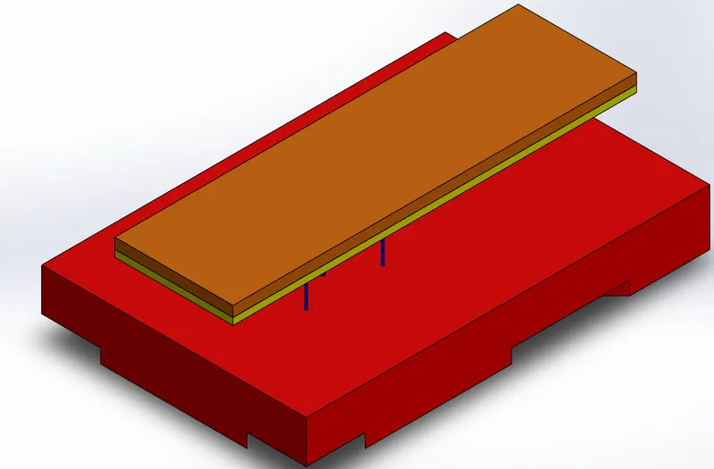
Sprue in the cavity block
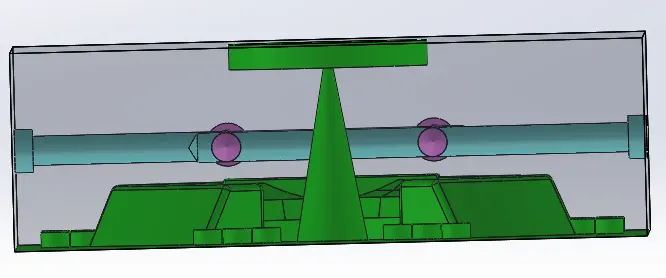
Entry Dia 5.8mm
Exit Dia 42.55 mm
Sprue Catcher runner and Gate in the core block
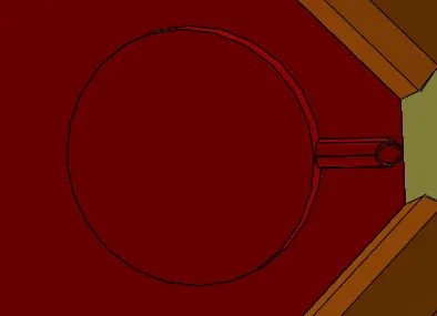
Runner typ-Trapizoidal Runner
Gate typ-Edge Gate
Cooling Chanels
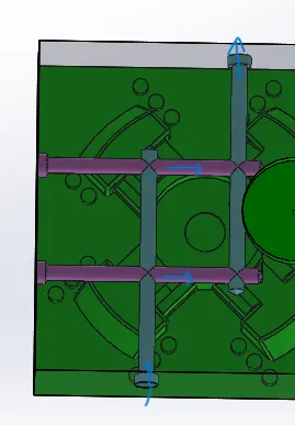 This perticular cooling chanel system shows the parallel cooling system.
Final sectional View
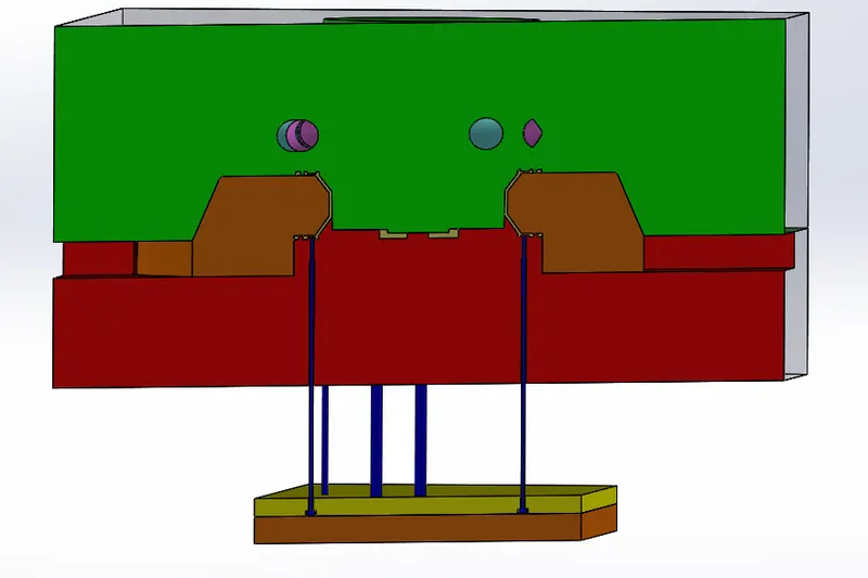
The standard that are followed to prepare the mold
- All the dimensions that are provided for the mold making are in accordance to the OEM standards.
- All the core and the cavity features are in RED and GREEN colour respectively as for the standards
- The mold design is done for scaled size of 0.6% to counter the srinkage of ABS
- For this perticular project the ejector pins are of two sizes with flat heads that are 3mm & 6mm.