Project 2
AIM:
To calculate the wave-current forces, centrifugal forces, wave forces, snow loads, Temperature loads, Barge impact loads for the given bridge structures.
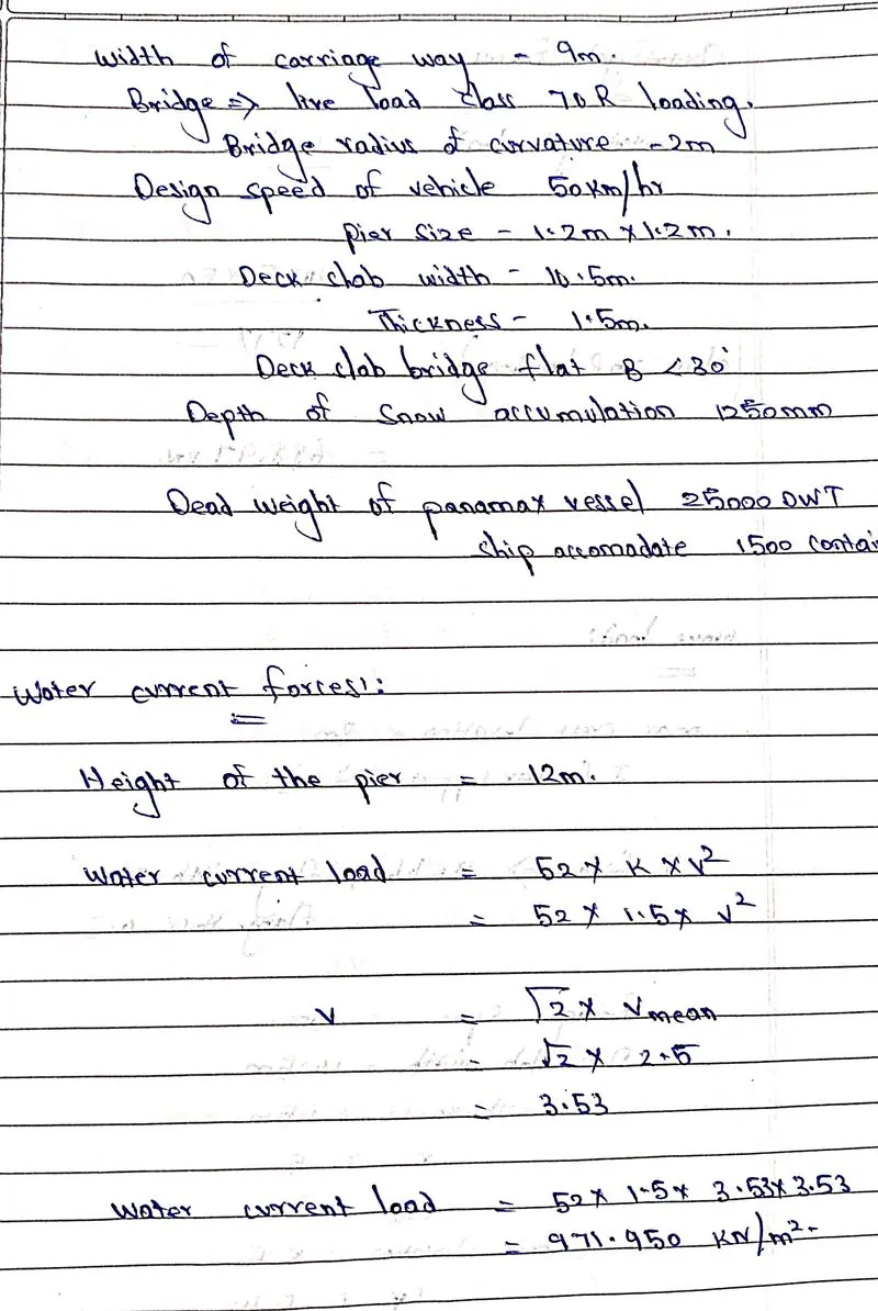
water current loads: The ocean current is driven by density and temperature gradients, The major ocean currents are
- 1. North equatorial currents,
- 2. Atlantic currents,
- 3. North Pacific currents.
- 4. south Indian currents.
water current loads are influenced by topography and ocean basins, To calculate the water current load
- P= 52 * K * V * V
- P= pressure intensity due to the water current.
- v maximum velocity of water current.
- where K is constant, varies accordingly with shape.
- The maximum velocity v = 1. 414 * V mean.
Centrifugal force:
- The centrifugal force is an outward pushing force that exerts a load on structural elements of the bridge.
- The centrifugal force which tends to move the vehicle out of the track causes a collision.
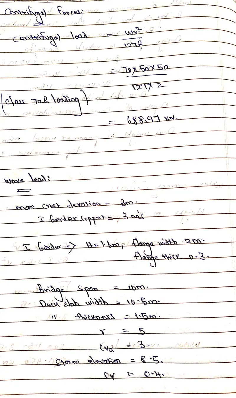
- C = w*v*v / 127 R
- c is point load or udl.
- w= live load of the vehicle class 70 R loading.
- v= design speed of the vehicle in km/hr.
- R is the radius of curvature.
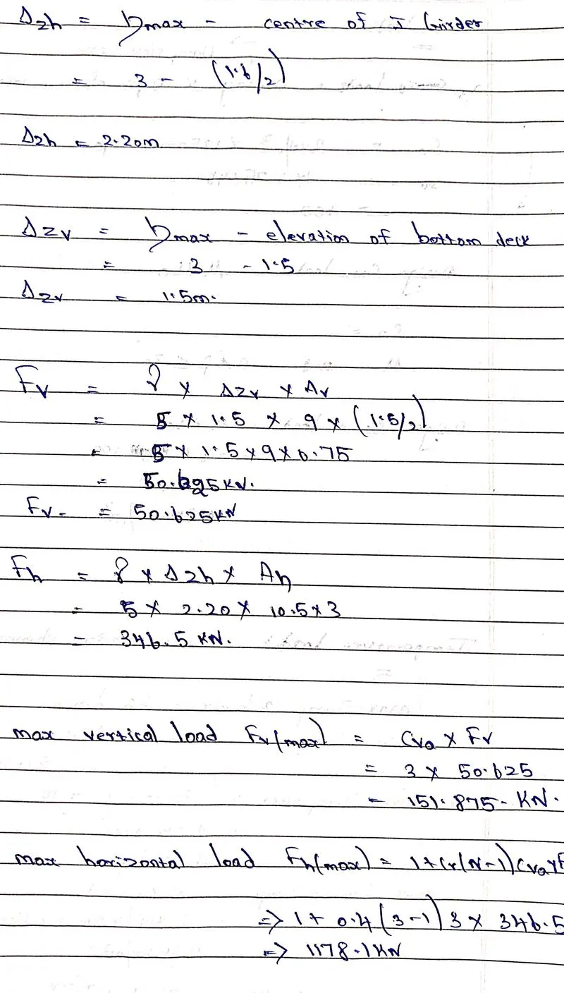
wave forces:
- wave load is caused due to the disturbance of the water surface.
- The disturbances are wind, boat, ship and other underwater landslides due to the earthquake.
- Based on the intensity of the wind, the wave generates a force on the bridge substructure like piers and abutments. These wave loads will cause damages to the structure and have a tendency to uplift the superstructure.
- wave loads have two components
1. The crust - The highest point of the wave.
2. The trough- The lowest point of the wave.
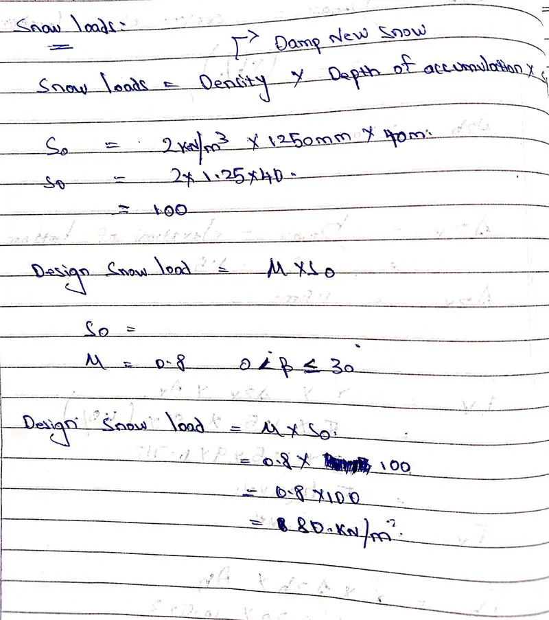
snow loads:
- snow loads are more common in regions where snowfall occurs and regions where colder climate prevails.
- snow load is calculated as per IS 875 part four and also loads are applied as per IRC 6
- The minimum load considered should be 900kg/m3 as per clause 224 IRC 6.
- The design snow load S = μ * s0.
- The density of snow load varies according to its settlement over structure.
- Based on the slope condition the snow load classified into
>> Positive roof slope.
>> Negative roof slope.
>> Multilevel roof slope.
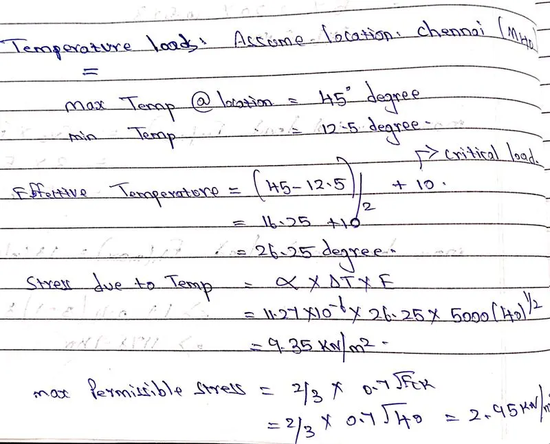
Temperature loads:
- Daily and seasonal fluctuations in shades of temperature by solar radiation cause temperature loads.
- The variation of maximum and minimum temperature due to seasonal changes causes temperature load on the bridge.
- This load causes temperature restraint which causes thermal expansions or contraction at joints, which accelerates material degradation and increases stress in the structure.
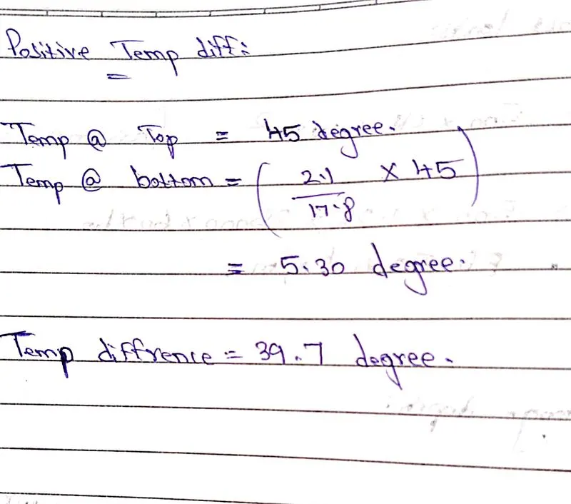
- The difference of temperature in the top and bottom surface of the superstructure needs to be applied as load in staad pro for analyzing the structure.
- IS 875 part five deals with temperature load.
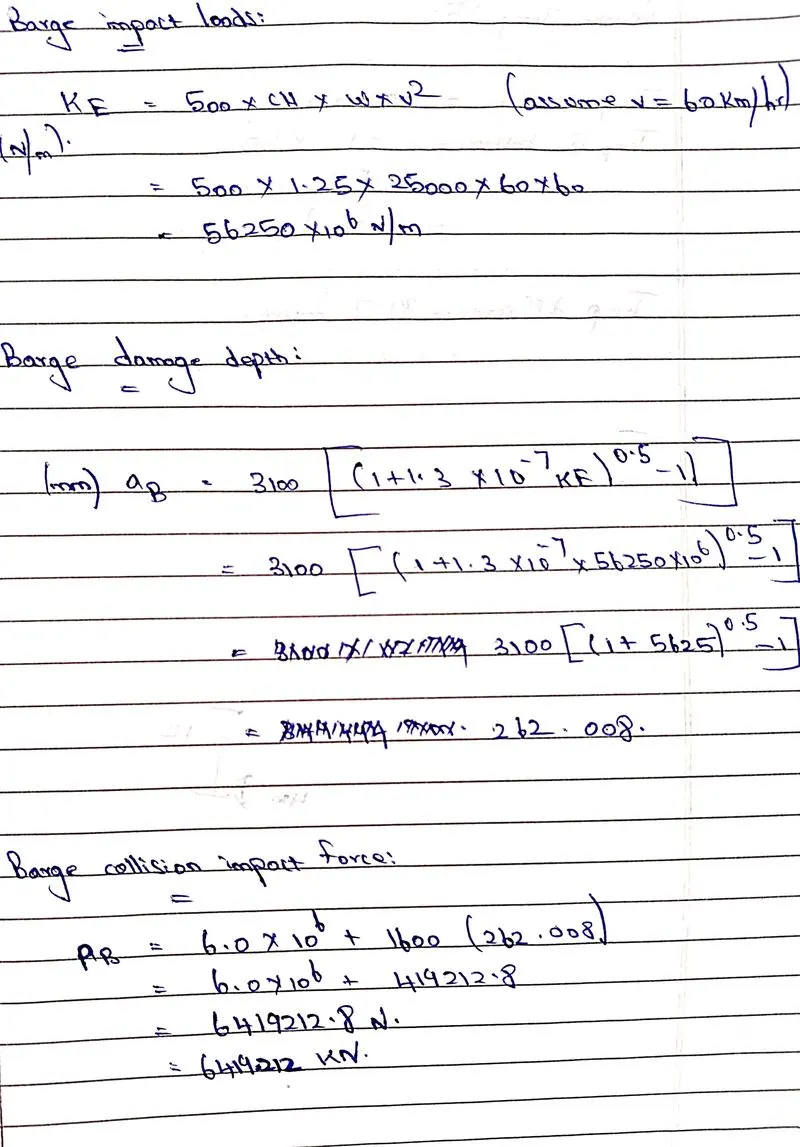
Barge impact loads:
- Barge refers to the ships or vessels crossing the bridges constructed in rivers, canals, sea causes collision on the bridge structure.
- IRC 6 2017 gives the details for barge impact load
- Barge collision energy is given by KE = 500 * ch * w * v2
- CH is a hydrodynamic coefficient.
- W is barge displacement is tonnage.
- V is barge impact speed.
PROCEDURE :
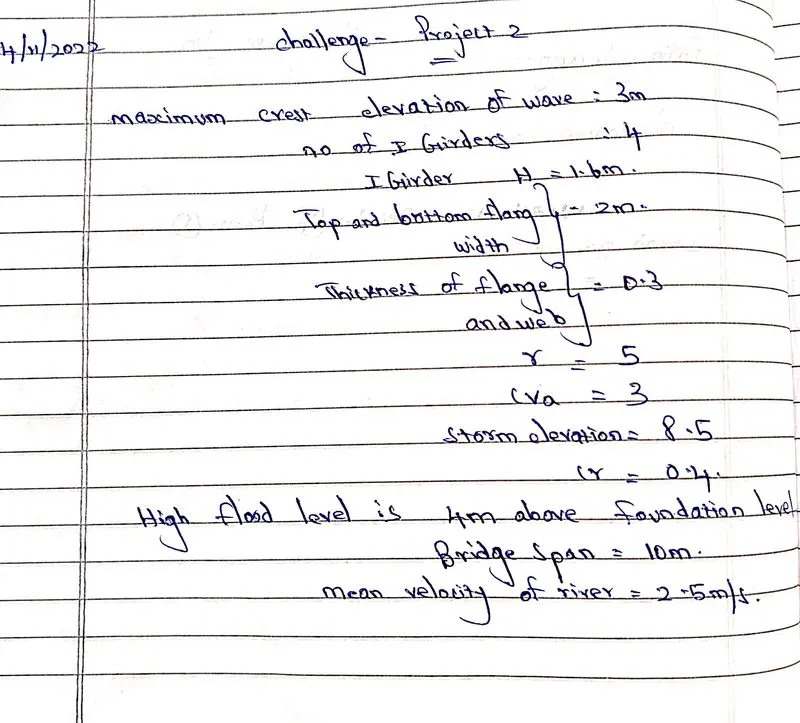
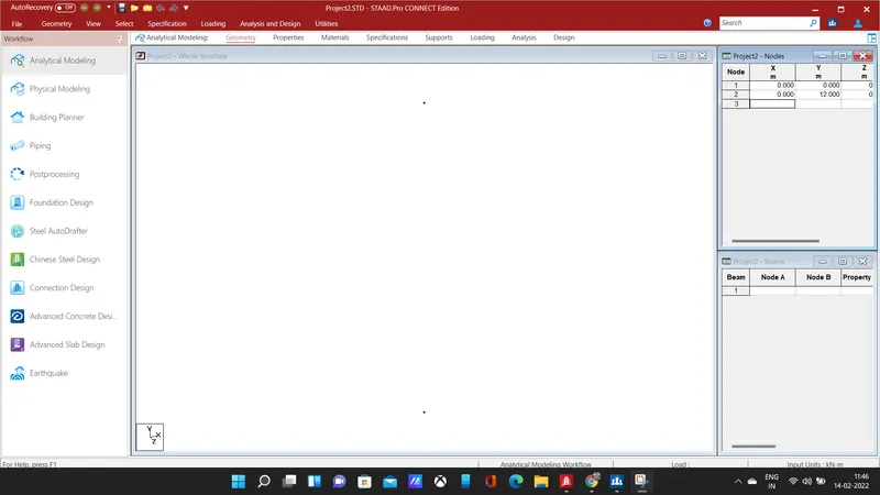
- Enter the coordinates for the piers (0,0,0) and (0,12,0), the 12m is the total height of the pier, connect the pier by using add beam command.
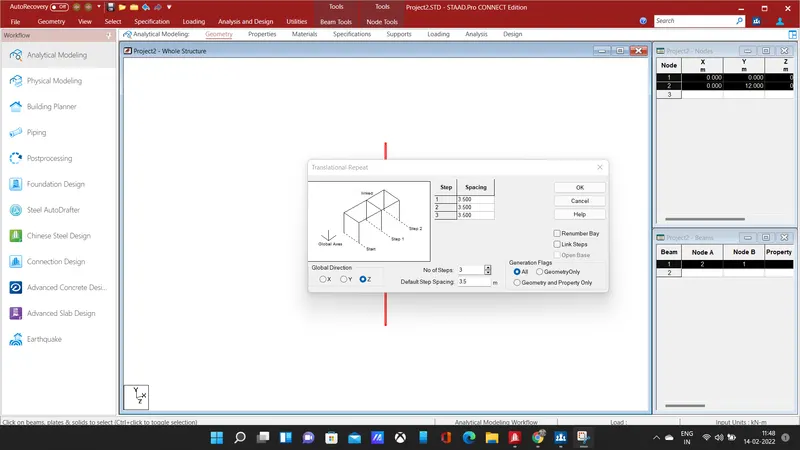
- select the beam and copy the beam using translational repeat in z-direction for 3 steps at a spacing of 3.5m and connect the piers by adding beam.
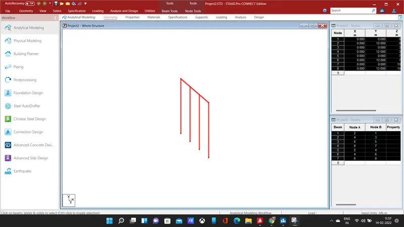
- The above shows the bridge along its width, there are four piers each spaced at a distance of 3.5m
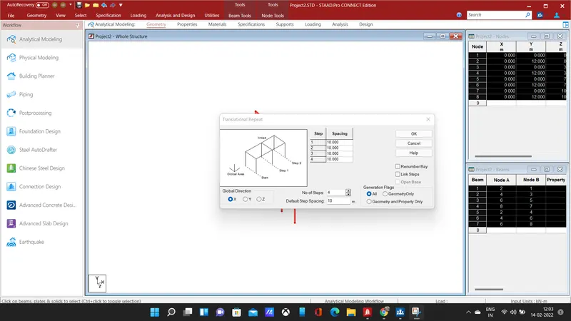
- select the piers and copy them in x-direction using translational repeat command at a spacing of 10m for 4 steps.
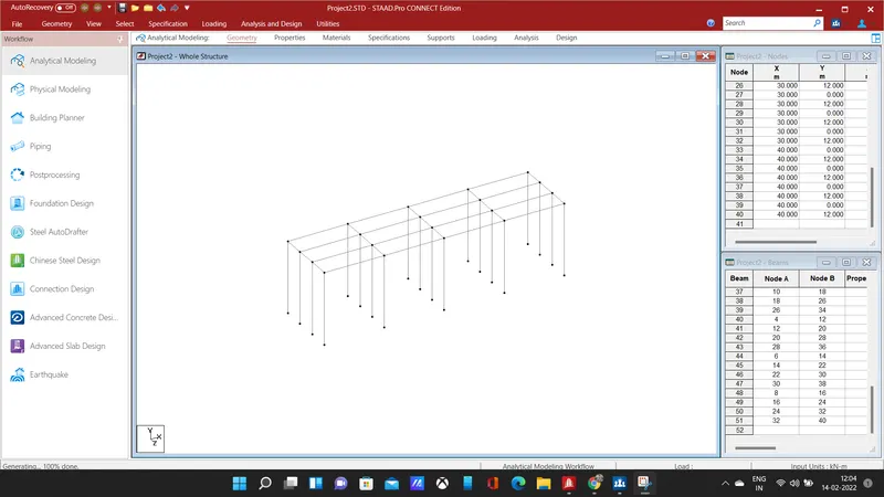
- connect the piers by adding longitudinal beams and cross beams, hence the bridge of 40m span has been modelled, next step is to assign properties to the members and to add support.
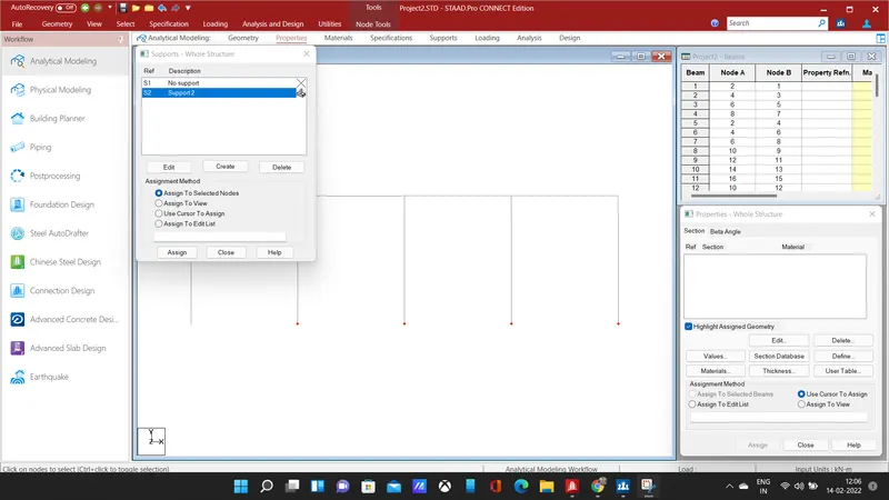
- Add fixed support, select the nodes of each pier and assign the support to the selected nodes of the piers.
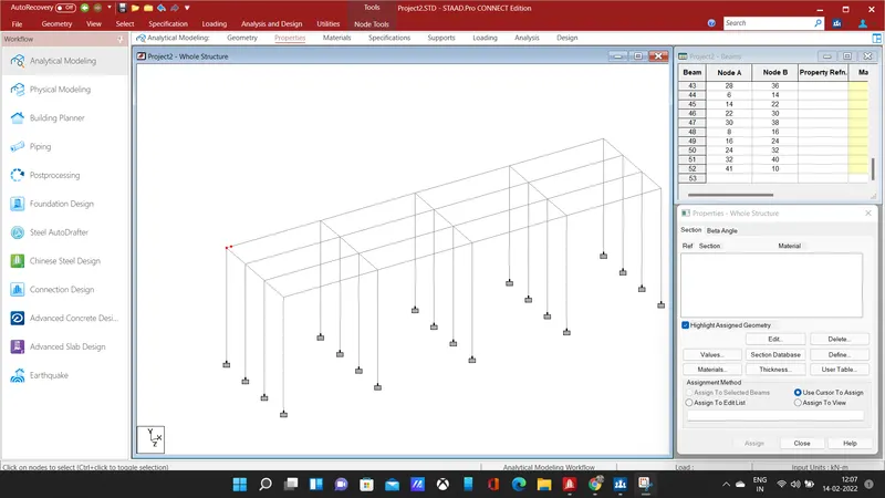
- selected the corner nodes of the bridge and copy them in the x and z direction using the repeat command to add a plate.
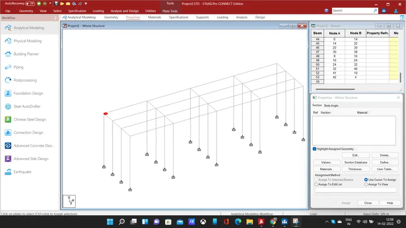
- add a plate by connecting the four nodes using add plate command,we need to copy the plates in x and y direction to form the deck slab.
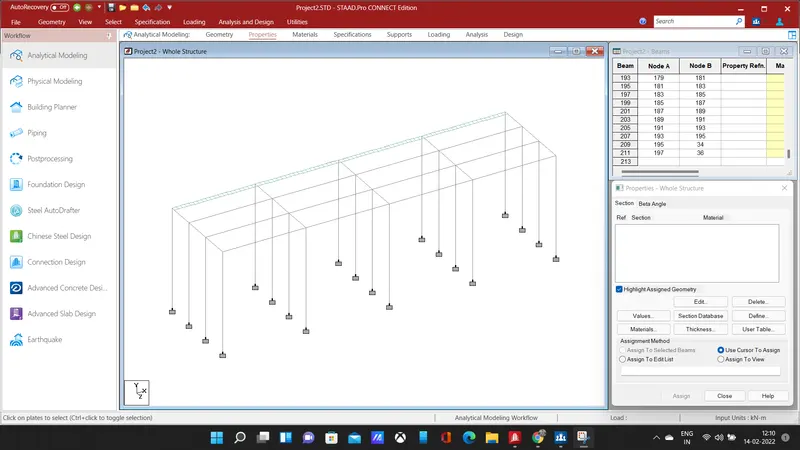
- select the plates, copy them in the x-direction using translational repeat command for 79 steps at 0.5m spacing.
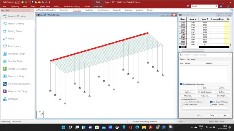
- select the copied plates and copy them in z-direction for 20 steps at a spacing of 0.5m, hence the deck slab has been formed.
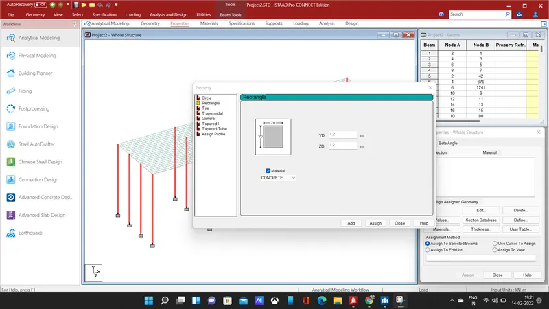
- Next, we need to add properties to each member, select the piers and define them with a rectangular section of 1.5 * 1.5 m and assign the property to selected piers.
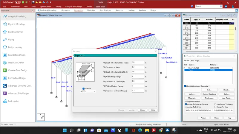
- Add a I section for the given dimensions and select the longitudinal beam to assign the I section properties.
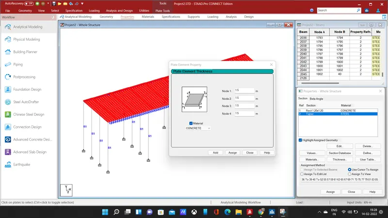
- Add plate thickness of 1.5m and select the entire deck to assign the selected plate thickness.
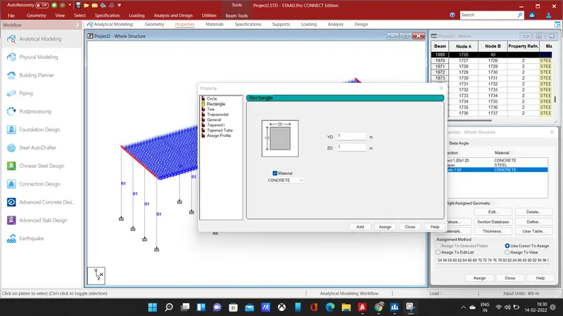
- Add a rectangular cross-section of 1m * 1m, select the cross beams to assign the properties.
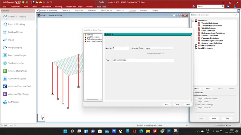
- The next step is to give loading to the bridge structure, add load case details and give title as water current loads.
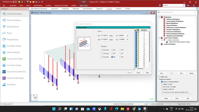
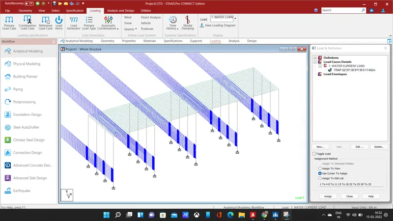
- Add member load and enter the calculated load, select the pier and apply the load in the global z-direction.
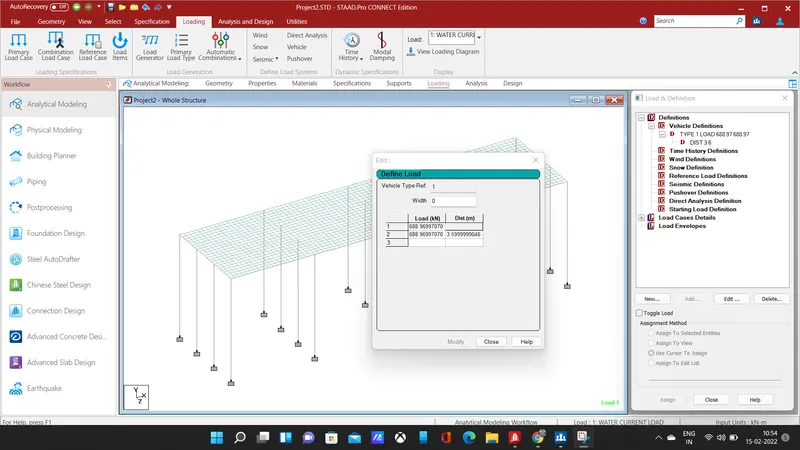
- The next step is to give centrifugal loading add vehicular definitions and enter the calculated loading at a distance of 3.6 in define load section, after the enter the coordinates for placing of load.
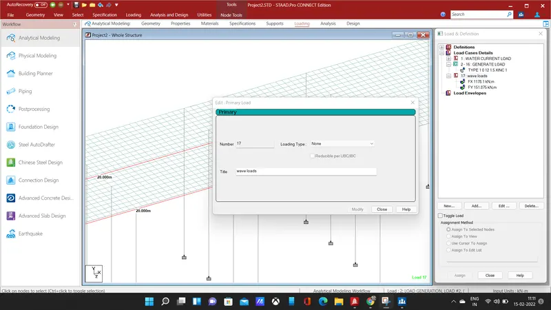
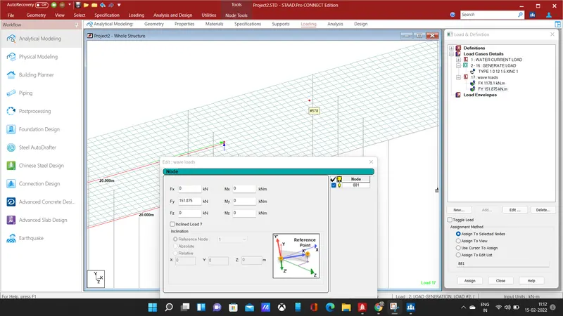
- Next, we need to give wave loads, add a new load case and give title as wave loads, the load needs to be applied as nodal loads at the centre, apply the calculated load fx and fy in respective directions.
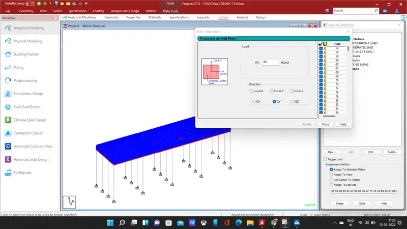
- select the entire deck slab and apply the snow loads as plate loads in the negative global y direction.
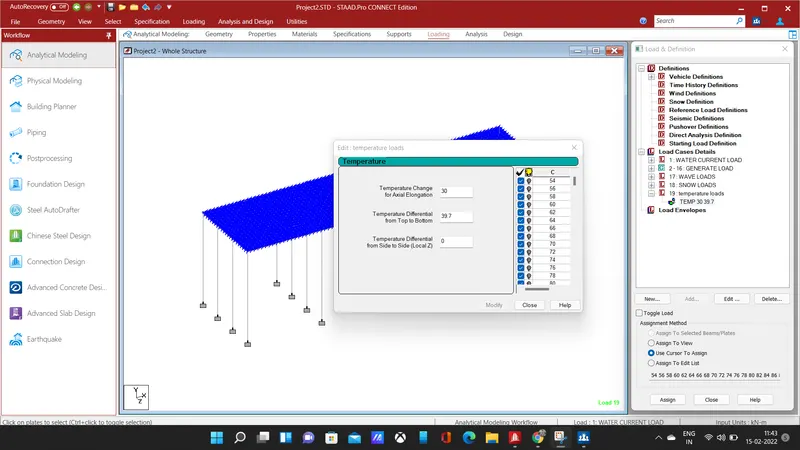
- Assume the zone as Chennai and m40 as the grade of concrete for temperature loading,add a load case details and give the temperature definitions then select the plate and apply the load.
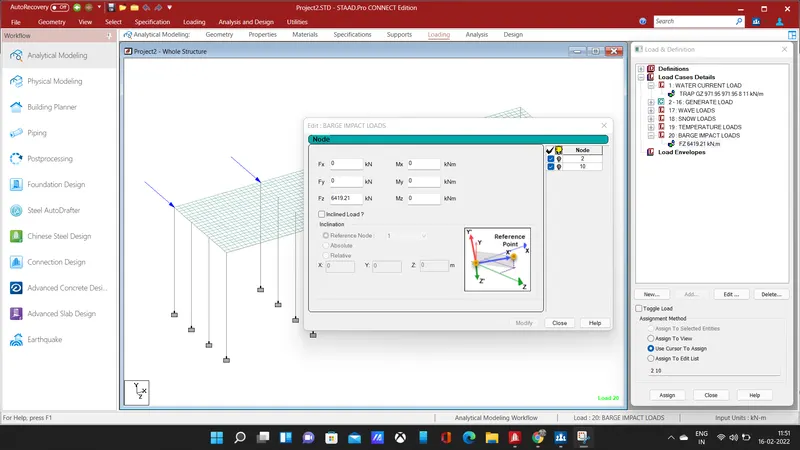
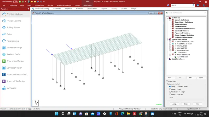
- The next step is to give barge impact loading, we need to apply the load as nodal loads, select the node and apply the loads in z direction for the calculate barge load values.
RESULT:
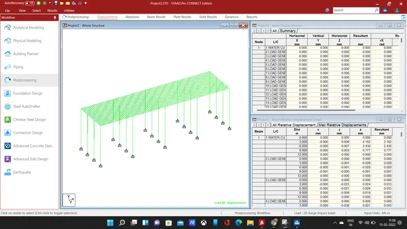
- The above image is displacement for the applied loadings.
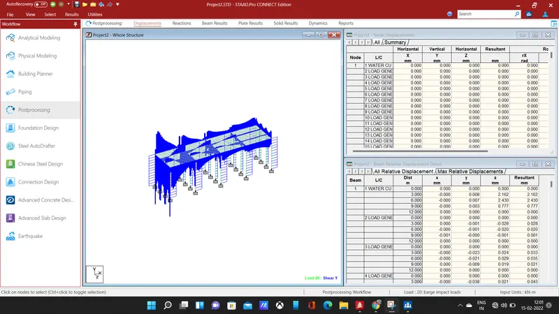
- The shear diagram in the y-direction is shown above, for all the loading.
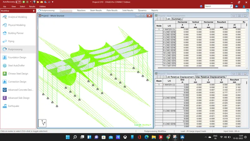
- The bending moment diagram in y-direction for the complete loading is shown above.
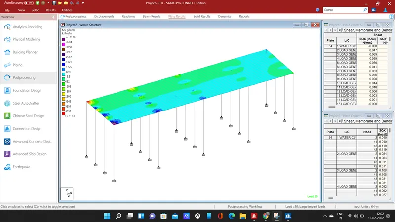
- Select all the plates and click on the plate stress and choose stress type as MX local, the maximum and minimum values of plate stress value will be shown as contour image.
- The bridge is designed for a given specification and calculated load has been applied over the modelled bridge.