Project 2
AIM
Designing the wiring harness for the specified car body and creating a flattened view design in CATIA V5. By putting into practice the industry best practices covered in this course, such as the application of all packaging regulations in design. Apply protective coverings when necessary.
OBJECTIVE
- Define all the mechanical connectors electrically and save it in the Catalogue.
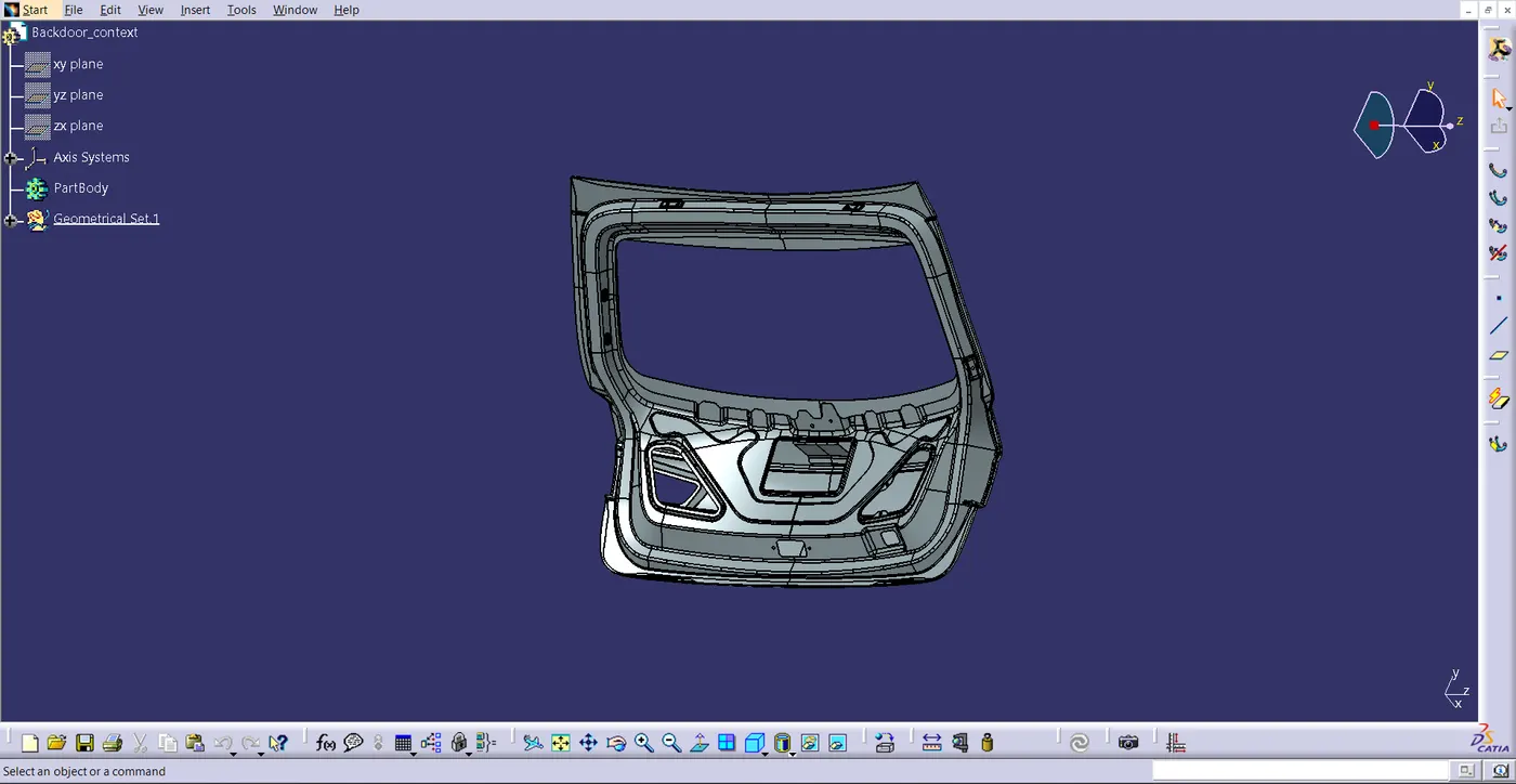
- Place all of the connectors in their appropriate locations on the tailgate or backdoor 3D CAD model that has been provided.
- Place the Fir Tree clips and P-Clamps in the proper places as per the package instructions.
- Use all mounting hardware and electrically defined connectors to create the wiring harness routing.
- Create branching points where appropriate to produce subbranches and link to various connections within the geometrical bundle.
- When required, wear protective gear.
- Build the bundle's wire harness flattening.
- Flatten the wiring harness and use the drafting workstation to create a drawing sheet.
INTRODUCTION
The trunk, often known as the boot, is an automobile's main cargo or storage room. Usually, it is a hatch located at the back of the vehicle. It is sometimes referred to as a tailgate. These doors can be operated manually or with electricity. Most luxury cars have doors that are operated by electricity. It is important in situations involving rear collisions. Therefore, we must follow crash standards in our design. Our vehicle is rated by the Institute of Highway Safety using a test that they created after looking into multiple collisions. As a result, the grade is determined by the inner and outer panel connection technique, flanges, embosses, material used, and further trunk design elements. The back door protects the occupants and their possessions from harm, among other things. Along with other components, it includes the wiper motor and tail lamp assembly. Its windshield glass enhances visibility from the rear. It is equipped with parking sensors and a rear-view camera.
PACKAGING RULES
- The wiring harness ought to be designed so that access and assembly are simple.
- When designing the wire harness, ease of manufacture, installation, removal, and maintenance must be considered.
- connection Avoid wearing a harness in areas with sharp edges, corners, etc.
- Avoid routing and cutting the harness in regions that are difficult to access or blind spots when assembling or servicing the harness.
- If more slack is required, provide it in accordance with the harness bending and surrounding requirements. The envelope dimensions during door opening and shutting must be taken into consideration in order to allow slack if the harness is going through the closures, doors, or tail gates. To prevent having too much slack, check the harness slack requirements with open and close circumstances.
- It is not recommended to route through tiny structural apertures and holes. to reduce handling and chaffing of the wiring harness while it is being installed.
- When designing the wiring harness in the CAD environment, it is important to ensure that there are no instances of fouling. To prevent fouling, additional mounting tools like clamps and clips might be employed.
- It is advisable to use a rubber grommet when the harness is going through sheet metal panels. For instance, a firewall, a tail gate, a passage to door, etc.
- There should be more than 50mm of branch length.
- There should be a minimum of 25mm between the clip and the branch point.
- There should be a minimum of 50mm separating the two branch points.
- The wiring harness clips and clamps should be readily accessible in the market to prevent additional expenses for specialized mounting solutions.
PROCEDURE
Step 1
- Download the necessary connections' CAD data and the tailgate CAD data from the provided link.
Step 2
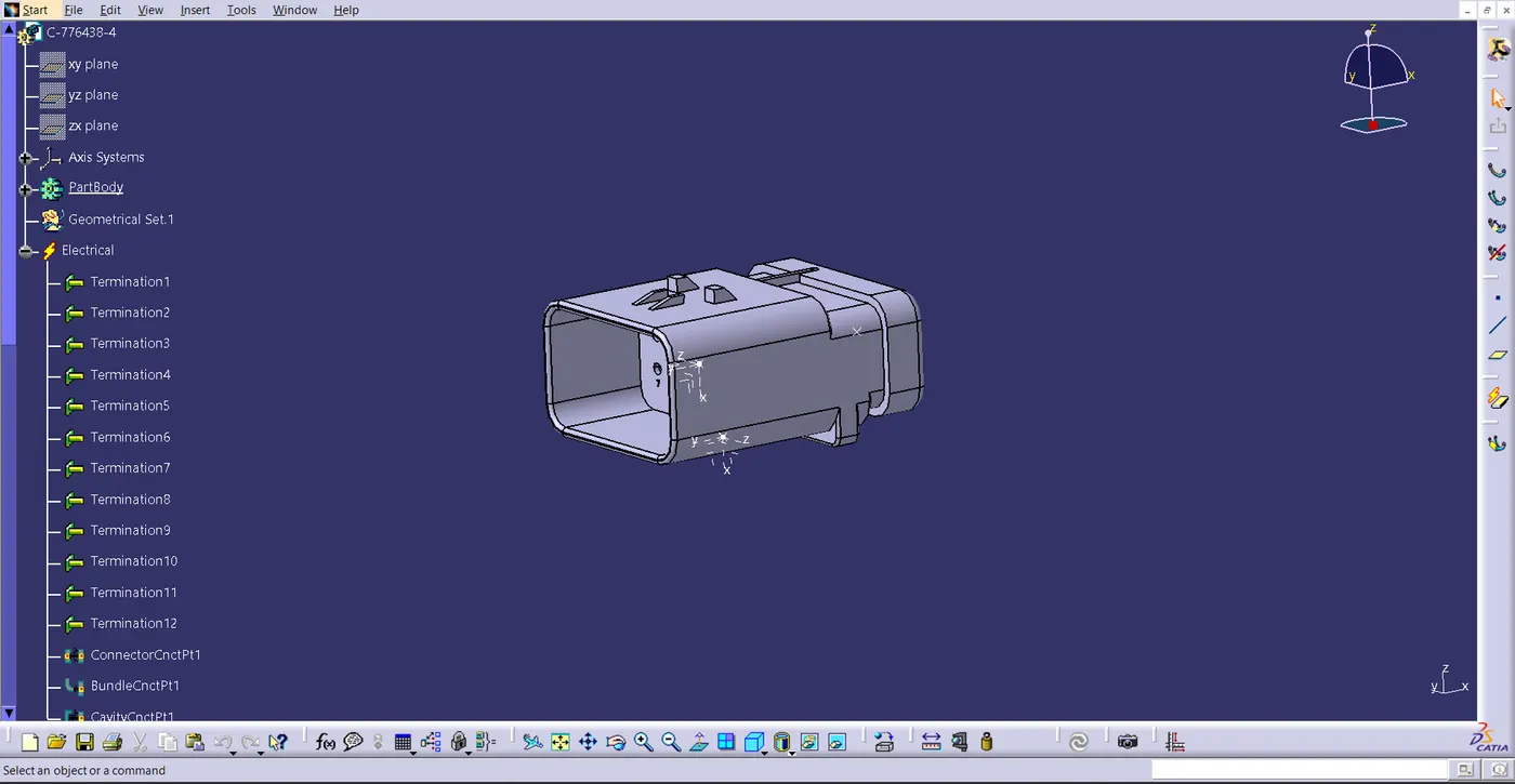
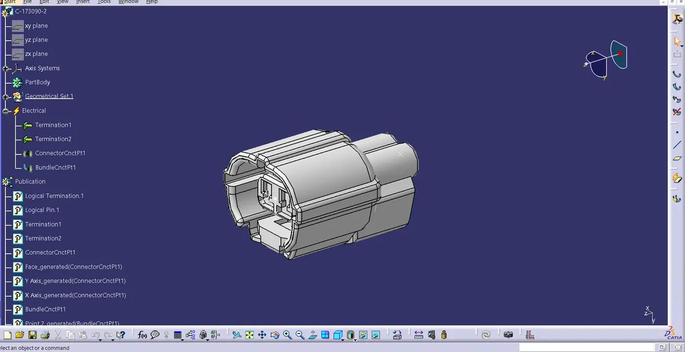
- Download the necessary connectors from the source, then use the electrical component design work bench to convert the mechanical connectors to electrical connections by following the steps listed below.
- Enter the mechanical component workbench and establish the necessary geometric parameters. On the necessary sides of the CAD part, create connector and bundle connection points.
- Establish an axis system on the connector connection point with the Z coordinate, the X coordinate facing the locking mechanism, and the Y coordinate normal to the connector face.
- Create cavity connection point for connectors having the cavity for mounting clips with the developed geometrical parameters.
- Define part as electrical connector.
- Define the connection point for bundles.
- Determine the connector's connection point.
Step 3
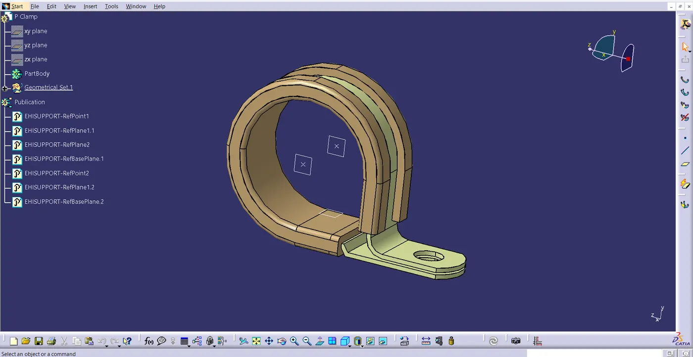
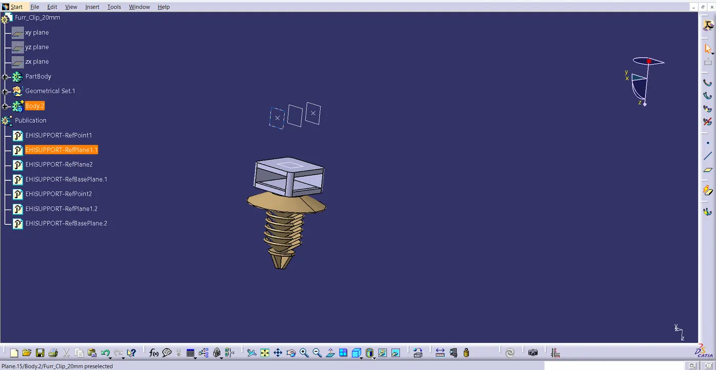
- Download the required clamps and clips.
- Define them electrically.
Step 4
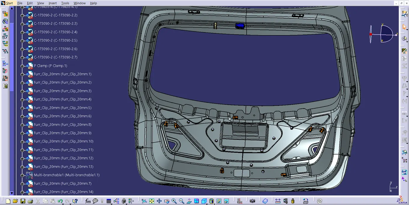
- Context assembly is nothing more than the product file that includes the geometrical bundle of the backdoor harness and the backdoor 3D-CAD data.
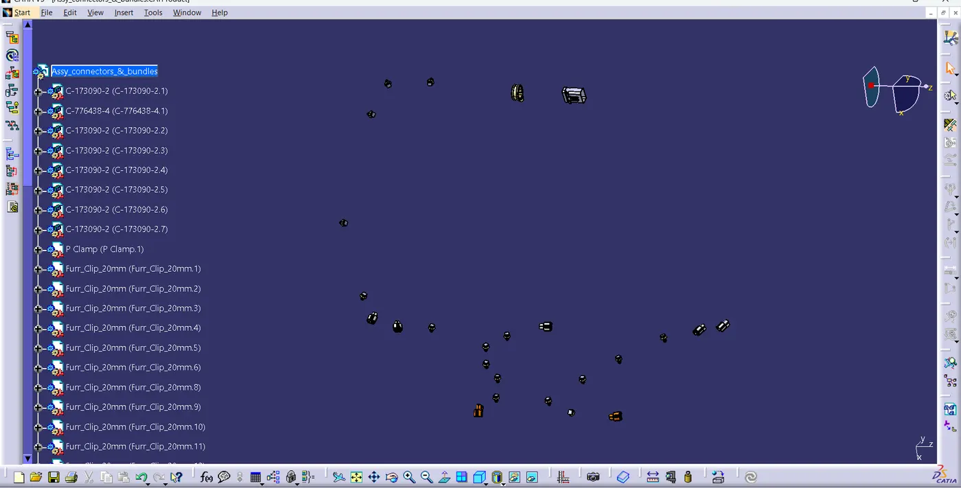
- In this case, the geometrical bundle product includes all of the electrically defined connectors, mounting hardware, clips, and clamps for the assembly. Before adding any parts, the Geometrical bundle product file needs to be electrically specified using the Define Geometrical bundle option.
- Next, we need to switch to the electrical harness assembly workbench.
- Assemble the required parts in the correct position. Connecting all the connectors.
- In addition to assisting with proper routing, adding p-clamps and firtree clips can help shield the harness bundle from mechanical components that are not essential.
Step 5
- Route it by giving route definition.
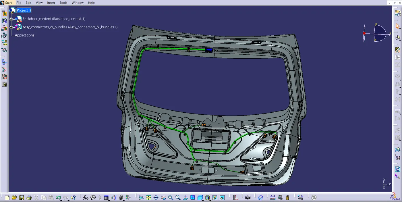
- I created this route by following the packaging rules. Here, I have avoided the disturbance from the mechanical movable parts.
- For example, I didn't route it near the wiper motor and latch mounting because they have more mechanical movements, which can disturb the harness.
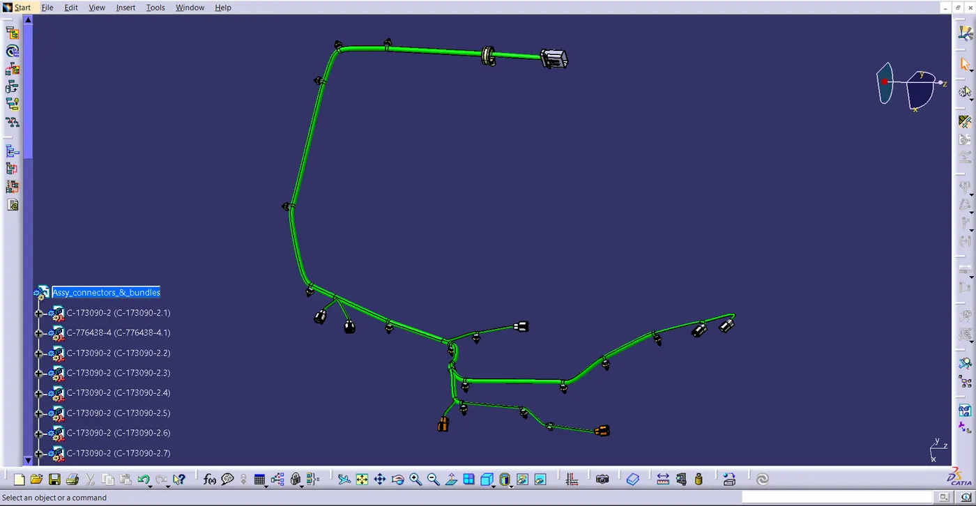
- Then provide protective covering in the required place.
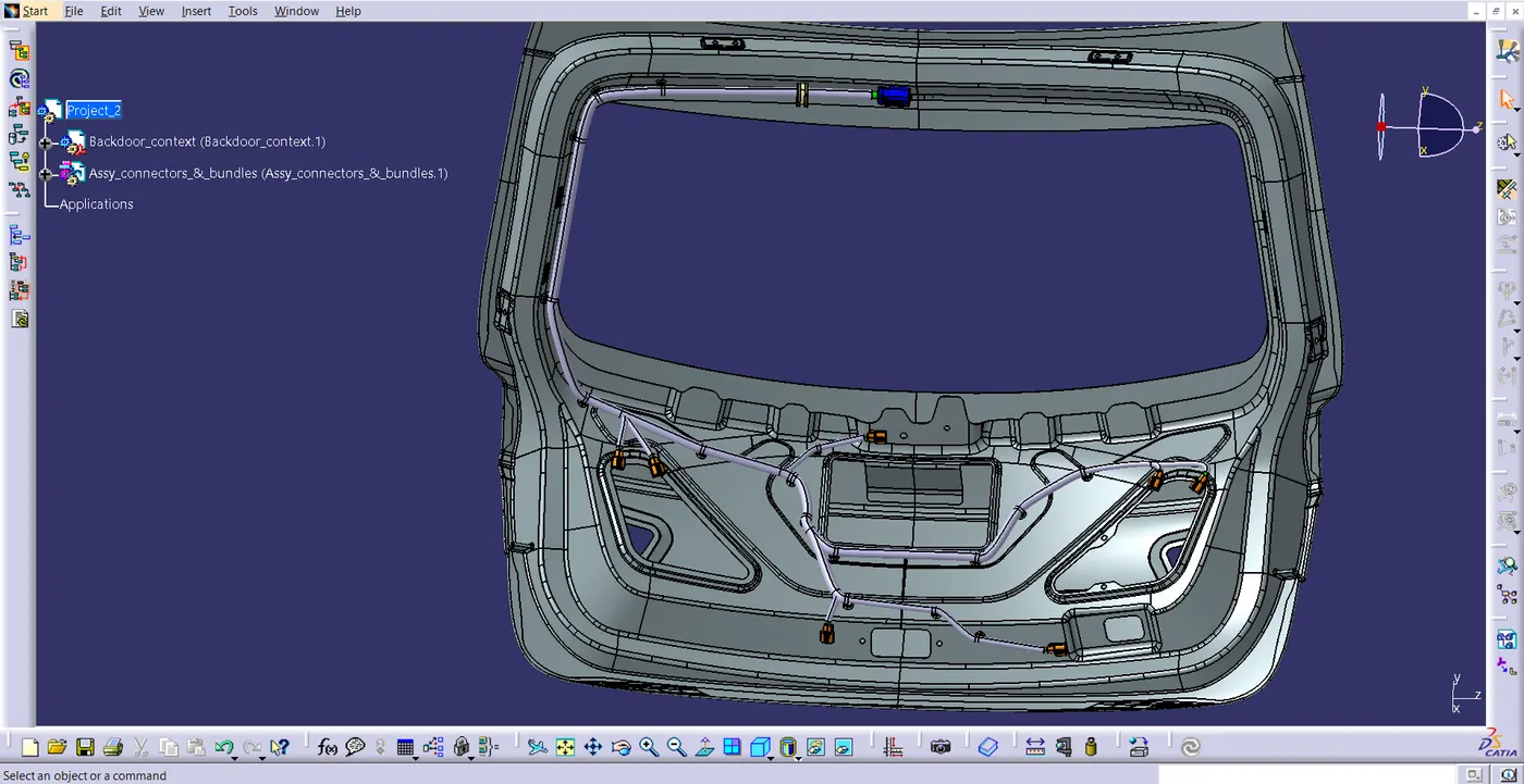
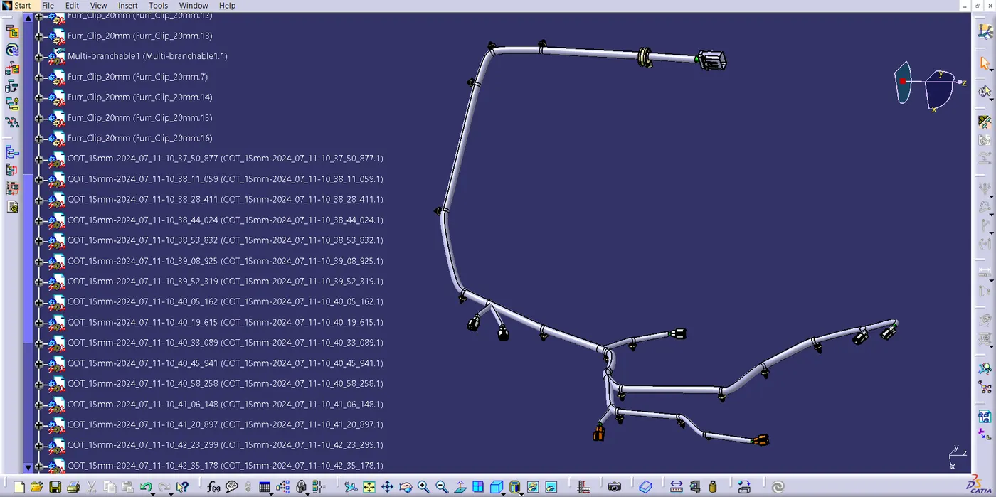
- Using search command in Edit toolbar, check the connectivity
- I have given the snaps of both the False and True attribute criterion respectively.
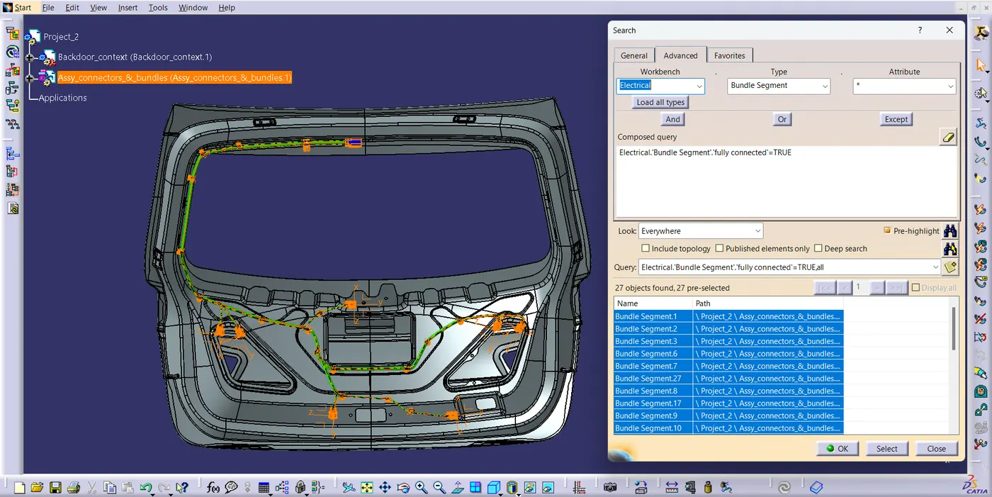
- Open a new product file in the Electrical Harness Flattening workbench after finishing the assembly.
- Define the necessary parameters, such as the plane, flattening orientation, and drawing, using the harness flattening parameter.
- Then, using the Flattening command, Flatten the branches by selecting the branches and the required plane.
- Using the commands like rotate and scale change the it to the required position. Flattening is completed.
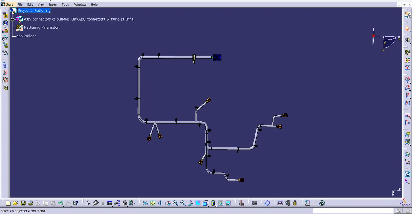
- Using the flattening, 2D drawing is created in drafting workbench.
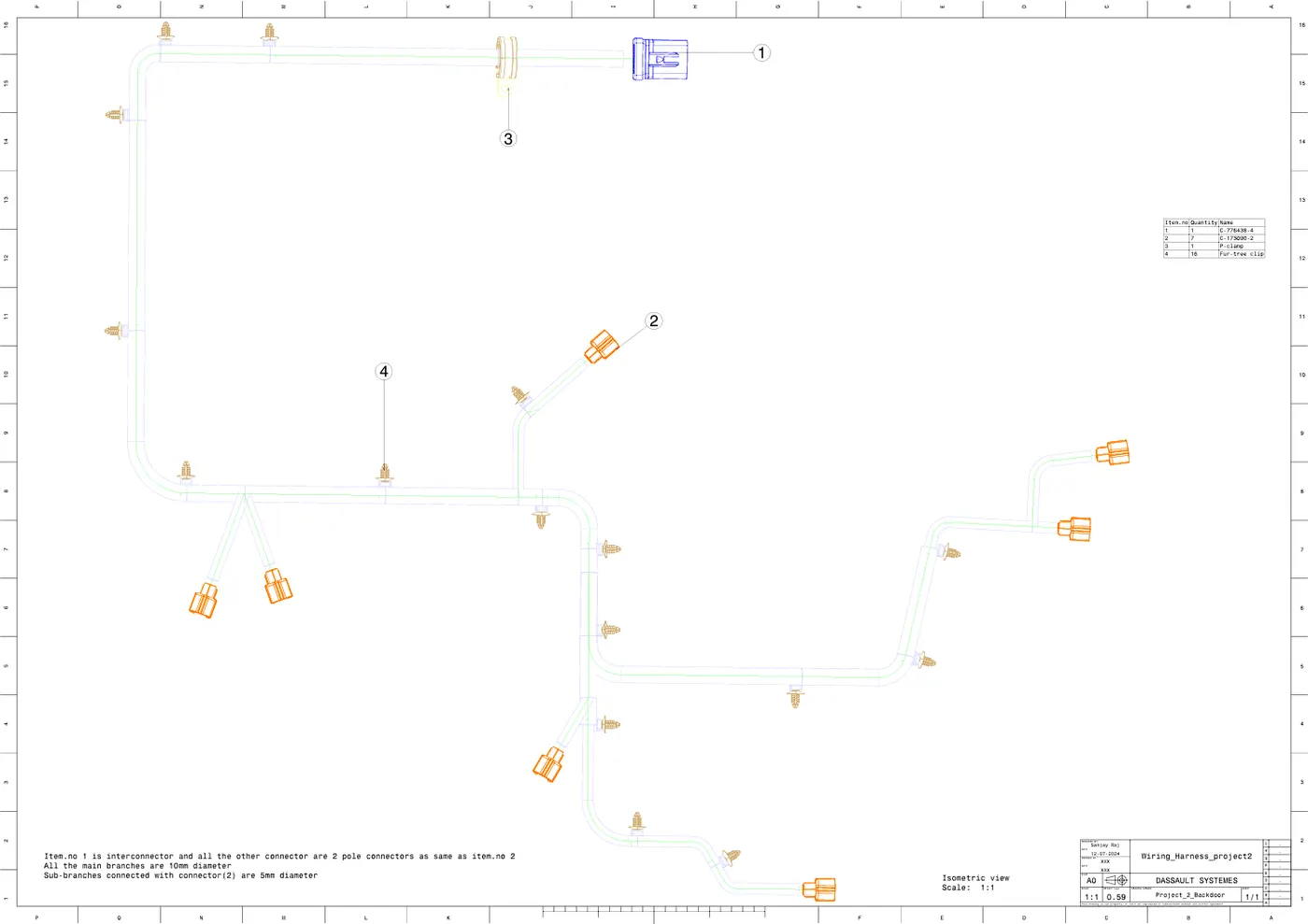
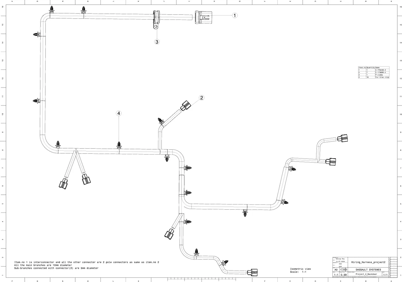
RESULT
We have Designed the wiring harness for the specified tailgate and created a flattened view design in CATIA V5. By putting into practice the industry best practices such as the application of all packaging regulations in design. Applied protective coverings when necessary