Project 2
Conduct the post processing of the results once the analysis is complete. The first task includes, checking the base pressure and settlement beneath the base slab which should be within the limits mentioned in Project-1. If these limits are exceeded then the dimensions need to be increased or decreased so that the base pressure and settlement is under control.
Once the foundation is checked, report the following results in order to carry out the structural design of elements.
- Design Maximum and Minimum Moments in walls and base slabs (Wood Armer Simplified Method)
- Design Maximum and Minimum Shear Stresses in walls and base slabs
- Design Maximum and Minimum Axial Stresses in walls and base slabs
Once the post processing of results is done, carry out structural design of the elements by conducting the following checks
- Construct an excel spreadsheet for calculating the reinforcement requirement in short and long walls and base slabs. For calculating the required design reinforcement, the contribution due to direct tension also needs to be added if significant and it can be calculated by adopting the following method (discussed in Week-3):
M,net = M – T . x
Ast1 = (0.5 fck / fy) {1-√[1-(4.6 B.M./(fck.b.d²))]}
Ast2 = T / 0.87 fy
Total Ast, req = Ast1 + Ast2
M = Design moment obtained from Wood Armer equations
T = Design Tension force in the section (Stress x c/s area of FE element)
x = distance of tension reinforcement from the center line of the section
- Check crack widths of short and long walls and base slab and ensure that it is less than 0.2mm.
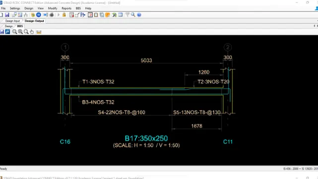
- Draft cross-sectional reinforcement detail (plan and elevation) using a CAD software. If CAD is not available, sketch the details using any drawing tool and clearly indicate all the details.

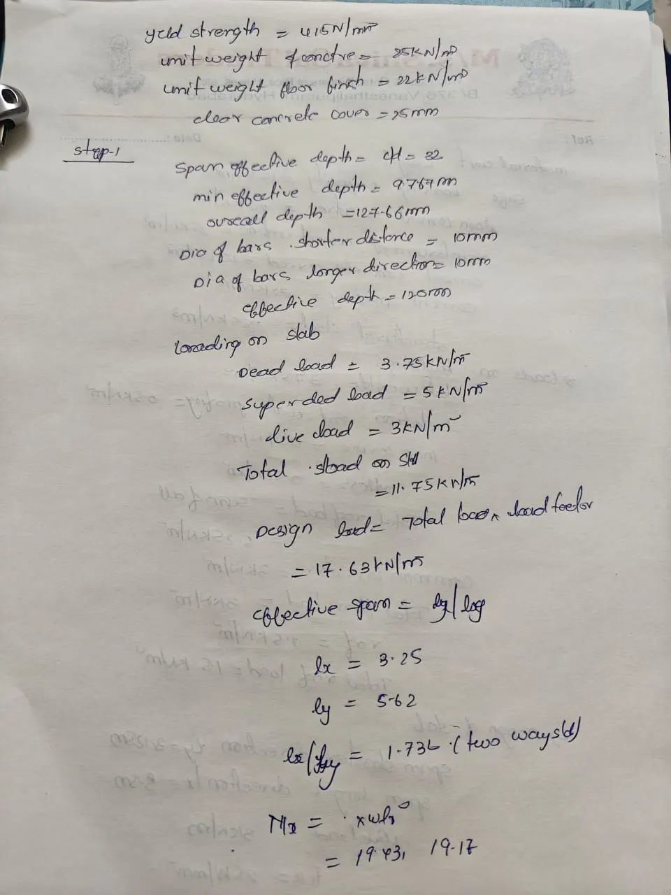
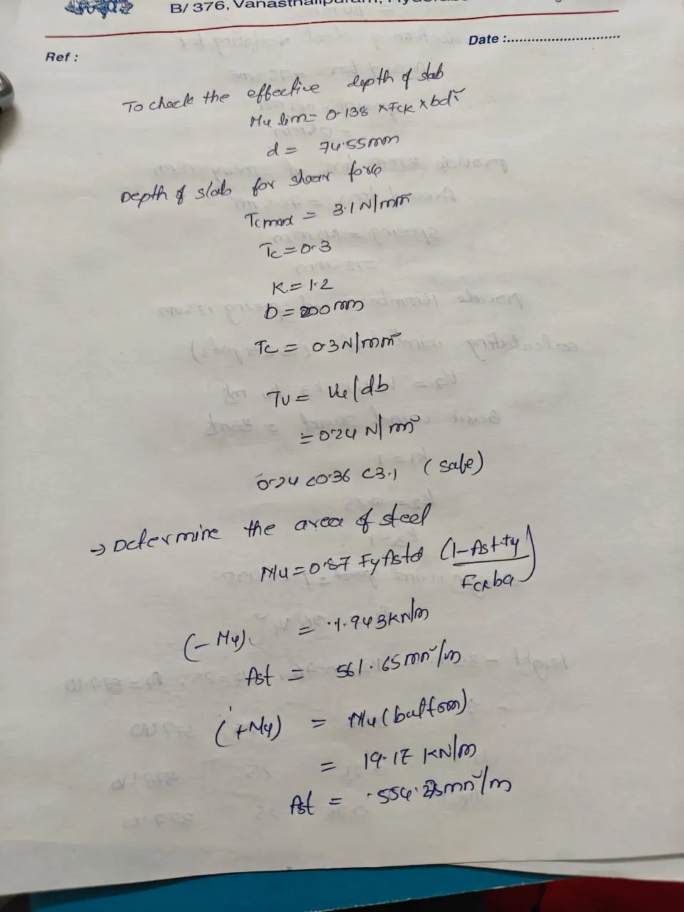
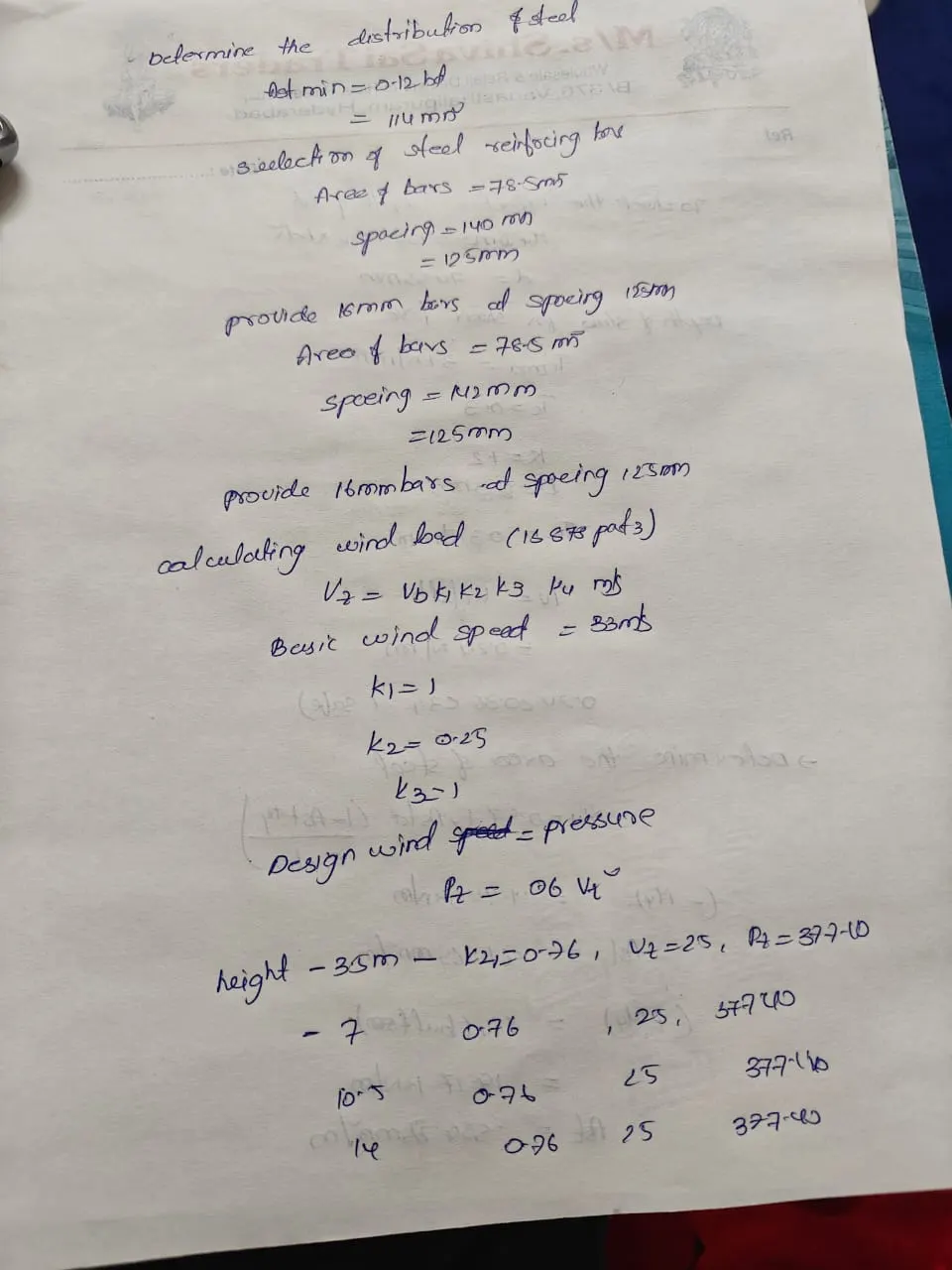
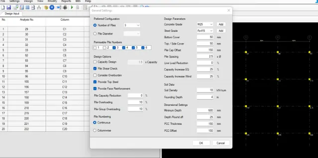
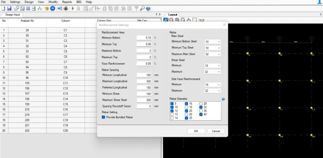
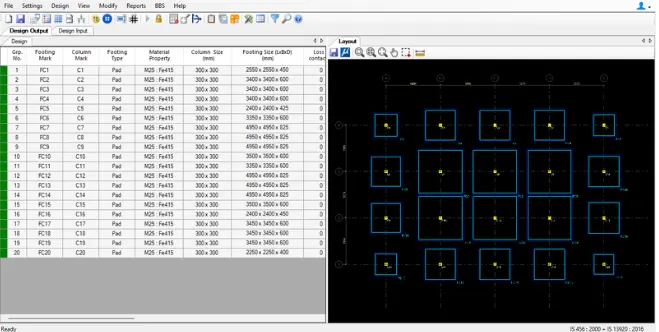
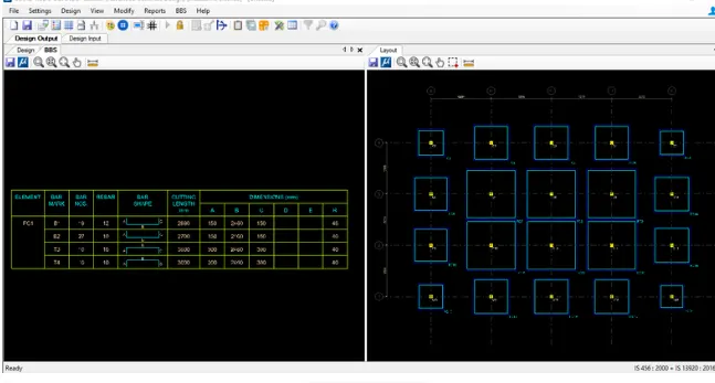
Minimum and maximum flexural reinforcement specified in code for beams or slab elements :-
The minimum reinforcement ratio is the lowest possible quantity of steel that should be embedded in structural concrete elements to prevent premature failure after losing the tensile strength. The minimum reinforcement ratio controls the cracking of concrete members.
The maximum reinforcement ratio is the largest steel area that can be put into concrete members like columns and beam. In a reinforced concrete beam, the provision of extra reinforcement above the maximum reinforcement ratio would not be beneficial since the concrete would get crushed before the full strength of steel is used.
The collapse of a concrete structure is sudden and does not show any signs before failure. The maximum reinforcement ratio ensures concrete members' economy and provides safety against brittle failure of concrete.
Finally, the required reinforcement area of the designed concrete member should not exceed the maximum reinforcement ratio and should be less than the minimum reinforcement ratio. Therefore, the designed member should be checked for this requirement.
Minimum Reinforcement Ratio
The purpose of the minimum reinforcement ratio is to control cracking and prevent sudden failure by equipping the member with adequate ductility after the loss of concrete's tensile strength due to cracking.
Building construction codes such as ACI 318-19, provides minimum reinforcement ratio for different reinforcement concrete members such as beams and columns.
1. Minimum Reinforcement Ratio in Beams
In reinforced concrete beams, if the cracked section's flexural strength is lower than the moment that produced cracking of the previously uncracked section, then the beam would fail upon the formation of the first flexural crack, without showing any distress.
The minimum reinforcement ratio, which can be computed using the equation provided by ACI 318-19, can prevent a concrete beam's premature failure. The minimum reinforcement for beams can be computed using the following expression:

Where:
As,min: minimum area of steel, mm2
fc': compressive strength of concrete, MPa
fy: steel yield stress, MPa
bw: width of web in T-beam, and width of beam in rectangular beam, mm
d: effective depth measured from extreme concrete compression fiber to the center of steel bars, mm