Project 2
Route the Wiring harness on Given car body and Prepare flatten view drawing in CATIA V5. Application of all Packaging rules, Industry best practices studied in this course shall be demonstrated in design. Apply Protection coverings as required.
Solution:-
- All the required Connectors, clips and Backdoor files downloaded.
- We have downloaded all the igs zip files
- Open the CATIA software and convert the files to CAT parts.
- All the Connectors, clips are electricaly defined with the below steps
- Part body is opened and points are created for bundle entry
- Mating points are also created along with the axis definition
- we then switch to electrical part design
- We define the parts as connectors, Mounting Equipments as per the use
- We define the point and bundle entry point.
- Connection connector point is also made.
- This is done for all the connectors and Mounting Equipments.
- Hence it is electricaly defined.
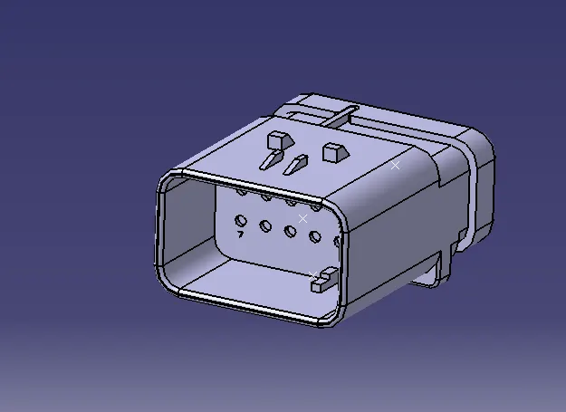
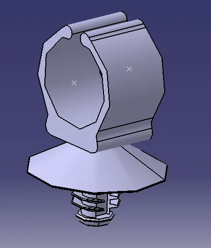
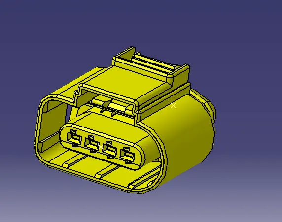
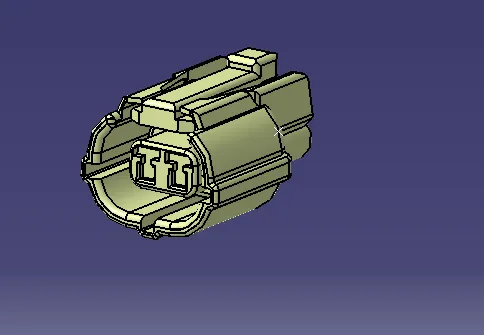
New product is opened and it is named as Back door Harness Context

- Back door is added in the tree by copy paste
- New Product is created and named as Back door Geomentric bundle
- It is defined as geomentric bundle. Note the symbol has changed now.
- We add all the connectors, Mounting equipments here
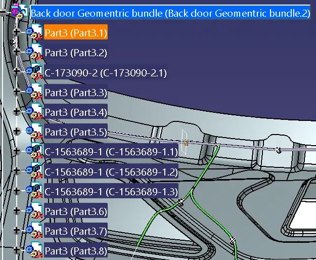
- The components are aligned as per needed.
- We use various commands to rotate and move.
- Multi branchable is added to the geomentrical bundle
- Connectors are routed with the branch bundle by clicking the connectors
- To add sub branches Branch point is created on the main line.
- Then branches are routed to the connectors.
- Tangency are changed to give a good curvature to the harness bundle
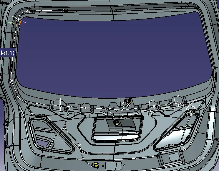
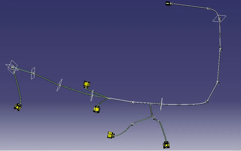
- Protective covering is applied to the branches
- New COT Tube is created and added to our catalog previuosly created
- It is then applied to the branches by clicking the branch and applying the COT tube.
Bundle continuity:
- Bundle continuty is checked by clicking search and electrical and bundle segment and fully connected
- here are the results
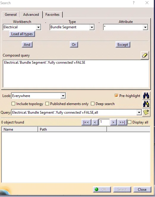
Bundle Flattening:
- Open a new product file
- Change the tool settings
- Open Wiring harness Flattening
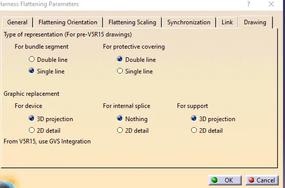
- Harness flatenning parameters are defined.

- Keep Drawing tab as shown below
- Click extract and click the face of the Back door harness connector

- It will be added as Ehf in the tree structure

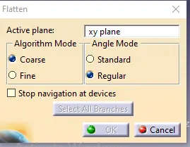
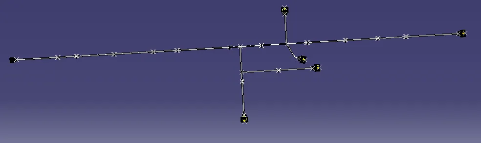
- Click flatten and click any face and click the bundles so the harness will flatten
- Use commands to arrange the bundle
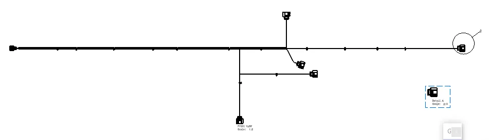
- We then open new drawing file
- Set ISO Standard and A0 as scale
- Click front view command and switch to the flatten window and click the face
- now the drawing will come to the drawing sheet.
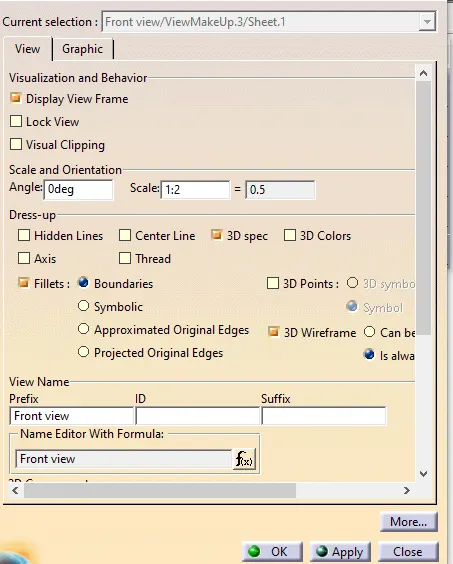
- Orient accordingly and click the properties
Rules to be followed-
- Wiring harness should be routed in such way that it is easy to assemble and access.
- Easy manufacturing, installation, removal and maintenance have to be considered while designing the wire harness.
- Wiring Harness should be kept away from sharp environment like edges, corners etc.
- Avoid harness routing and clipping in the blind zones or hard to reach areas during harness assembly or service.
- Provide additional slack if needed according to the surrounding and harness bending requirement. If harness is passing through the closures/doors or tail gates then envelope dimensions during opening and closing of doors shall be considered to provide the slack. Check the harness slack requirements with open and close conditions to avoid excess slack.
- Routing through small structural holes and openings shall be avoided. To minimize chaffing and handling of the wiring harness during installation.
- It should be make sure that there is no case of fouling while designing the wiring harness in the CAD environment. Additional mounting equipments like clips/clamps may be used to avoid fouling.
- Use of rubber grommet is recommanded if harness is passing through sheet metal panels. Example- firewall, passing to door, tail gate etc.
- The branch length should be greater than 50mm.
- The minimum distance between the clip and branch point should be at least 25mm.
- The minimum distance between the two branch points should be at least 50mm.
- Clips/clamps used for the wiring harness should be easily available in the market to avoid extra cost for custom mounting solutions So with the Above Rules we have made the back door harness.
- We have used Connectors 173090 - 2 pole connector, 1563689-1 4 Pole and 776438-4 12 poles Connectors
- 2 pole connector is used for the Locking mechanism
- 4 pole connector we have used 4 in numbers. For Light housing, Wiper motor and Back camera
- 12 Pole connector is used for interconnection
- We have used COT tubes on all required areas According to diameter
- Furr tree clips are used for clamping.